
Abstract
In large-scale and spacious environments, keeping a reliable data association and reducing computational complexity are challenges for the implementation of Simultaneous Localization and Mapping (SLAM). Focused on these problems, a multilayer-matching-based incremental SLAM algorithm is proposed in this article. In this algorithm, SLAM is simplified as a problem composed of a least-square-based optimization problem and data association. Then, it is solved in two steps. Firstly, a multilayer matching method is applied to deal with the data-association problem. Both matching between observation and local map and matching between different local maps are carried out. The uncertainty of the results-matching is described by the Fisher information matrix. Secondly, the robot pose is optimized through an incremental QR decomposition method. This algorithm effectively avoids the local minima caused by the limited observation information, and can build a consistent map of the environment. Meanwhile, the characters (hierarchical and incremental) of the proposed algorithm ensure low computational complexity. Experiments on simulation environments and two kinds of real environments with different sparse features verify that the algorithm is applicable for real-time application in large-scale and spacious environments.
Introduction
Reliable concurrent map building and localization and navigation based on the maps built are the basis for mobile robots to fulfil their assignments. Simultaneous localization and mapping (SLAM) is one of the key enabling technologies for mobile-robot navigation [1, 2, 3]. SLAM addresses the problem of acquiring a spatial map of the environment while simultaneously localizing the robot relative to this model.
After decades of development at the theoretical or conceptual level, SLAM could be regarded as a mature problem [1]. In large-scale and spacious environments, however, there are still numerous problems to be solved [2, 4] from the practical standpoint. A hybrid map is widely used to deal with large-scale environments. For example, in a recent work, SDP-SLAM [5] which combines the benefits of the SegSLAM algorithm [6] and the DP-SLAM method [7], was shown to generate more accurate maps with low alignment errors in submap combinations. Besides the accuracy problem in map-building, high computational complexity is also an important problem in large-scale environments. In order to reduce the computational effort required for solving large-scale SLAM problems, in reference [8] a decoupled SLAM (D-SLAM) algorithm for large-scale-environment map-building that combines local maps is presented; it has significant computational advantages, which are illustrated through computer simulations.
The algorithm's computational complexity can be reduced by reducing posture numbers as described in reference [9].
However, most of the existing methods mentioned above have not taken into the consideration spatial characteristics in large-scale environments. Spacious environments widely exist in urban environments (such as gardens, campuses and squares) and industry environments (such as electric transformer substations). A laser range finder (LRF) has been widely used in these situations for reasons of precision. However, due to the character of spacious environments, only a small amount environmental information is received by an LRF. This brings a great challenge to SLAM in the areas of data association and computational complexity.
Several approaches have been reported in the literature to investigate the SLAM problem in such spacious and large-scale environments. Based on sparse extended information filtering, Thrun [10] successfully solves the SLAM problem in a park environment. However, the study focuses on the localization filter of some special environmental features (trees) and cannot be applied to environments with no such obvious characteristics. Huang [11] proposes sparse local submap joining filter (SLSJF) for map-building in large-scale environments. However, this also depends on environmental features. Estrada [12] presents a hierarchical mapping method with efficient maintenance of loop consistency. Another category of SLAM approaches [13,14, 15] matches the raw LRF data with the environment map directly. These approaches do not extract environmental features, and offer universal and practical methods for general environments. As with the improvement algorithms of FastSLAM [16] and FastSLAM 2.0 [17], GMapping [18] is more effective in terms of both accuracy and time consumption of the algorithm. Data association is solved through the traversing method, which uses raw laser-range-finder data to acquire accurate grid maps instead of predefined landmarks. Map matching and data correlation are resolved with the help of a local histogram [14], which reduces the computational complexity and can be used in large-scale environments. The above methods have shown good performance in campuses, parks and urban environments. However, since they do not explicitly take characteristics of a spacious environment into consideration in the system design explicitly, they can still fall into local minima or even risk failure when the robot is placed in a spacious environment, due to the scarce observation information with large amounts of sensor noise.
Based on the analysis mentioned above, the SLAM problem is still an open issue in large-scale and spacious environments requiring higher localization precision and lower computational cost. A multilayer-matching-based Incremental SLAM algorithm (M2ISLAM) is proposed in this article. In this algorithm, the data-association problem is solved by the multilayer matching method, and the uncertainty is described with the Fisher information matrix. The key innovation of this article is that the multilayer matching method effectively avoids the local minima caused by scarce environmental information, establishes a consistent environmental map and ensures low computational complexity of the algorithm.
The proposed algorithm is tested and compared with the GMapping algorithm in two environments with different sparse features. The results demonstrate the high precision and real-time performance of the proposed method in large-scale and spacious environments.
SLAM Problem Definition and Algorithm Architecture
Preliminaries
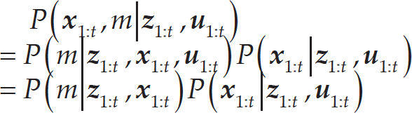
The SLAM problem, as defined in the rich body of literature on SLAM, is described as the estimation of posterior probability P(
A robot's pose at time t will be denoted as
As shown in equation (1), the map m depends on the robot trajectory and the observation of corresponding sensors. Furthermore, SLAM will be simplified to the problem of robot trajectory estimation [1]:

P{

where P(
Kinematics and observation models of robot are generally assumed such that they meet the Gaussian distribution. Then, they are converted to the following form:
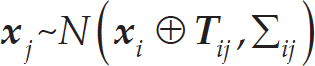
In equation (4), the operator ⊕ expresses the coordinate transformation. T
ij
and Σ
ij
represent respectively the mean and the information matrix of a constraint relating the parameters x
i
and x
j
. In the following paragraphs, as the main contribution of this article,
According to equations (3) and (4), the following is obtained:

In equation (5), ℂ is all of the possible values of i and j. Previously, SLAM has been simplified to a least-square problem based on graph optimization [19]. f
j
(

In equation (6),
After the

In equation (7),

Figure 1 shows the system structure of the proposed algorithm. The SLAM problem is simplified into two parts: data association and graph optimization. The robot pose is optimized through the incremental QR decomposition method.
As the key part of SLAM, data association determines the accuracy of SLAM. The constraint relationship

Architecture of M2ISLAM
Obviously, the matching between z
t
and z1:t−1 cannot be done by ICP due to the computational complexity. The
In the second part (graph optimization), the features of environments are not extracted, and the
Firstly, the matching between reference and observation points is considered. The collection of reference points is marked as


A searching for the closest points should be carried out several times in one iterative process; this plays a key role in the ICP algorithm's performance. The K-D tree method [26] is used in this article to collect the reference points and reduce the computational complexity. Furthermore, observations which do not match with others due to the noise and unknown obstacles will be discarded. That is to say, they will be discarded in equations (10) and (11) if
Then, the poses' constraint problem during robot navigation is analysed. z
t
is the observation at time t. There are data associations between z1:t−1 and the environmental information included in z
t
. These associations will be divided into two categories according to their continuity (continuous and discontinuous). As shown in Figure 2, the robot starts from

Example of poses' constraint
For the poses' constraint, whose observations are adjacent on time, as shown in Figure 3-a and Figure 3-b,
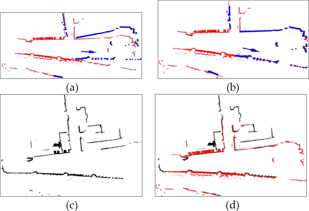
Matching process between observation and local maps. (a) Red map denotes local map
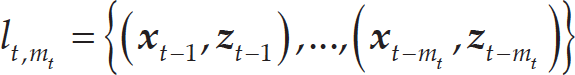
We will now analyse a situation where the robot returns to the region it has explored at time τ. In spacious environments, there are no significant differences between most observations. Eventually, the accumulated error after long-distance navigation would cause there to be a great difference between the initial value of the iterative matching algorithm and true value. It is therefore easy to fall into local minima if the matching is processed based only on single-frame observations. Therefore, in this article,
The computational complexity of the matching method is determined by the area of the local map. In this article, τ ∊ {τ j } has been discretized according to the length of navigation. The local map is built once the robot travels a fixed distance of w threshold at time τj+1.
If the intersection of boundary convex hulls between l t,m t and lτ,mτ is greater than a certain area (it also will be determined by experience during experiments), there is an overlap between l t,m t and lτ,mτ. Then, the ICP matching between l t,m t and lτ,mτ will be carried out.
Figure 3 describes the process of the multilayer-matching algorithm expressed as follows:
If the robot does not return to an area it has already explored, step 3 and one-time ICP matching will be executed; therefore, the computational complexity is a certain value, o(1). If the robot returns to an area it has explored, step 5 and matching between the current local map and all the previous local maps is carried out to obtain the explored area; then, the time consumption of ICP matching is denoted by T
icp
′. Thus, the computational complexity will be o(n) + T
icp
′. The best condition for the proposed algorithm is that the robot never returns to an area it has already explored; then, the computational complexity is o(n). The worst condition is that the robot constantly regards the current observation as belonging to areas it has previously explored; then, the computational complexity is o(n2) + T
icp
′o(n). Therefore, this algorithm could be used in real-time applications, and the reliable constraint
After multilayer matching, the uncertainty of matching results will be estimated. The accurate estimation of uncertainty can effectively improve the accuracy of the established map, and inaccurate estimation can lead to an inconsistent map and even damage to the established map.
Assuming that the uncertainty of matching results meets the Gaussian distribution with zero mean, only the covariance
The Fisher information matrix is defined as the function of expected measurement and the surface slope scanned by the laser sensor [28]. After discretization, it is used as the uncertainty estimation of matching results. The Fisher information matrix of observation z t is shown as follows [28]:

P is the pose of the robot. r
k
is the measurement of the No. k laser ray. Σ2 is the variance of noise in the laser data. s
k
is the impact factor of the No.k laser ray. λr
k
/ΔP denotes the observation change Δr
k
in the laser scan when the robot moves ΔP = [Δx
P
, Δy
P
, Δθ
P
]
T
. As the function of observation s
k
, it also can be regarded as the contribution to the localizability. The greater the deviation between r
k
and

According to the Cramér-Rao Bound (CRB) principle [29], the overall performance of the current localization is described by matrix

If the robot navigates in a 2-D environment:


Laser scan with different constraints
As shown in Figure 4, we define the observation as {r k } when the pose is P and assume the observation is {r′ g } when the pose is P′. Then, the following is obtained:

In equation (17), f(k) represents the scanning angle corresponding to observation value r k of the No.k laser ray.
Since the observation when the pose is P′ and P′ = P + ΔP is tenable, {r′ g } is obtained in equation (17). Then, Δr k /ΔP is also obtained. So, according to the analysis of equations (13) and (15), the covariance Σ can be determined by Δr k /ΔP. The estimation of matching results' uncertainty is thus completed.
Real Experiments
The real experimental environment in this article is an unmanned substation, a typical large-scale and spacious environment. Usually, the area of a 220 KV substation is around 80,000 m2. The scale of a 500 KV substation is larger. In electric transformer substations, the electric plants are usually placed sparsely due to safety issues. A part of a realistic scene and its corresponding scan map in substations for 2D-LRF are shown in Figure 5. The scan range of LRF is 18 m, the scan scale is 270°, and the resolution is 0.5°. The spacious feature of the substation environment is shown in the fact that fewer than 10 poles have been scanned by the LRF sensor and displayed in the local map.

The realistic scene and scan map of part of a substation
In recent years, some studies have executed the application of intelligent mobile robots for inspecting substation equipment [30]. The inspecting robot is used to improve the quality of detection and accelerate the process of setting up unmanned substations. It can be guided by magnetic guidance, vision navigation, or combined GPS/dead-reckoning (DR) navigation [30]. In this article, SLAM is used to deal with robots' localization and navigation problems in substations.
As shown in Figure 6, the inspection mobile robot is used to verify the proposed algorithm. The mobile robot is equipped with an odometer and LRF (SICK LMS111). Consistent with the setting in Figure 5, the same parameters are set for LRF. A laptop with an Intel Core i5 2410M CPU and a 4G DDR3 RAM is used as the control computer.
Considering the noise of the LRF sensor, set E=0.3m. A larger w threshold will increase the computational complexity of local map matching, and a smaller w threshold can cause multilayer matching failure, w threshold = 2m is used in this experiment. In the Fisher information matrix, Δx T = Δy T = 0.1m and Δθ T = 0.1 are used.

Prototype of the robot for experiments
In order to verify the validity of the proposed algorithm, the GMapping [11] algorithm is selected to compare with the proposed algorithm (M2ISLAM). GMapping does not rely on predefined landmarks and uses raw laser-range-finder data to acquire accurate grid maps; it is more robust and accurate for generating maps in different scales of environment than FastSLAM 2.0 [17]. Compared to other SLAM algorithms, GMapping shows good performance in a campus environment in Freiburg. The Freiburg campus, with an area of 250 m*250 m, is similar to a substation environment. Experiments are respectively carried out in two substations (shown in Figure 7) with different environmental features (A: 220 KV substation - electric plants are placed densely; B: 500 KV substation - electric plants are placed relatively sparsely). Because the algorithm of GMapping is non-deterministic, the maps whose results are most general and typical are selected. The localization results are determined by averaging the testing values of repeated measurements.

Planar map and raw data in substation A and B
The robot is controlled remotely at a speed of 0.4 m/s. Sensor information from the LRF and the odometer readings are gathered and recorded with a frequency of 10 Hz. After the process of remote control, the GMapping and the M2ISLAM algorithms are respectively tested with sensor information. The time-consumption of the process and the accuracy of mapping are respectively recorded to compare their validity, ε is defined as the robot pose error [31], expressed as follows:
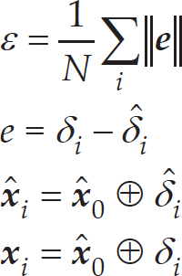
In equation (18),

It is difficult to measure and record the true value,

Measurement of the true pose of the robot
Quantitative results of different approaches/scenarios (errors with 1-Norm and 2-Norm are given). ε t (error in x and y directions), ε r (error of angle) and t (time-consumption) of the two algorithms in two substations are shown in Table 1. Through the results in Table 1, compared with the GMapping method, M2ISLAM is more accurate.
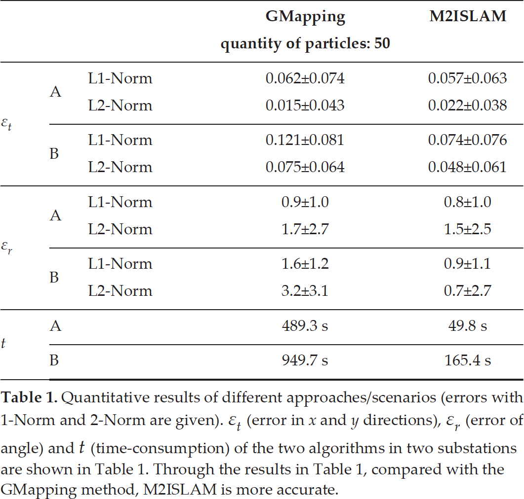
From Table 1, for both the M2ISLAM and the GMapping algorithm, time consumption of information processing is less than the time consumption of information acquisition. Therefore, both could be used in real-time applications. The time consumption of M2ISLAM is only 1/5∼1/9 of that of GMapping. This is because only the optimal trajectory of the robot should be maintained and optimized according to the matching results in the M2LSLAM algorithm, but multiple trajectory assumptions should be maintained in the GMapping algorithm (each particle represents a hypothesis).
We will now analyse the mapping performance of GMapping and M2ISLAM in detail.
In a 220 KV transformer substation, electric plants are placed densely with no loop closure. The length of trajectory in substation A is 399.8 m. Data on a total of 6858 frames are gathered, and the process costs 690 s. The maps built by the M2ISLAM and GMapping algorithms are shown in Figure 9.

Raw data and the maps of substation A
As shown in Figure 9, compared to the planar map of substation A (shown in Figure 7) the angle error of the map built by the M2ISLAM algorithm is 3.3°. However, the angle error of the map built by the GMapping algorithm is 7.0°. In addition, compared with GMapping, the pose error ε t and angle error ε r of M2ISLAM decrease by about 10% (1-Norm index). For the experiment in substation A, when the robot explores the environment it never returns to an area it has explored: there is no loop closure in substation A, unlike in substation B. In substation A, the proposed algorithm was therefore not effective. The performance of M2ISLAM is worse than GMapping in L2-Norm. In substation B, where there is large loop closure, the robot can observe the repeated information. For the multilayer matching method used in the paper, the matching between different local maps will correct the pose of the robot and obtain more accurate maps, both in L1-Norm and L2-Norm. Therefore, the conclusion is that the M2ISLAM algorithm is able to effectively improve the accuracy of mapping and localization and overcome the match failure problem caused by scarce sensor information in such spacious environments.
In order to verify the proposed algorithm's effectiveness in loop closure, the experiments in substation B are analysed in this section. Compared with substation A, substation B had the following properties:
The area is larger, and the trajectory is more than 1300 m. There are more loop closures; the robot can arrive at the same destination by different paths.
The electric plants are placed more spaciously. Less information is gathered by the robot. As shown in Figure 7, information on only five poles is detected, and more than 90% of the laser rays reached maximum measurement range.
There is more sensor information noise. On the one hand, the ground is not flat, so the assumption of a 2D plane cannot stand. On the other hand, there are more obstructions, such as bushes, which are difficult to measure with LRF.
Data on a total of 117, 228 frames are gathered during remote control, and the process cost 1180 s. As shown in Figure 7, the robot explores

Raw data and the maps of substation B
The robot enters
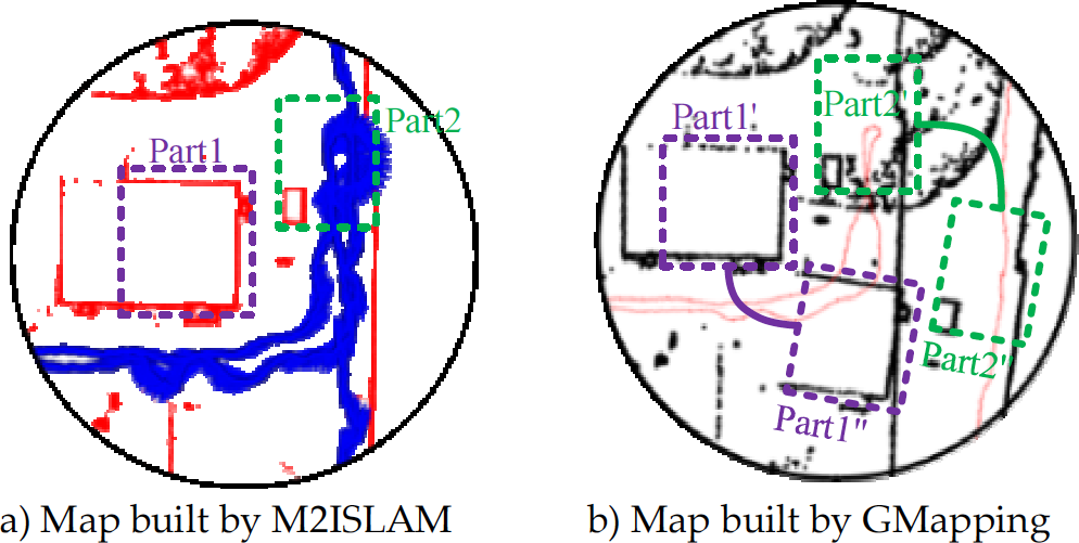
The maps of area3
In order to verify the performance of the proposed algorithm, an open-source simulation platform [32] is used, which is implemented in Gazebo and ROS. Integrated with kinematics, dynamics, and laser sensor, the robot in the simulation platform can also be controlled manually through a joystick for driver training (manual mode). In this simulation platform [32], the model of LRF (SICK LMS111) is embedded, the flicker noise and white noise [33] are fused in the laser-scan observation, and the error model of the odometer is also built. The ground truth of the robot pose could be outputted directly to be compared with the experimental result.

Simulation Platform
This platform runs on a laptop with i3 1.9GHz CPU and 4G RAM. A parking scenario (50 m*70 m), illustrated in Figure 12, is built using SketchUp. There are some cars, trees and bushes. The process is the same as in the real experiments. Figure 13 shows the maps built by the M2ISLAM and GMapping algorithms; the map of area4 built by GMapping observably fails.
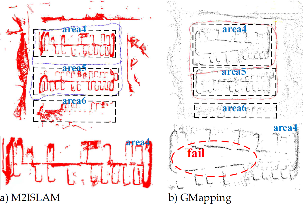
The maps of the simulation scenario
After mapping, the robot navigates to 10 test points (shown in Figure 12) in manual mode in the M2ISLAM and GMapping maps (with 50 and 100 particles). The ground truth and estimated value of the robot pose are recorded. Then, e t (error in x and y directions) and e r (error of angle) of the two algorithms are also obtained, as shown in Table 2.
Quantitative results in simulation scenario

From Table 2, the localization accuracy of M2ISLAM is near to that of GMapping with 100 particles, and is more accurate than that of GMapping with 50 particles. The results of the simulation experiments are similar to those of the real experiments.
The source code of the proposed algorithm is available under the following link: http://robocup.situ.edu.cn/athome/msslam.htm
The SLAM algorithm is analysed in large-scale and spacious environments in this article, and a multilayer matching-based incremental SLAM algorithm is proposed. The SLAM problem is simplified into two parts: data association and least-squares optimization. For the data-association problem for SLAM in large-scale and spacious environments, the multilayer matching method is presented, and the Fisher information matrix is used to analyse the uncertainty of matching results. The local minima caused by the scarce information are avoided effectively, and accumulation of incorrect matching is reduced. The incremental QR decomposition is also used to improve the real-time ability and efficiency of the algorithm. The algorithm is tested on a simulation platform and also successfully applied to the inspection robot in transformer substations. As typical large-scale and spacious environments, two substations with different characteristics are selected to verify the proposed algorithm and compare its performance with common SLAM methods. The results show that the proposed algorithm could be applied in actual industrial environments.
Footnotes
7.
This work is partly supported by the National High Technology Research and Development Program of China under grant 2012AA041403 and the Natural Science Foundation of China under grant 61175088.