
Abstract
A new control method for an electromagnetic unmanned robot applied to automotive testing (URAT) and based on improved Smith predictor compensator, and considering a time delay, is proposed. The mechanical system structure and the control system structure are presented. The electromagnetic URAT adopts pulse width modulation (PWM) control, while the displacement and the current doubles as a closed-loop control strategy. The coordinated control method of multiple manipulators for the electromagnetic URAT, e.g., a skilled human driver with intelligent decision-making ability is provided, and the improved Smith predictor compensator controller for the electromagnetic URAT considering a time delay is designed. Experiments are conducted using a Ford FOCUS automobile. Comparisons between the PID control method and the proposed method are conducted. Experimental results show that the proposed method can achieve the accurate tracking of the target vehicle's speed and reduce the mileage derivation of autonomous driving, which meets the requirements of national test standards.
Introduction
The improvement of automotive design and manufacturing requires a large number of automotive tests. These tests include emission durability tests, fuel economy tests, transmission losses and power transfer performance tests, high temperature and cold temperature environmental tests, automotive noise tests, etc. It takes a long time for automotive tests to be completed. For example, it takes more than half a year to conduct emission durability tests for a human driver. In the automotive sector, accurate and repeatable procedures are desirable for automotive tests. In many automotive tests, e.g., the emission durability test and fuel economy test, the driver's driving behaviour is one of the sources for statistical and system errors [1–3]. URAT is a kind of industrial robot that can achieve autonomous driving under dangerous conditions and harsh environments. Instead of employing a human driver, it can be installed in the automobile cab without the need for any modification of the automobile and can be adapted to different automobile models [4]. URAT is also called a robot driver or robotic driver. URAT has advantages in terms of test time, cost and test accuracy. It can free human drivers from uncomfortable and tedious working conditions, improve the objectivity and accuracy of test results, provide more reliable and repeatable test results than human drivers can, and markedly shorten the development procedures of new automobile models [5, 6].
The drive style of URAT consists of a hydraulic drive, pneumatic drive and electric drive. Enfu Chen developed The drive style of URAT consists of a hydraulic drive, the hydraulic shift mechanical arm. The hydraulic drive is pneumatic drive and electric drive. Enfu Chen developed stable, but hydraulic oil is provided by a hydraulic pump the hydraulic shift mechanical arm. The hydraulic drive is system, creating a higher risk of more failure points and stable, but hydraulic oil is provided by a hydraulic pump making the shift manipulator system structure more system, creating a higher risk of more failure points and complex [7]. Weigong Zhang designed a seven link two-DOF (Degree Of Freedom) closed chain shift mechanical arm and designed a pneumatic drive shift mechanical arm and servo motor, as well as a ball screw shift mechanical arm [8]. However, it is difficult for a pneumatic drive to achieve trajectory control and multi-point accurate positioning. Nicholas Wong designed a simple shift mechanical arm, where a stepper motor drives the movement of gears [9]. However, the electric drive has limits in terms of control principles, so that the control accuracy of positioning and force is low, and speed control is unsteady. An EMLM (electromagnetic linear motor) can convert electrical energy into mechanical energy in the form of linear motion. This process requires no conversion device. Its characteristics are high efficiency, small size, light weight, high precision and fast dynamic response [10–14].
URAT must realize the accurate tracking of target vehicle speed and reduce the mileage derivation of autonomous driving for a vehicle's test driving cycle. Some speed control methods exist for robotic drivers. Chen Xiaobing et al. utilized variable parameter PID control to realize speed tracking for URAT. However, it had the disadvantage that the control parameters had difficulty tuning speed fluctuations were considerable [5]. Chambers et al. [15] established a PID controller, but one that showed poor accuracy. Furthermore, adaptation to different types of automobile must be done intuitively and stability cannot be ensured. Gang Chen et al. [1, 2] presented a speed tracking control method using multiple sliding surface control schemes and a fuzzy neural network; however, the method cannot meet the cumulative error requirements of driving mileage derivation. Therefore, in this paper, we propose an improved Smith compensator predictor to be used in parallel with the control object [16, 17].
In view of the above, a new control method for electromagnetic URAT using the improved Smith predictor compensator and considering time delay is proposed. The mechanical system structure and control system structure are presented. The coordinated control method of multiple manipulators for the electromagnetic URAT, e.g., a skilled human driver with intelligent decision-making ability is provided. Furthermore, the improved Smith predictor compensator controller for the electromagnetic URAT considering time delay is designed. Experiments are performed using a Ford FOCUS automobile. Experimental results demonstrate the effectiveness of the proposed control method.
Mechanical System Structure
Electromagnetic URAT primarily consists of a throttle mechanical leg, brake mechanical leg, clutch mechanical leg, shift mechanical arm and their drive unit, EMLM. Electromagnetic URAT can directly drive the throttle mechanical leg, brake mechanical leg, clutch mechanical leg and shift mechanical arm through EMLM. It does not need intermediate transmission links. The operation of the electromagnetic URAT is flexible and rapid like a human driver, which meets the movement requirements for the rapidity of shifting and braking, slow movement for throttle and rapidity combined with slow movement for clutch. Figure 1(a) shows the system configuration of electromagnetic URAT. Electromagnetic URAT does not only meet the requirements of high stability and real time for the URAT control system, but also improves the control accuracy and repeatability of automotive test.

Electromagnetic URAT
The shift manipulator adopts a seven-link two-DOF closed-chain mechanism, the internal structure of which is shown in Figure 1(b). With no need to change the automobile shift mechanism, mechanical decoupling between both selecting a gear and engaging a gear is achieved and precise control for the shift manipulator of URAT is achieved. To achieve the decoupling between selecting a gear motion control and engaging a gear motion control, at the time of picking a gear and engaging a gear, only the engaging gear motor is manipulated and the selecting gear motor remains stationary. Conversely, at the time of selecting a gear, only the selecting gear motor is manipulated and the engaging gear motor remains stationary.
Control System Structure
The measurement and control system for electromagnetic URAT achieves the acquisition and processing of the signals, and the control of mechanical actuators. The control system structure for electromagnetic URAT is shown in Figure 2.

Control system structure of electromagnetic URAT
The TMS320F2812 DSP chip is the core of electromagnetic URAT control system. The current position of the mechanical actuators, the displacement and current of EMLM, vehicle speed and engine speed are transferred to DSP. Then, according to the input data, the test cycle condition is pre-entered into computer memory and the actuator command signals are calculated in real time.
The vehicle speed is measured via a photoelectric sensor installed in the front drum of the chassis dynamometer. The displacement of the throttle, brake and clutch is measured by potentiometer displacement sensors, which is installed in the throttle mechanical leg, brake mechanical leg and clutch mechanical leg, respectively. After the sensors' output signals are calibrated, the corresponding displacement of throttle, brake and clutch are obtained. Meanwhile, the gear is measured by a potentiometer angle sensor installed in the shift mechanical arm.
The motion control system of the electromagnetic URAT consists of a DA962D serial drive board and a H-bridge.
The H-bridge is composed of four MOSFET tubes. The servo control unit receives signals from the DSP chip. The EMLM control adopts the PWM. The EMLM control algorithm adopts the double closed loop control strategy of displacement and current.
By means of changing the polarity and duty cycle of the PWM signal, the DSP controller changes the direction and magnitude of the EMLM current. Then, the control signals are amplified by the drive module. The precise control of electromagnetic URAT is achieved by the saturation current.
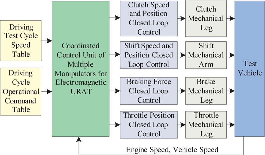
The multiple manipulators coordinate the force, speed, displacement and timing, so that the electromagnetic URAT control system completes the motion control of the robot itself and realize the tracking of the vehicle speed. The best control approach for URAT is to employ a human driver approach, which has the coordination relation of time, displacement, force and speed. A good coordinated control method of URAT should be like that of a skilled human driver. URAT has sensor information perception, intelligent decision-making and actuator control. It has intelligent decision-making abilities and can achieve the coordinated control of a throttle mechanical leg, clutch mechanical leg, brake mechanical leg and shift mechanical arm for electromagnetic URAT. The relationship between the coordinated control model, vehicles and the robot is shown in Figure 3.

Relationship between the coordinated control model, vehicles and URAT
A series of information consisting of speed v
The coordinated control model block diagram
According to operational requirements, each manipulator motion closed-loop, respectively, constitutes braking force control closed-loop, clutch speed and position control closed-loop, throttle position control closed-loop and shift speed and position control closed-loop. The manipulator motion closed-loops can achieve the precise positioning of throttle, the precise control of brake deceleration through self-adjusting braking force and the adjustment of clutch engage speed. The movement of the shift mechanical arm is fed back by the angular displacement sensors of both selecting a gear joint and engaging a gear joint. Spatial displacement is determined by angular displacement. Without the need to modify the shift mechanism, mechanical decoupling between both selecting a gear and engaging a gear is achieved. In accordance with the set vehicle speed and control command tables, electromagnetic URAT achieves the coordinated control of the multiple manipulators and realizes the tracking of vehicle speed. The speed and driving commands table of a 48 km/h driving cycle for electromagnetic URAT is shown in Table 1.
Speed and driving commands table for a 48 km/h driving cycle for electromagnetic URAT

The controller structure of electromagnetic URAT is shown in Figure 5. It consists of two cascaded controllers, namely the position controller and the speed controller. According to the error of target speed and actual speed, the speed controller sends position commands to the position sensor. The position command represents the desired pedal position. The position controller controls the mechanical actuators such as throttle mechanical leg and brake mechanical leg. Based on the desired position gained from the speed sensor and the position feedback from the encoder, by changing the polarity and duty cycle of the PWM signal, the position controller changes the current of EMLM. When the target speed is consistent with the actual speed, the speed error is zero, so that it achieves smooth control.

The controller structure
The actions of multiple manipulators not only have strict action timing, but are also coordinated with the parallel execution process. The multiple manipulators need to coordinate the force, speed, displacement and timing in order to complete the motion control of the robotic mechanical structure itself and realize the tracking of the vehicle's speed. Since the dynamic characteristics and movements of the mechanical actuators differ from one another, they require different control algorithms in order to meet the control needs. The clutch mechanical leg adopts full amount PID control. The throttle mechanical leg adopts incremental PID control. The brake mechanical leg adopts force closed loop control. The shift mechanical arm adopts force and position hybrid control.
In the process of driving, after the robot mechanical legs pedal push down, there is a period of delay for the vehicle before speed is stabilized. Thus, the automotive throttle/brake and the speed control system is a delay system. Therefore, in the control process, the measured speed is not the corresponding position, so that there will be a range of difficulties requiring control. Thus, considering an automobile as the delay system, we add to it a compensator in the control loop. The control loop is shown in Figure 6.

The control loop considering delay
Where vd is the target speed, vm is the actual speed, e(s)=vd(s)-vm(s), vr is the movement speed of the robot mechanical leg, Gc (s) is the regulator transfer function and

If the delay coefficient τ is too large, the control will be unstable. Therefore, we propose an improved compensator, the Smith predictor, in parallel with the control object. Assuming that the transfer function is Gτ (s), the control loop is shown in Figure 7.

The control loop with parallel compensator
Thus,
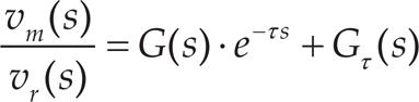
To compensate the delay e −τs, assume,
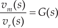
Thus,

Therefore,
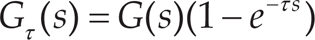
Taking equation (5) as the Smith predictor, the modified control loop is shown in Figure 8.

The modified control loop with improved Smith predictor compensator
Experimental Design
To verify the effectiveness of the proposed method for electromagnetic UKAT, according to the national pollution emissions standards for passenger cars issued by the Environmental Protection Administration of China [18], a vehicle emission durability test is performed in the Nation Quality Supervision and Inspection Center for passenger cars of China by electromagnetic URAT. The vehicle model is a Ford Focus 2.0, whose engine volume is 2.0 L. The type of chassis dynamometer is Burke 4100.
The vehicle emissions durability test system consists of a chassis dynamometer simulating driving road conditions and electromagnetic URAT conducting automatic driving instead of a human driver. The chassis dynamometer is equipped with power absorption and an inertia flywheel, which simulates road resistances including air resistance, rolling resistance and acceleration resistance, thus rendering the test environment consistent with the road environment for automobiles. Electromagnetic URAT can automatically drive and no modifications are needed for the presence of an automobile instead of a human driver. URAT manipulates the automobile according to the requirements of a pre-set driving cycle, namely time-speed curves. It can achieve the coordinated control of the throttle mechanical leg, clutch mechanical leg, brake mechanical leg and shift mechanical arm.
Following a vehicle performance self-learning method [19], including automobile dynamic parameters and vehicle characteristics change (such as components' wear), it can automatically manipulate different types of vehicles. The dynamics and structure of each vehicle are different from one another and the electromagnetic URAT needs to adapt to these changes. The vehicle structure parameters are learned by a key box. According to the instructions of the human driver, the movements of the throttle mechanical leg, the brake mechanical leg, the clutch mechanical leg and the shift mechanical arm are automatically controlled by a teaching and control program. The starting position, the ending position and the stroke of the manipulators are obtained, and in the process, the position control parameters of the manipulators are automatically adjusted. During the combination process of the clutch, the engine speed will decrease; as a result, the position of the clutch mechanical leg when the engine speed begins to decrease is a sign of the beginning of clutch engagement. The ending point of clutch engagement is obtained by the relationship between engine speed and vehicle speed. The command signals applied to the throttle and brake actuators are determined by the power needed to drive the vehicle during the process of self-learning vehicle performance parameters. The output characteristics of the engine are obtained by an engine MAP diagram. The braking performance is determined by the difference between the required vehicle drive power and the chassis dynamometer absorbed power, and the gradient descent method is used in the learning process. Furthermore, during the period of the automotive test, wear of the vehicle component parts can lead to the changes in vehicle characteristics. The control parameters self-optimization, using a least-squares algorithm, makes it possible to compensate for wearing caused to the vehicle during a long term test.
During the process of the automotive test, the driving speed and driving instructions commands of the test cycle are firstly defined; then, the automotive test is conducted by URAT. Electromagnetic URAT fixed on a test vehicle, as well as a vehicle durability test is shown in Figure 9.
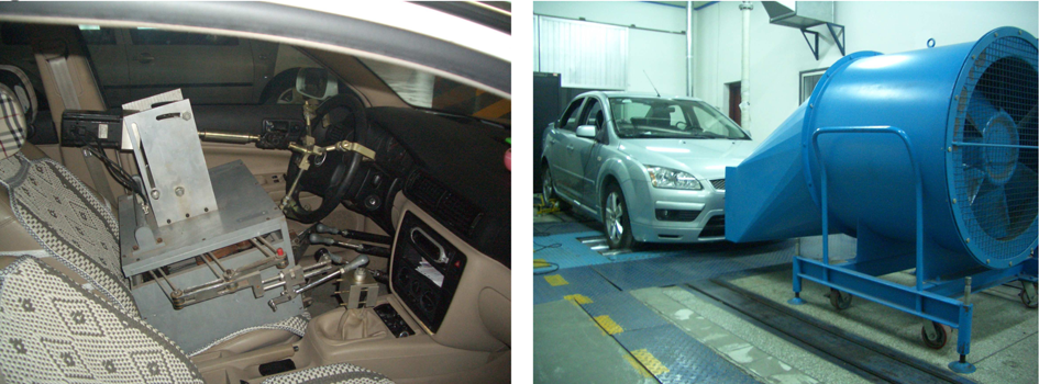
Electromagnetic URAT and emission durability test
The comparison of speed tracking results and the comparison of speed tracking error for electromagnetic URAT are shown in Figure 10 and Figure 11, respectively. The corresponding control curve of the shift mechanical arm, throttle mechanical leg, brake mechanical leg and clutch mechanical leg are shown in Figure 12 and Figure 13, respectively. As can be seen from Figure 10 and Figure 13, speed fluctuations using the PID control method are significant. The range of speed tracking error is ±6 km/h, which exceeds the requirements of the national vehicle test standard. The speed fluctuations using the proposed method, however, are significantly lower. The proposed method can realize accurate tracking of the target speed and can greatly improve the tracking accuracy of vehicle speed. The overshoot of speed tracking control during transition from acceleration to steady speed and from steady speed to deceleration is small. The speed control accuracy using the proposed method stays within a tolerance band of ±2 km/h, which meets the requirements of national test standards. Electromagnetic URAT using the proposed method smoothly achieves starting, acceleration, shifting, steady speed and deceleration through the coordinated control of the throttle mechanical leg, brake mechanical leg, clutch mechanical leg and shift mechanical arm.

Comparison of speed tracking

Error comparison of speed tracking

Control curve of the shift mechanical arm

The control curve of throttle mechanical leg, brake mechanical leg and clutch mechanical leg
The comparison of mileage deviation of electromagnetic URAT is shown in Table 2, where in each speed-mileage constraint point, the maximum mileage deviation of the proposed method and PID control method is 0.006km and 0.18km, respectively. The reason for this is because the mileage deviation of the proposed method for electromagnetic URAT is compensated during the process of movement. The speed tracking accuracy of PID control is low and the mileage deviation of PID control is accumulated.
Comparison of mileage deviations

A novel control method for electromagnetic URAT based on an improved Smith predictor compensator considering time delay is proposed. The mechanical system structure and the control system structure are presented. The electromagnetic URAT adopts PWM control and the displacement and current double closed loop control strategy. The coordinated control method of multiple manipulators for electromagnetic URAT, similar to a skilled human driver with intelligent decision-making ability, is given and the improved Smith predictor compensator controller for electromagnetic URAT considering time delay is designed. Moreover, theoretical analysis and experimental validation are made.
Experiments are performed using a Ford Focus automobile. Experimental results show that compared to the PID control method, the proposed method can achieve accurate tracking of the target vehicle speed and reduce the mileage derivation of autonomous driving. Electromagnetic URAT using the proposed control method can smoothly achieve starting, acceleration, shifting, steady speed and deceleration. The overshoot of speed tracking control during transition from the acceleration stage to steady stage is small. Moreover, the speed fluctuations at the steady stage are smooth and speed control accuracy stays within a tolerance band of ±2 km/h. In each speed-mileage constraint point, the maximum mileage deviation of electromagnetic URAT is 0.006km. The mileage deviation of electromagnetic URAT is compensated for and it meets the requirements of national test standards. Instead of a human driver, electromagnetic URAT can complete a variety of vehicle tests with high repeatability and over an extended period of time. It can automatically manipulate different models of automobiles without requiring modification.
Future Work
Future research will focus on the different driving styles of a human driver that may have an influence on the test results of URAT. Additionally, autonomous vehicles require modifications to automobile structure, while the robotic system can only drive a fixed vehicle model. Future research will focus on the vehicle robot driver applied to an autonomous vehicle.
Footnotes
7.
This research is supported by Project 51205208 supported by the National Natural Science Foundation of China.