
Abstract
An important challenge in computer vision is the implementation of fast and accurate feature detectors, as they are the basis for high-level image processing analysis and understanding. However, image feature detectors cannot be easily applied in embedded scenarios, mainly due to the fact that they are time consuming and require a significant amount of processing power. Although some feature detectors have been implemented in hardware, most implementations target a single detector under very specific constraints. This paper proposes a flexible hardware implementation approach for computing interest point extraction from grey-level images based on two different detectors, Harris and SUSAN, suitable for robotic applications. The design is based on parallel and configurable processing elements for window operators and a buffering strategy to support a coarse-grain pipeline scheme for operator sequencing. When targeted to a Virtex-6 FPGA, a throughput of 49.45 Mpixel/s (processing rate of 161 frames per second of VGA image resolution) is achieved at a clock frequency of 50 MHz.
Introduction
Many computer vision tasks rely on the extraction of low-level image features or interest points, which usually represent a small fraction of the total number of pixels in the image. Interest points are salient image pixels that are unique and distinctive, i.e., quantitatively and qualitatively different from other pixels in the image [1]. Such points must be robustly detected, meaning that they retain similar characteristics even after image geometrical transformations or illumination changes. Image features are used in several applications, ranging from object recognition [2], texture classification [3], and image mosaicing [4]. Moreover, image feature detectors and descriptors are the basis for other applications such as image retrieval in large databases, to assist visual searching and image watermarking and steganography [5]. The overall performance of those applications relies on robust and efficient image feature detection.
A wide variety of feature detectors exist, and their output varies considerably as such algorithms make different assumptions about image content in order to compute their response. Thereby, a recent trend is being made to combine the power of different detectors into a single framework to achieve better results, as information from a detector can be complemented with the corresponding information of its counterparts [6]. Despite their inherent differences, most interest point detectors are computationally similar as window-based image processing operators are required to be applied locally on every image position or scale. This makes the extraction process computationally intensive in applications for real-time embedded scenarios, such as robot navigation, self-localization, and object recognition.
Motivated for the increasing demand for high-performance, specific hardware architectures have been proposed as feature detector accelerators thanks to its inherent parallelism. Yet size, weight, and power constraints in embedded computing severely limit the implementation choices [7,8]. In this sense, field programmable gates arrays (FPGAs) appear to fit computer vision particularly well thanks to their regular parallel computational structure and the availability of on-chip distributed memory. Furthermore, FPGA technology is always improving in logic density and speed, which constantly increases the complexity of the models that can be implemented on them by software-like techniques, thus facilitating fast prototyping. While alternative parallel implementation media such as graphics processing units (GPUs) have been used to speed up computations by using threads at programming levels [9, 10], major motivating factors for choosing FPGAs are power efficiency for embedded applications, and the possibility of exporting an FPGA design to an application-specific integrated circuit (ASIC) implementation.
The main contribution of this work is the proposal of a design strategy for the FPGA-based implementation of feature detectors in a flexible hardware architecture, which relies on two main observations common to most feature detectors: window-based image processing operators and buffering schemes for operator sequencing. The architecture partially copes with the inability of previous designs to adaptively change the chip's functionality so as to address different application's requirements or environmental conditions. A detailed analysis of two case studies, the Harris and SUSAN feature detectors, are presented to validate the functionality, flexibility and real-time performance of the proposed architecture. The architecture can be used for other detectors such as the Canny edge detector and the FAST detector [11].
The rest of the paper is organized as follows. Section 2 presents some relevant work related to this research. The basics of image interest point detectors are presented in Section 3 and the specific algorithms also employed. In Section 4 an abstraction of the addressed feature detectors is presented, and the implementation strategies are outlined. Section 5 presents the hardware architecture and the tradeoffs in the design and implementation for the target algorithms. In Section 6 the experimental results are presented and the performance of the hardware implementation is discussed. The conclusions drawn and future work are presented in Section 7.
Related Work
Despite there having been considerable work on hardware implementations for feature detection, to the best of our knowledge there has not been an important research effort to provide a unified view of such algorithms so as to define a flexible hardware architecture capable of implementing more than a single detector. In this sense, Possa in [12] states that most of the previously cited works are basically a cascaded set of neighbourhood operators that must be redesigned and resynthesized for every different algorithm or frame resolution. However, it is important to point out that some efforts for methodologies and flexible hardware architectures for real-time embedded image processing have been made. For instance, Bailey in [13] provides a comprehensive overview of algorithms and techniques for implementing low and intermediate-level image processing algorithms on FPGAs. The limitations of conventional sequential processors are exposed, and different design approaches to efficiently map image processing algorithms onto FPGA-based architectures are presented. Ahlberg in [14] presents GIMME (General Image Multiview Manipulation Engine), a highly flexible FPGA-based reconfigurable standalone mobile two-camera vision platform with stereo vision capability to perform application-specific low to medium-level image-processing at video-rate. Gribbon [15] proposes the application of design patterns to reformulate an algorithm and map it to consider hardware constraints imposed on the system such as timing (limited processing time), bandwidth (limited access to data), and resource (limited system resources) constraints. For validation purposes, the authors implement a VHDL model of the Harris detector achieving a throughput of 44.4 frames per second. Tiemerding in [16] describes the hardware implementation of several image processing algorithms and compares them regarding performance, resource consumption and development time using VHDL and SystemC. In that study, three image processing algorithms (demosaicing, binary morphology, and Canny detector) are modelled and implemented within a Xilinx FPGA. It is shown that the abstraction level that encapsulates hardware-specific constructs in the design specification has an important influence on the development time and parallelism extracted. Meanwhile, the SystemC approach holds a shorter development cycle and higher flexibility than VHDL modelling, and handmade VHDL designs outperform to SystemC designs in terms of throughput and resource consumption
Recent works have presented feature detector implementations in order to meet real-time requirements in FPGA devices with a fixed or slightly configurable architecture. For instance, an FPGA-based implementation of the Harris detector within an on-board vision sensor system for small unmanned vehicle applications is presented in [8]. The corner detector is computed in two steps. First, the input image is processed using the Rank transform, and it is later thresholded to retain the features to be detected in the second step. Row buffers and shift registers are used for the transform, which is fixed to neighbourhoods of size 9×9. The actual detection is carried out in the second step and modifications to the Harris corner equations were carried out. The partial derivatives were computed using a 3×3 pixel matrix, and three rows of partial results are buffered in preparation for the corner value computation. The bit-width was manipulated in order to fit the Harris response to 26 bits.
Two optimized FPGA-based architectures for real-time image and video processing targeting Canny and Harris detectors are presented in [12]. Both architectures use a mechanism for neighbourhood extraction based on line buffers that supply neighbourhoods of variable size on different image resolutions, which is at the core of both detectors. Zero-padding for the input image was employed so as to deal with the boundary problem. In the Harris architecture the partial derivatives and Gaussian filtering are computed using neighbourhoods of 3×3 and 5×5, respectively. The Harris output values were truncated to 8 bits to preserve an 8 bit-width datapath, but an additional Gaussian filtering step using neighbourhoods of size 5×5 is needed to compensate for the saturated values and to enhance localization. Then, non-maxima suppression is applied on neighbourhoods of size 9×9. The architecture is implemented on an FPGA clocked at a frequency of 242 MHz to process a 512×512 image in 1.1 ms.
The described research on Harris implementation sacrifices accuracy by altering the original detector algorithm so as to ease the hardware implementation. This approach may be acceptable for some applications, but it is neither suitable as a general purpose standalone module, nor acceptable for many other vision applications [17]. Thus, a real-time embedded design as a standalone multi-detector module that can be easily adapted to diverse computer vision applications is highly desirable. In this endeavour, this paper presents a hardware architecture to implement two different feature detectors in a fully parallel approach on an FPGA device, taking advantage of some well known and used state-of-the-art implementation techniques. The proposed architecture can be applied to other related image processing algorithms such as edge detectors and morphological operators. When compared with some existing solutions, the proposed implementation approach has three significant advantages:
To the best of our knowledge, it is the only FPGA-based architecture that implements two different feature detectors by abstracting the fundamental components of window-based image processing while still supporting a high frame per second rate and low resource utilization in a single datapath. It provides a unified representation for feature detection and localization on an FPGA without altering in any way the nature of the algorithms, keeping a reliable hardware response that is not compromised by simplifications beyond the use of fixed-point arithmetic. The architectural components were designed to allow flexible processing and scalability, which can potentially be used to accommodate other feature detectors or similar window-based image processing algorithms.
Interest Point Detectors
Interest points are simple point features, image pixels that are salient or unique when compared with neighbouring pixels. Most interest point detectors include two stages: i) detection that involves a measure of how salient each pixel is, and ii) localization that selects stable points determined by local non-maxima suppression. Both criteria are application dependent.
An interest point operator can be obtained using a mapping of the form κ:ℝ+ → ℝ so as to measure how salient or interesting each pixel is [18]. Interest point detectors differ on the operator κ that they employ. Usually, a detector refers to the complete algorithmic process that extracts interest points from an input image I to produce and interest image I*, and the κ operator only computes the interest measure for a given pixel based on local information.
Interest point localization performs non-maxima suppression to eliminate highlighted pixels that are not local maxima, and then usually a thresholding step is applied. Interest points that are greater than a specified threshold are identified as local maxima of the interest point measure response according to equation:
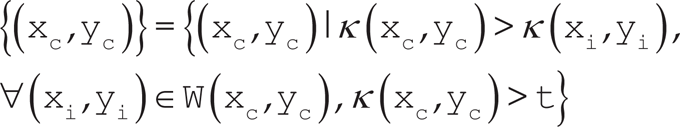
where (xc,yc) is the set of all interest points, κ(x,y)is the interest point measure response computed at point (x,y), W(xc,yc)is a neighbourhood centred around the point (xc,yc), and t is a specified threshold.
Given the vast diversity of feature detectors reported in the literature, a quantitative performance evaluation is an important procedure to assess the quality of feature detectors [1,19,20]. Based on such studies, in this work two well-known non-multiscale corner detectors, Harris and SUSAN, are used as case studies based on the assessed performance in terms of localization and stability properties when they are applied to real data. For multiscale feature detection algorithms such as SIFT, a different approach based on kernel decomposition, is preferable to that proposed in the present work.
This edge and corner detector algorithm was proposed by [21], and it relies on the following principle: the image intensity changes significantly in multiple directions at a corner, while the image intensity changes greatly only in a certain direction at an edge. The first order partial derivatives of the image are calculated and then smoothed with a Gaussian kernel Gσ. For each pixel in the image at position (x,y) the Harris matrix is then computed:

where a, b and c are the scalar values that result from convolving a Gaussian kernel against the first order partial derivatives of an image I over x and y directions, that is,

The main changes in both directions in an image intensity pattern are related to the eigenvalues of the Harris matrix for that image. Thus, large eigenvalues correspond to locations with relevant signal changes. A single expression that puts together the two eigenvalues for computing the measure of a point is given by:

and k is a constant with a typical value of 0.04. The Harris measure is then used to decide if a corner (
In this detector the measure κ is based on the comparison of the intensity of pixels within local circular regions in an image and the intensity of the centre pixel of such regions [22]. The centre pixel is referred to as the nucleus. Pixels within the circular regions are compared against the corresponding nucleus, and the resulting value is thresholded to decide if the intensity is similar, or not, to that of the nucleus, that is:

where the intensity values of the nucleus and the pixels within the circular regions are
Each pixel in the image is associated with a local area corresponding to a portion of the circular region with similar intensity. Such a portion is called USAN (univalue segment assimilating nucleus), and depending upon its area, an edge, corner or flat region is determined. The computation of the USAN area n is straightforward, and is given by:

The response of the detector is computed by comparing n to the geometric threshold g=3/4nmax, where nmax is the total count of pixels within the circular region. A typical value for nmax in a 7×7 neighbourhood is 37 pixels. The response κ is given by:

Harris and SUSAN feature detectors rely on the notion of window-based image processing for computing their response. In the following section this topic is covered, laying out the basis for constructing the target architecture.
Window-based Processing
A window-based operation is performed when a window of k × k pixels is extracted from the input image and is transformed according to a window mask or kernel and mathematical functions to produce an output result [23]. Usually single output data are produced by each window operation and stored in the same position as the central pixel of the window, as shown in Figure 1(a).
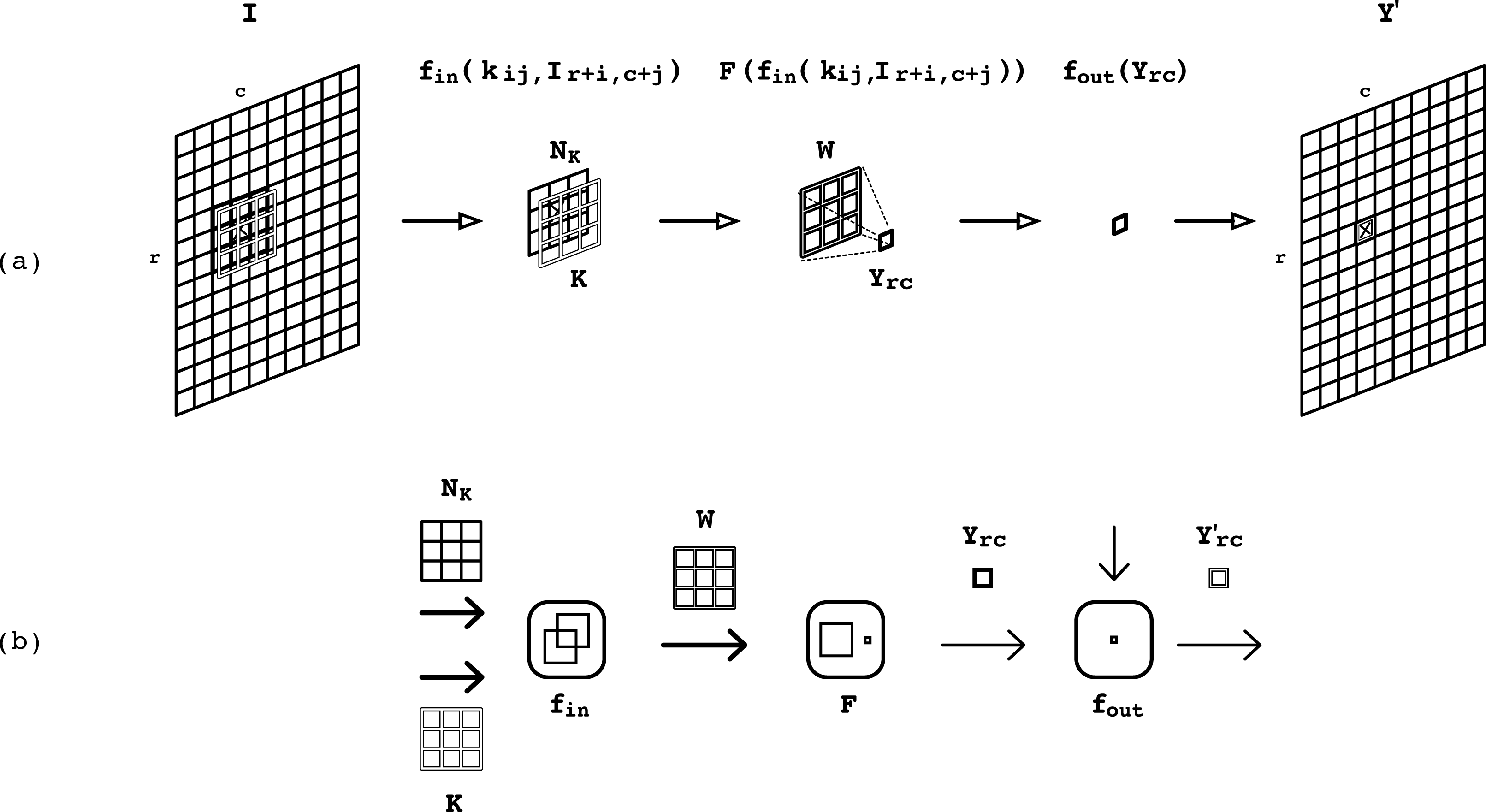
An input image I is processed using a kernel K that is overlapped on every extracted neighbourhood centred at location (r,c) in the input image. The crosses mark the location (r,c). An output window W is computed from operating the extracted neighbourhood against the kernel. This window is then reduced to a single output pixel, which is operated and placed at location (r,c) in the output image Y'.
Window-based operations can be formalized as follows. Let I be the M×N input image, Ythe output image, and K a k × k kernel. A window operation can be defined as:

where kij represents a coefficient from the kernel K, Ir+i,c+j, represents a pixel from a k × k neighbourhood NK around the (r,c) pixel in the input image, fin defines a scalar function, and F defines the local reduction function. Normally the output value is combined with other scalars, or compared to a threshold value by means of a scalar function fout to produce a final response Y'rc:

Common scalar functions, usually two input operands, are relational and arithmetic-logic operations. Typical local reduction functions employed in window-based operators are accumulation, maximum, and absolute value, which operate on multiple input operands. The scalar and local reduction functions form the image algebra upon which window-based image applications rely. The scalar and local reduction functions for the two corner detectors, and for the interest point localization algorithm considered in this work, are summarized in Table 1.
Scalar and local reduction functions used in Harris and SUSAN algorithms, and localization

The main parts of window-based operators are depicted in Figure 1(b). Note that three computational elements can be identified in the processing flow of a window operation. These elements are organized in a three-piece computational component, henceforth the threefold operator, which can be defined in terms of the scalar functions fin and fout, and the local reduction function F.
According to Figure (b), from left to right, the first computational element operates two windows of scalar values, by means of a set of scalar functions fin, to produce concurrently an output window of scalar values. The operands to this computational element are a neighbourhood of pixels extracted from the input image at every pixel, and a kernel, denoted as NK and K, respectively. The resulting output window of scalar values is denoted by W. This window is the input operand to the following computational element of the threefold operator, which applies the local reduction function F onto window W to produce the scalar value Yrc. This output value is then operated by a scalar function fout in the last computational element to produce the final output value Y'(r,c).
The sequencing order of the elements in the threefold operator follows the data flow in the window processing operator. Data can be regarded at two levels of granularity: scalar values, and windows of scalar values that result from grouping k × k scalar values. Such granularity is indicated in Figure 1(b) by the light and bold arrows. The threefold operator can be considered as a primitive for describing more elaborated forms of image processing. In order to accomplish this, communication among threefold operators must be supported so that window operators can be sequenced. In the following section, the mechanism that allows communication for a sustained data flow among threefold operators is presented.
Window-based image operators such as convolution and non-maxima suppression are key components in image processing that by themselves receive considerable attention from the community to propose efficient hardware implementations [23, 24]. Those operators, however, are rarely used in isolation, as they usually work in cooperation to produce an output result in more complex applications. The computations in Harris and SUSAN detectors can be described as a sequence of the threefold operators. Therefore, to compute the algorithm's response, connection and temporal storage among threefold operators must be supported so as to avoid the use of external memory and to allow data to be rhythmically propagated from one stage to the other. This connection can be provided by a storage component that continually holds and groups scalar values to later pump them as windows of scalar values to make explicit data parallelisms. The purpose of the storage component is twofold: it provides a mechanism for extracting neighbourhoods from an input image, and it makes it possible to sequence window operators allowing seamless connection among threefold operators. Considering a kernel of size of k × k values and an input image of width N, the required storage L space in the component is L=(k-1)×N+k.
Proposed Architecture
The response κ of the Harris and SUSAN feature detectors can be stated in terms of window-based processing operations. In order to elaborate the datapaths for the target algorithms, the primitives upon which they are constructed must be first introduced.
Primitives of the Design
Two fundamental building blocks are proposed for constructing the datapaths for Harris and SUSAN feature detectors, namely the threefold operator and the array of delay lines (ADL). This scheme strictly separates the computation stage and the window extraction stage from each other. Two-input programmable sets of processing elements, able to compute operators specified by fin and fout in Table 1, are the fundamental components of the threefold operator. The F function is also built up with these processing elements organized in a tree-like structure so as to compute multiple inputs concurrently. This fully parallel implementation is reasonable for small kernels, but it becomes inefficient for large windows because the excessive number of two-input processing elements degrades performance. However, these tree-like structures can be pipelined, taking advantage of registers in FPGA devices.
The storage component is based on an array of shift registers grouped in rows of first-in-first-out (FIFO) buffers that lay out the shape of a window [25]. Each row works as a delay line, hence the name for this primitive, an array of delay lines (ADL). The ADL is shown in Figure 2 as a function of the height or width k of the kernel, provided that a square kernel is used, the image width N, and the bit-width w of the pixels' values in the input image I. The input to the ADL is pixel value, I(x,y), at location (x,y) in the input image I and the output is a neighbourhood of pixels NK that are loaded to the ADL. All the pixels covered by the window are stored in registers or flip-flops and are all individually accessible; meanwhile, remaining pixels of image rows are stored in FIFO structures. As an incoming pixel is shifted in, the oldest pixel currently in the FIFO is shifted out; this mechanism allows the window to be moved or slid to the next position by reading a new pixel and moving all others one step in the FIFO. The ADL is fully loaded after a latency time L, and then produces neighbourhoods of pixels at every subsequent time unit. The latency L depends on the size of the kernel and the resolution of the input image. As with the threefold operator primitive symbol, the light and bold arrows depicted in the ADL symbol denote a scalar value and a window of k×k scalar values, respectively.
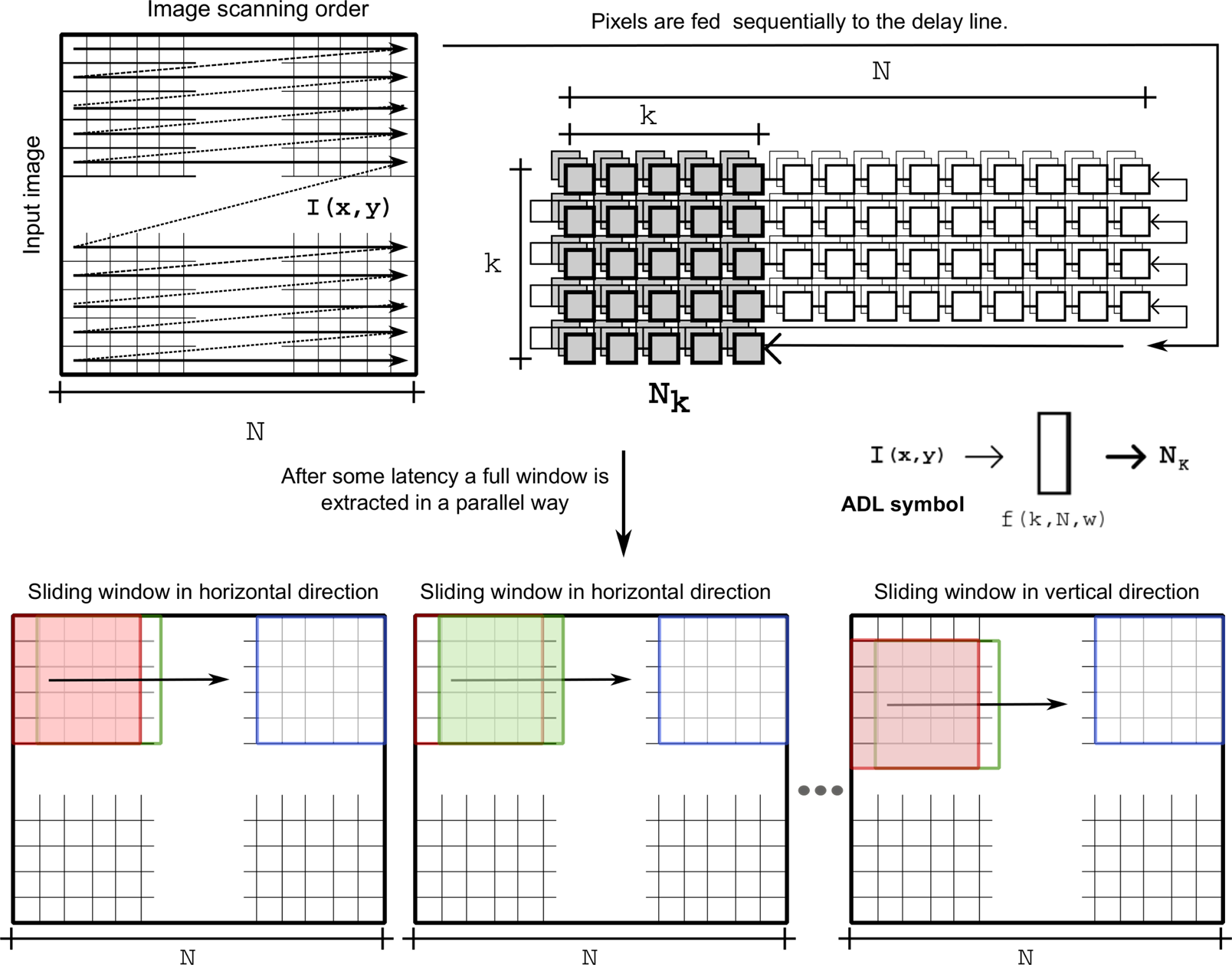
Graphic representation of the storage component for the delay line used to extract windows from an input image and the sliding window effect when the input image is scanned
The response of the Harris feature detector can be computed in three steps:
The partial derivatives can be computed by convolving the input image against the kernels in directions x and y; that is, Ix=Kx * I and Iy=Ky * I. Note that for this operation to produce a result, k × k multiplications and k × k − 1 additions must be computed on the input values. The multiplication and addition operations in the convolution correspond to the scalar function fin and to the local reduction function F, respectively.
The datapath for the Harris feature detector is constructed according to the description given above, and from the primitives introduced in Section 5.1. In Figure 3(a) and Figure 4 the layout of the datapath and the window operator sequencing are depicted. To compute Step 1 and Step 2, windows of scalar values are needed for convolution to be carried out. Moreover, Step 2 must operate on the results produced by Step 1 given that the scalar values a, b and c are calculated from the partial derivatives in the first step. From these observations, a mechanism capable of sourcing windows of scalar values that provides operation sequencing is required.

Datapaths for Harris (a) and SUSAN (b) detectors and for a non-maxima suppression algorithm (c)

Window operator sequencing for Harris detector
Information about precision, as well as control, must be included in the datapath to obtain the architecture for this feature detector. The working precision is especially important given that computations after the Gaussian smoothing are of real type. To overcome real number manipulation and computations fixed-point notation was used. At the end of this section the precision and control of the architecture is discussed.
As with the Harris detector, the response of the SUSAN detector can be calculated in three steps:
The similarity function in Step 1 is a scalar function fin that receives two windows of scalar values as operands, a neighbourhood of pixels NK extracted from an input image I, and a kernel K that outlines a circular shape. The output of fin is a group of logic values that can be arranged in a window, on which a local reduction function F is applied to compute the area n. The SUSAN response can thus be calculated from the scalar values g and n by means of the scalar function fout. The symbolic representation of the datapath for the SUSAN detector is shown in Figure 3(b).
Localization of Interest Points
Non-maxima suppression can be carried out as follows:
The extraction of neighbourhoods in Step 1 becomes straightforward by using the ADL primitive. However, to be consistent with the previous datapaths, a computational element with inputs NK and Knms is connected after the ADL to output the neighbourhood NK. The scalar function fin in the computational element, and the kernel Knms, are such that they allow NK to pass along without modification to its values. The neighbourhood is then reduced by a function F that outputs the value m. Finally, the scalar values m, t and p are operated by the scalar function fout to produce the interesting image I*. The symbolic representation of the datapath previously described is depicted in Figure 3(c).
Unified Architecture for Interest Point Detection and Localization
So far it has been shown that the detection and localization of interest points for target detectors can be described in terms of the threefold operator and the ADL primitives. The computational elements in the threefold operator respond according to the selected algorithm, Harris or SUSAN detector, or the non-maxima suppression, through their fully configurable functions fin, F and fout. The configuration formed by connecting the ADL followed by the threefold operator makes up a pattern that can be identified in every datapath constructed. This pattern is redundant if separate datapaths for each algorithm are considered (see Figure 3). Thus, by reusing this pattern the unification of the Harris and SUSAN detectors, and the non-maxima suppression algorithm can be achieved. However, for such algorithms to coexist an additional component capable of multiplexing and demultiplexing signals is needed. Furthermore, appropriate connections that support the natural increase of bit-width in the scalar values operated throughout the unified datapath must be provided, as well as the control that sustains the correct data flow, as shown in Figure 5. In the figure, the notation aQb denotes the bit-width of the scalar values, a bits of integer part and b bits of fractional part.

Unified architecture for interest point detection and localization. The signal κ passes along the detection response of Harris (κH) or SUSAN (κS) for computing the interest point localization in the architecture. The output response is I*.
In the unified architecture, five ADLs are used to timely deliver neighbourhoods of pixels and cascaded to provide intermediate results to subsequent threefold operators in the datapath. An ADL is active when it supplies neighbourhoods of pixels to the datapath, for which it must be first enabled and its latency time should have passed. In Figure 6 the timing of the ADLs is indicated for the two possible cases of detection in the unified architecture. The blank bars denote latency time, the dark bars the active time of the ADLs, and the grey bars represent the time space at which actual output (processed) pixels are produced. Only one grey bar can be present at any time. In the figure, the latency values can be expressed in terms of the latency L introduced in Section 5.1, that is,

Timing for the ADLs in the unified architecture
Considering an image of height M and width N, the count of clock cycles it takes the architecture to compute the detection and localization of interest points for this image is given by the total processing time TP, which is computed by adding the latency time of the ADLs to the parallel processing time TPP. The parallel processing time in clock cycles for both Harris and SUSAN detectors is given by
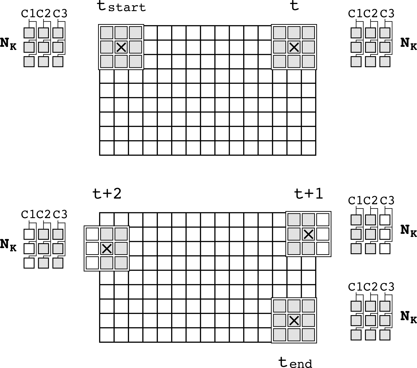
The control module enables and disables columns in the 3×3 extracted neighbourhoods to fit the image size
The proposed architecture was modelled in VHDL, and was organized in modular components designed to support the use of generics in order to provide flexible and reusable building blocks. This modelling approach allowed changes to the architecture, like modifying image resolution, kernels' sizes and coefficients, or the required fixed-point precision, to be simply handled by setting to specific values before synthesis. In order to test and validate the functionality and performance of the unified architecture a testbench was developed (Figure 8).
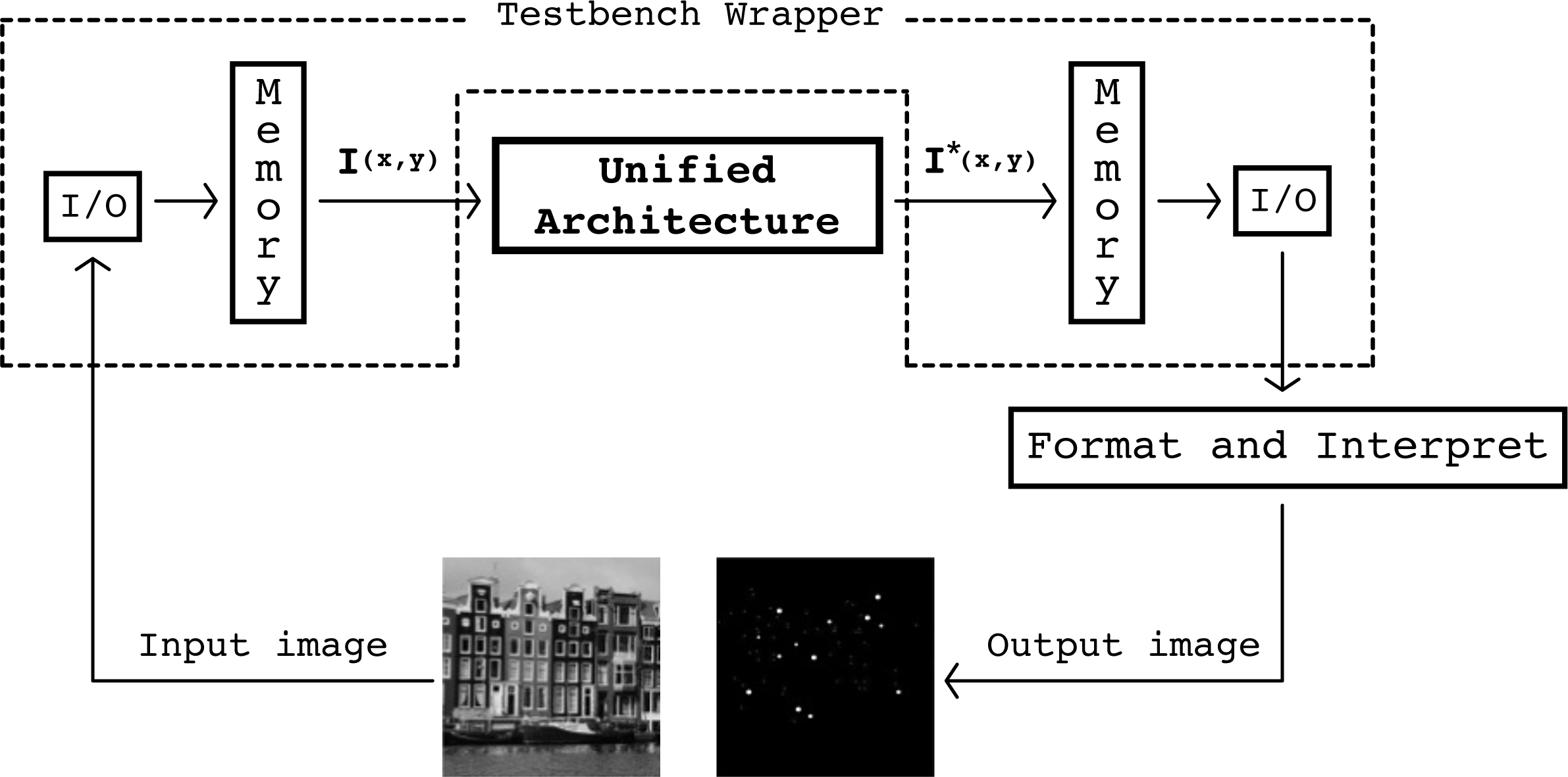
Validation Framework for the proposed architecture
It is important to point out that no simplifications were considered in the design of the architecture. For the SUSAN datapath, the detection and localization of interest points are identical to the response computed in a software implementation as integer arithmetic is used. However, for the Harris implementation, operations are represented in fixed-point arithmetic, and thus some error is expected. We use the peak signal to noise ratio (PSNR) as an indicative of the interest image quality.
To find the bit range within which the corner features are likely to be found, experimental tests were run on 73 images, 24 taken from the Scene Categories Datasets for Computer Vision Research [26] and the remainder from the Feature Detector Evaluation Sequences [27]. The tests were run in Matlab with the objective of finding the upper and lower bit bounds of the corner features range. The upper bound was found to be 40 bits, and the lower bound 19 bits. With these results the output bit-width is reduced from 89 to 21 bits, similar to the 26 bits found in [8]. All 21 bits are taken from the integer part of the number, as shown in Figure 9. In Figure 10, the 89 bit-width Harris response κHis evaluated for the PSNR as bits are cut off to degrade the response. In the figure, the reference image and κH are more alike at higher PSNR values, when fewer bits are cut off from the response. Further experimentation on the datasets made it possible to determine the bit range within which the corners should be found when processing using different sizes of the kernels. Such ranges are presented in Figure 11. The 21 bit-width for the Harris response is indicated in brackets in Figure 10. The response of the architecture for two images taken from the datasets is shown in Figure 12. Information on the image resolution, size of the kernels and parameter values for both detectors are also shown.
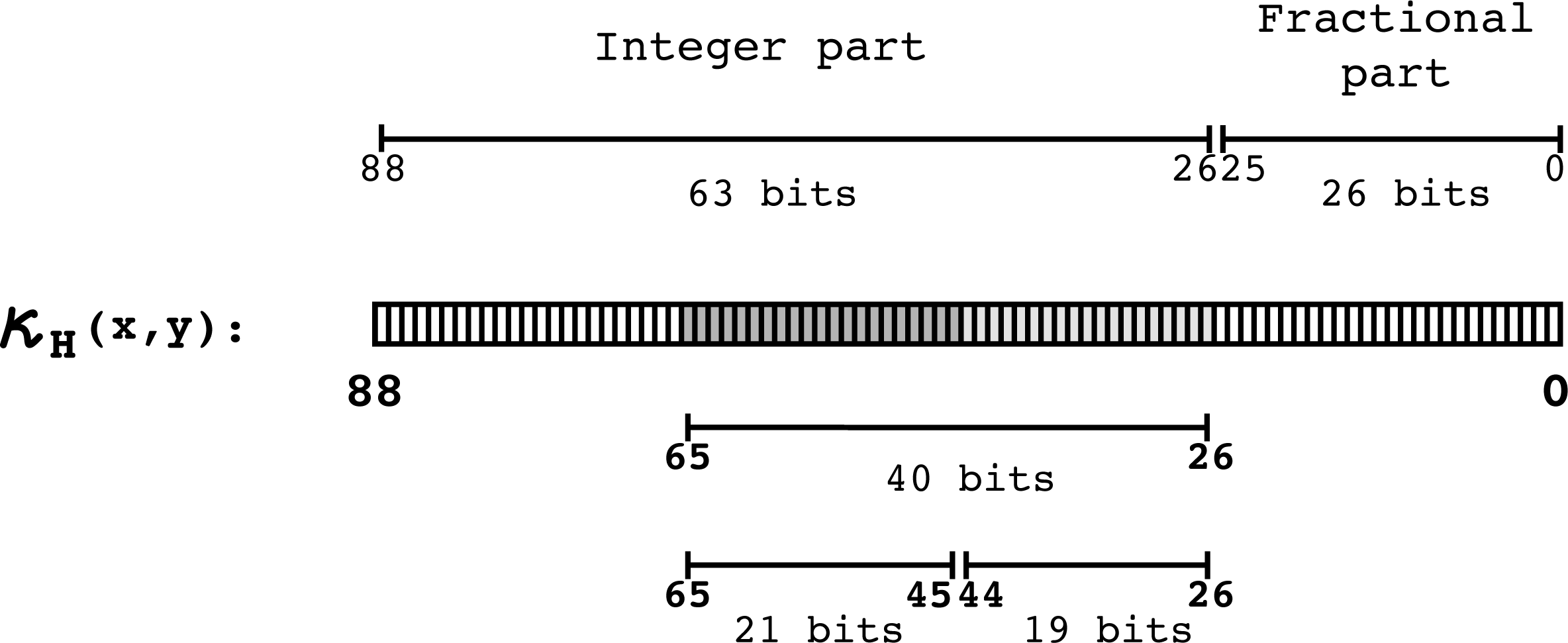
Harris detector output precision. The lower bits stand for values that do not represent corners. Such bits are discarded, conveniently shortening the output width to 21 bits.

Trimmed bits in Harris response and PSNR

Experimental bit-width for the pixels in the Harris response κH. The shaded areas mark the position of the bits that are to be taken when processing an image in the architecture for three sizes of the kernels, 3×3, 5×5 and 7×7.

Functional validation of the unified architecture. The detection response (κ) is shown for Harris and SUSAN detectors. The interest points are superimposed and encircled on the corresponding input images in the last column of the figure.
The Xilinx ISE 14.1 was used for implementing the design on an XC6VLX240t–2FF1156 FPGA device. The place and route results for three sizes of kernel, 3×3, 5×5 and 7×7 are summarized in Tables 2 and 3. In our current implementation, the design does not take advantage of the blockRAM resources for the delay lines; instead, the distributed RAM memory has been used on purpose to target low-cost FPGA-devices, at the cost of some performance. The total power consumption in the unified architecture is 4.75 W at a maximum clock frequency of 50 MHz. The dynamic and static power consumption are 0.29 W and 4.46 W, respectively. If sufficient hardware resources are available, the unified architecture is capable of real-time processing for different sizes of kernel and image resolution, as shown in Figure 13.

Real-time processing in the unified architecture for different sizes of the kernel and image resolution
A throughput of 49.45 Mpixel/s is achieved at a maximum clock frequency of 50 MHz. This performance is sufficient to even support high definition (HD) image formats, e.g., 1080p60 resolution of pixels at a rate of 60 frames per second. The throughput of the proposed hardware implementation is reachable using a current standard desktop PC; however, for embedded image processing scenarios (mobile robots) the use of such PCs is not fully feasible because of size and power consumption issues. For instance, on a desktop computer with a CPU Intel Core2 Duo, 2.4 GHz, and 4 MB, the Harris/SUSAN software implementation on a VGA image takes around 20 ms, i.e., 50 frames per second. According to Possa [12], a CPU-based implementation of the Harris corner detector consumes over 100× more power compared to a custom FPGA-based implementation at 240 MHz clock frequency. The architecture allows flexible processing given that it is fully parameterized and is able to extract image features at run-time using two different algorithms. Compared to the state-of-the-art architectures that target a single feature detector, the accuracy of the unified architecture is not compromised as no modifications or simplifications of the algorithms are carried out beyond the usual fixed-point representation constraint for hardware implementation.
The presented results are mainly discussed for corner detection; however, the architecture performs well for edge detection, as both Harris and SUSAN are able to compute them by selecting the appropriate detector parameters. Furthermore, the architecture can be used to implement other feature detectors. For instance, the architecture datapath can be used for implementing the FAST detector, which is based on the principle that a corner or interest point is dissimilar to its surrounding pixels [11]. In the FAST corner detector, these pixels are compared to the centre pixel in terms of intensity value, specifically the 16 pixels in a Bresenham circle around the point. The point is accepted as a corner if there is a segment of n contiguous pixels classified as brighter or darker, where n is a number between 9 and 16. A set of comparators – scalar function, sequence detector, reduction function – are the main computational units for the FAST implementation. The comparators are already available in the current implementation, and the sequence detector might be implemented as a set of and gates or look-up tables. Further work will be devoted to increasing the flexibility level of the architecture by including more building blocks, and scalar and reduction functions, so as to fully support other feature detectors such as the FAST image interest point detector.
Place and route hardware resource utilization per component in the unified architecture on a Xilinx FPGA XC6VLX240t–2FF1156

Place and route hardware resource utilization on a Xilinx Virtex 6 FPGA XC6VLX240t–2FF1156 for the unified architecture. The results on a 480×640 input image for 3×3, 5×5 and 7×7 sizes of kernel are shown. The values in rackets are the utilization percentages.

In this paper, a flexible hardware architecture for two image feature detectors, Harris and SUSAN, integrated in a single datapath has been presented. The main contribution of this work is the proposal of a design strategy that allows the architecture to adapt to different practical situations by changing the specific detection algorithm at run time. The design strategy is based around two main components – window-based image processing operators and a buffering scheme – commonly found in interest point detectors, to efficiently extract neighbourhoods and allow operator sequencing. The proposed architecture was evaluated on an FPGA platform, and the results have shown a good and competitive performance appropriate for embedded robotic applications where low power consumption, high performance, and compact solutions are required. A throughput of 49.45 Mpixel/s is achieved at a maximum clock frequency of 50 MHz. This performance is sufficient to support high definition (HD) formats, e.g., 1080p60 resolution of pixels at a rate of 60 frames per second. The precision of the hardware implementation is not compromised as algorithm simplifications were not introduced in architecture, but the use of fixed-point arithmetic for the Harris detector. Although the real-time constraint was met, it must be mentioned that some components might be further optimized. Specifically, if balanced stages of a pipeline were incorporated in the first element of the threefold operator the performance of the architecture would substantially improve. Future work will be devoted to enhancing the architecture flexibility and algorithm coverage so that it can be used for other image feature detectors such as the FAST detector. Another possible extension of this work will be the coupling of the architecture to a vision sensor so as to obtain a standalone multi-detector module that can be easily adapted to diverse computer vision applications in robotics.
Footnotes
8.
This research was supported by the National Council of Science and Technology of Mexico (CONACyT) under grants CB-2010-01-150910 and CB-2014-01-237417.