
Abstract
This paper introduces a novel 4-UPS-RPS spatial parallel mechanism, which can achieve three rotation degrees and two translation degrees of freedom. A rigid dynamic model is established and analysis of the parallel mechanism is carried out. The kinematics of the RPS and UPS driving limbs are analysed and the velocity-mapping relationships between the driving limbs and the other parts are built. The load conditions of the parts are analysed, and the rigid dynamic model of the 4-UPS-RPS parallel mechanism is derived by the virtual work principle approach. Using the example of the parallel mechanism movement, a driving forces analysis of the 4-UPS-RPS parallel mechanism is carried out, and the correctness of the rigid dynamic model is verified by numerical calculation and virtual simulation.
Introduction
The spatial parallel mechanism, as a new-structure mechanism, has been applied in many fields, such as machine building, aerospace, and industrial robotics [1–3]. The rigid dynamic model and the analysis of the parallel mechanism, which form the theoretical basis of design, motor control, simulation and performance optimization [4–8], must be investigated.
Due to the closed-loop mechanism, the rigid dynamic modelling of the parallel mechanism is quite complicated. Nowadays, the main existing rigid modelling approaches for parallel mechanisms are the virtual work principle method, the Newton-Euler method and the Lagrange method [9–18]. The virtual work principle method, which has advantages of concision, less redundant information, and high efficiency, has been paid most attention by scholars.
In recent years, due to fewer driving elements, lower cost, and more compact structure, lower-mobility parallel mechanisms have shown great potential for application, and have has gradually attracted the attention of scholars both at home and abroad. The robot in this paper is a new 5-DOF (degrees of freedoms) parallel mechanism invented by our team. According to the screw theory, it can achieve three rotation degrees and two translation degrees of freedom. Since the 4-UPS-RPS (see Figure 1) 5-DOF spatial parallel mechanism has excellent kinematics performance and good application prospects, the parallel mechanism is taken as the object. The rigid dynamics equation of the 4-UPS-RPS parallel mechanism, which consists of four UPS (universal joints/prismatic pairs/spherical joints) driving limbs, one RPS (revolution joints/prismatic pairs/spherical joints) driving limb, a fixed platform and a moving platform, is derived by the virtual work principle in this paper. The driving forces of the 4-UPS-RPS parallel mechanism are analysed by numerical calculation and virtual simulation, respectively.
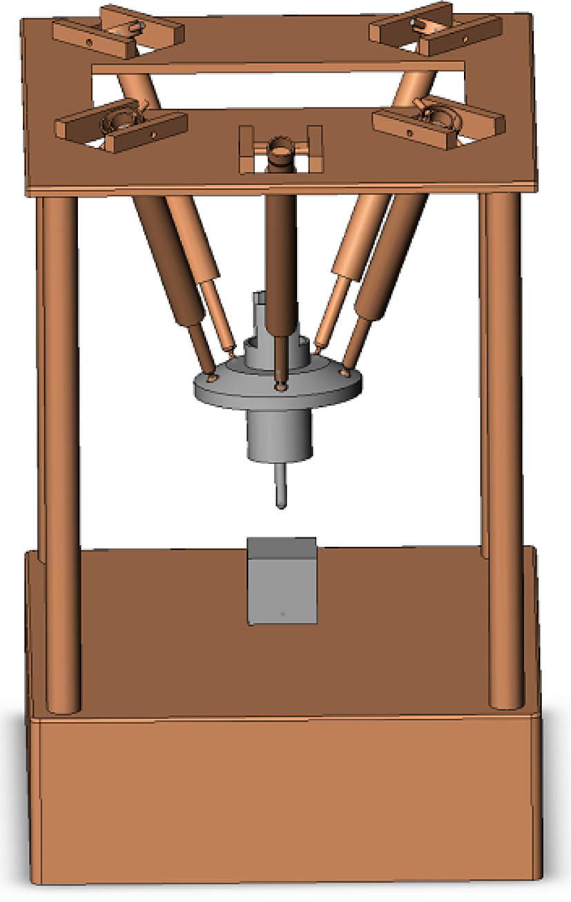
Virtual prototype model of 4-UPS-RPS mechanism
Linear velocities and angular velocities analysis of driving limbs
As shown in Figure 2,
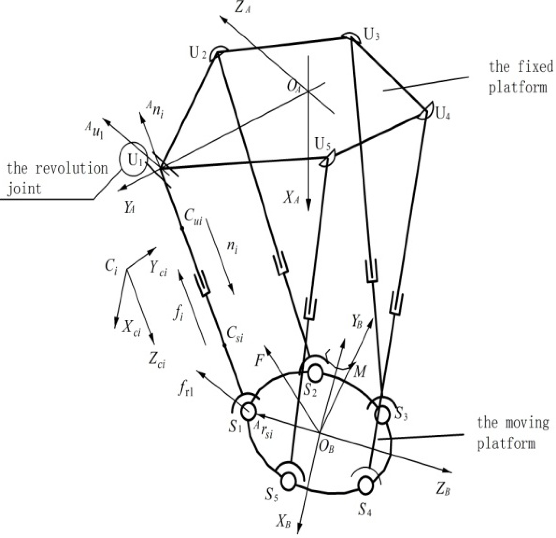
The coordinate systems of the 4-UPS-RPS mechanism

Because the projection of

Equation (2) can be simplified as

where
The value of linear velocity and angular velocity of the RPS limb can be expressed as


where
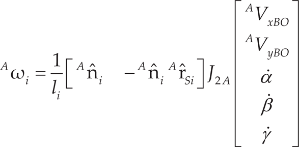
The value of linear velocity and angular velocity of the UPS limb can be expressed as


where
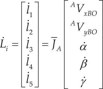
For all the five driving limbs, combining equation (3) with equation (6), we can get

where
Converting

where
R(X, γ) is the rotation matrix, which means the angle γ rotates around the X axis. After the rotation, a new coordinate system O1 − X1Y1Z1 is obtained. R(Y, β) is the rotation matrix, which means the angle β rotates around the Y1 axis. Then, a new coordinate system O2 − X2Y2Z2 is obtained. R(Z, α) is the rotation matrix, which means the angle γ rotates around the Z2 axis.
The spherical joint S1 on the moving platform has no moving displacement along the Z direction, and the velocity of the moving platform along the Z axis is given by

where
The six-dimensions velocity of the moving platform can be expressed as

where

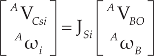
When i=1,…,5, combining equation (8) with equation (11), the linear velocities of five driving limbs can be written as
where
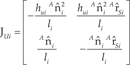
When i=1,…,5, combining equation (11) with equation (7), the linear velocities of five driving limbs can be written as
Calculating the derivative of equation (12), the linear acceleration of each driving limb can be given by

where
a and ∊ are the linear acceleration and angular acceleration of the moving platform, respectively.

Calculating the derivative of equation (13), the angular accelerations of driving limbs are given by

Driving limbs can be divided into two parts. One part is called the oscillating rod, which is connected to the fixed platform, and its barycentre is denoted as
The linear velocities of the barycentre denoted as

The linear accelerated velocities of the barycentre denoted as

The linear velocities of the barycentre denoted as

The linear accelerated velocities of the barycentre denoted as

The relationship between velocities of the barycentre on oscillating rods and velocity of the moving platform is given by

The relationship between velocities of the barycentre on expansion links and velocity of the moving platform is given by
where

According to equation (12), we can get

where
Putting equation (22) into equation (20), we can get

where
Putting equation (22) into equation (21), we can get

where
Force analysis of the moving platform
The inertia force of the moving platform in the fixed coordinate system is given by
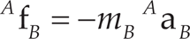
where
mB is the mass of the moving platform.
The inertia moment of the moving platform in the fixed coordinate system is given by

where
The gravity of the moving platform in the fixed-coordinate system {A} is given by

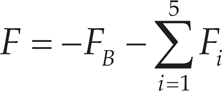
The force and moment of the moving platform in the fixed-coordinate system {A} are written as


As shown in Figure 2, the coordinate system {Ci} is set up on the driving limb RPS. Let the ZCi axis have the same direction with the unit vector of each driving limb; then, the direction of Xi axis is expressed as
The coordinate transformation matrix

For driving limb RPS, where i=l, mu1 is the mass of the oscillating rod. Therefore, the inertia force of oscillating rod in the fixed-coordinate system {A} can be expressed as

Defining

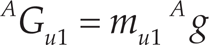
The gravity of the oscillating rod for the RPS driving limb in the fixed coordinate system {A} can be expressed as
For the RPS driving limb, ms1 is the mass of the expansion link. Therefore, the inertia force of the expansion link in the fixed coordinate system {A} can be expressed as

Let

The gravity of the expansion link of the RPS in the fixed coordinate system {A} can be expressed as

For each UPS driving limb, where i=2,…,5, mui is the mass of the oscillating rod. The inertia force of the oscillating rod in the fixed coordinate system {A} can therefore be expressed as

Let

The gravity of the oscillating rod of the UPS in the fixed-coordinate system {A} can be expressed as

For each UPS driving limb, msi is the mass of the expansion link, where i=2,…,5. Therefore, the inertia force of the expansion link in the fixed-coordinate system {A} can be expressed as

Let

The gravity of the expansion link of the UPS in the fixed-coordinate system {A} can be expressed as

In the fixed coordinate system {A}, firstly, the external forces on the main components of the spatial parallel mechanism should be simplified to the six-dimensional resultant force vector on the barycentre of each part. Then, the equivalent driving force, which is converted to five driving limbs, should be calculated.
The equivalent driving forces on five driving limbs are given by

The external forces on each driving limb UiPiSi(i=1,…,5, when i=1, the driving limb is RPS) converted to five driving limbs can be expressed as

According to the virtual work principle, the driving forces of five driving limbs for the spatial parallel mechanism are equal to the equivalent driving force. We can then get

Then, the dynamic model of the spatial parallel mechanism can be expressed as
where i = 1,2,3,4,5
F = [f1 f f3 f4 f5]T is the driving forces of five driving limbs.
Structural parameters of the 4-UPS-RPS spatial parallel mechanism
The mass of the moving platform is 36.28 kg. The distance between the barycentre on the oscillating rod and the Hooke hinge (or the revolution joint) on the fixed platform is denoted as hui, and hui =0.378 m. The mass of the oscillating rod is denoted as mui, and mui =26.15 kg. The distance between the bary centre on the expansion link and the spherical joints on the moving platform is denoted as hsi, and hsi =0.452 m. The mass of the expansion link is denoted as msi, and msi =8.45 kg. The rotational inertia of the moving platform (unit: kg · m2) is denoted as
Dynamic analysis results of the spatial parallel mechanism
The motion of the 4-UPS-RPS spatial parallel mechanism is described as follows:
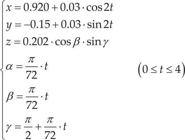
According to the rigid dynamic equation (46), the driving force of the 4-UPS-RPS spatial parallel mechanism under no-load condition, as acquired by numerical calculation, is shown in Figure 3(a), and the driving force of the 4-UPS-RPS spatial parallel mechanism under no-load condition, as acquired by the simulation of ADAMS2010, is shown in Figure 3(b). When the moving platform is under load with force (unit: N)

Five driving forces of spatial parallel mechanism under no-load condition

Five driving forces of spatial parallel mechanism under loading condition
According to Figures 3(a), 3(b), 4(a) and 4(b), the theoretical calculation results obtained by Matlab7.0 are basically consistent with the simulation results obtained by ADAMS2010; therefore, the correctness of the theoretical calculation and the virtual simulation is verified.
The kinematics of the RPS and UPS driving limbs of the 4-UPS-RPS spatial parallel mechanism were analysed and the relationships between the velocity of the parts and the velocity of the driving limbs were established. The rigid dynamic equation of the 4-UPS-RPS spatial parallel mechanism was established. The dynamic equation was analysed by numerical calculation and virtual simulation, and its correctness verified.
Footnotes
7.
This research is supported by the National Natural Science Foundation of China (grant no. 51005138, 51375282 11272167), the Shandong Young Scientists Award Fund (grant no. BS2012ZZ008), the Programme for Changjiang Scholars and Innovative Research Teams in Universities (IRT1266), Taishan Scholarship Project of Shandong Province (No. tshw20130956), the Science Foundation of SUST (grant no. 2011KYJQ102), and the project of Jiangsu Key Laboratory of Digital Manufacturing Technology (grant no. HGDML-1104).