
Abstract
This paper proposes a new robot controller for motor-system rehabilitation. The proposed controller simultaneously realizes rehabilitation motion tracking and force generation, as predefined through a musculoskeletal model-based optimization process. We introduce control parameters of weighted control action priorities for the motion-tracking and force-generation tasks, based on the position-tracking error. With the weighted control action priorities, the robot accords higher priority to motion tracking at the robot end point when the position-tracking error is larger than a threshold value, and to force generation when the position-tracking error is smaller than a threshold value. Smooth motion trajectory has to be designed and applied in robot-based rehabilitation. Through simulations and experimental results, we show the usefulness of the proposed control method.
Keywords
Introduction
Robots are expected to supplement and provide alternatives in the current roles of physiotherapists in rehabilitation centres, allowing patients to conduct rehabilitation tasks in an accurate and stable manner, since robot-aided rehabilitation includes tracking of complex motion and generation of force at the end point, fast time response characteristics, repeatability of behaviour, and quantitative evaluation of patient motion by the use of a force and/or motion sensor. Modern designs of physical therapy programmes often use musculoskeletal models of body segments and computer simulation of the exerted muscular forces as a tool for analysis of the effect of the planned physical exercises. Musculoskeletal models accelerate the process of refinement of the developed programmes and facilitate the identification of the conditions that maximize the treatment effect. The development of accurate musculoskeletal models has included research on muscle forces [1], investigation of the response of the joints to the external load applied to them [2], and exploration of the passive reaction forces and muscle forces generated during exercising in closed and open kinetic chains [3–4].
In [5–7], the advantages of robot-aided rehabilitation over conventional therapist-based rehabilitation methods have been illustrated in terms of recovery of motor function, physical balance support in specific tasks through reinforcement learning, patient-centred rehabilitation, and enlargement of joint range of motion. MIT-Manus [8] and Lokomat [9] are well-known rehabilitation robots. MIT-Manus introduced the impedance controller to assist subjects to track a desired motion trajectory in an accurate manner, where the impedance field is provided to find the relationship between the subject's hand motion and the force generated by the robot. Lokomat, a gait-training system developed by Hokoma, lifts a patient's body to hold up part of the patient's weight, and controls the speed of the subject's passive walking based on his/her gait functional level by changing the treadmill speed.
It is important in robot-aided rehabilitation to choose suitable motion and external force trajectories according to the symptomatic states and damaged segments of the patients. In motor-system rehabilitation for enlargement of joint motion range, muscle training and so on, it is desirable to load and unload some specified muscles selectively. For example, muscles around damaged segments should not actively move in the initial rehabilitation stage to prevent secondary disability. On the other hand, we need to intensify muscle strength of weakened muscles of patients who are in long-term rehabilitation or in old age by loading appropriate forces on the specified muscles.
An impedance controller was proposed by Hogan [10] to establish a desired dynamical relationship (i.e., impedance) between the robot end point and the force the robot exerts on the environment. Advantages of the impedance control method include simplicity and use of the impedance field. By constructing the impedance field determined by the impedance coefficients around the time-varying reference rehabilitation motion trajectory, we can allow the patient to perceive the reference motion; by constructing the impedance field intensity, we can also design mechanical interaction between the robot and the patient.
On the other hand, general industrial robots with six or seven joints have limited motional degree-of-freedom (DOF), and cannot realize simultaneous motion tracking and force generation. From the viewpoint of motional DOF, 12 joints (six joints for position/posture tracking, and another six joints for force/moment generation) are required for exact simultaneous motion tracking and force generation. However, robots with 12 joints are structurally too complex and become expensive for application to disabled patients. In this study, we target the development of a motor-system rehabilitation robot with a limited number of joints, which realizes a tailor-made rehabilitation task. Although impedance control-based position or force controllers or hybrid controllers which apply position and force control modes independently with respect to each axis defined at the contact point have been successfully applied to various systems, simultaneous control of position tracking and force generation at the end point or at the contact point between the robot and the patient has not been proposed.
This paper proposes a new controller for the robot which can realize a motor-system rehabilitation task predefined through a musculoskeletal model-based optimization process [11–15]. The proposed controller simultaneously realizes rehabilitation motion tracking and force generation with a limited joint number of the rehabilitation robot. With the proposed controller we can realize tasks whose control variable number (e.g., joint angles of all joints plus six axes’ forces at the endpoint) is larger than the joint number of the manipulator for motion tracking and force generation. We introduce control parameters of weighted control action priorities of the motion-tracking task and force-generation task, based on the position-tracking error. With the weighted control action priorities, the robot increases (decreases) the priority parameter of motion tracking (force generation) at the robot end point when the motion-tracking error is larger than a threshold value, and also increases (decreases) the priority parameter of force generation (motion tracking) when the motion-tracking error is smaller than a threshold value. Using simulations and experimental results, we show the usefulness of the proposed control method.
Impedance Control
Different types of robot control method have been proposed in the literature [16], which can be classified as follows: (1) hybrid control [17, 18, 21], which allocates force control axes and position control axes independently; (2) impedance control [19], where there is a linear constraint of the contact force and the position at the end point of the robot manipulator. The compliance control method, which uses a simplified impedance model [20], can also be included in the impedance control category. In order to allow a robot to realize a task which involves contact with an environment, a general strategy is to apply compliance/impedance control to the system for a large position/motion error, and to switch to force control right after the end point of the robot comes into contact with the environment. A similar strategy can be applied to the rehabilitation robots: when the position error is larger than a threshold value, we can apply position-mode impedance control with high impedance field around the desired end point of the robot. When the position error is smaller than a threshold value, we can apply force-mode impedance control, whereby a desired force can be generated by modifying the impedance parameters. Therefore, in this study, we develop a new controller for achieving both motion tracking and force generation at robot end points, based on the combination of both position- and force-mode impedance control.
The impedance control modes are as follows.
Position (control) mode:

Force (control) mode:

Here, r is the position of the end point of the robot manipulator, rd is the desired value of r,
In the position control mode of (1), the position, velocity and acceleration of the robot end point are determined in proportion to the force generated by a human. On the other hand, in the force control mode of (2), the robot generates contact force Fd at the end point in proportion to the difference between the velocity of the robot end point and its desired value. The impedance coefficient matrices for inertia, viscosity, and elasticity can be virtually constructed such that the patient may feel as if the damper and spring specified by the viscosity and elasticity matrices were connected to the end point of the robot, whose mass is determined by the inertia matrix.
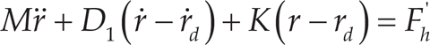
It is notable that the methods reported in [11–15] design the rehabilitation task for a specific patient based on his or her musculoskeletal model. They represent static rehabilitation-task design, in the sense that they ignore the effects of voluntary movement of the patient in rehabilitation training. In an actual robot-assisted rehabilitation environment, however, there is an inescapable interaction of forces between the patient and the robot. Therefore, we have to consider the patient's movement and the forces generated not only by the patients but also by the robots in the form of the counteraction for the motion trajectory error. Especially on the robot side, a counter action should be established in order that the rehabilitation effect that is expected for the static rehabilitation task may be acquired through a proper control framework even in the dynamic rehabilitation environment. Since our goal is not the exact control of the rehabilitation robot in a static situation, but rather the control of the patient's muscle forces associated with the movement of the body motion, we need to modify (2) as follows:


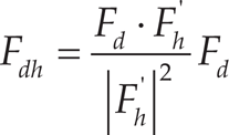
In (3), F'd is the modified force reference, and F'h is the value of Fh at the previous sampling instant. Fig. 1 shows the relationship between F, F', and F'h. By selecting F'd in force control mode, we can relieve subjects’ force generation by having the robot generate the force in the direction of F'dh, which amounts to the projection of F'd on F'h. As shown in Fig. 1, when the force is generated by the human subject, F'h is larger than the projected component of Fd on F'h (Fdh in Fig. 1); the robot generates F'dh in the direction of F'h, which relieves the human force generation at the next sampling instant in that direction. In a similar way, when Fd contains no F'h direction component, the robot generates F'dn, which makes the human subjects generate muscle forces in the normal direction of F'h.

The relationship between Fd, F'd, and F'h
While we conduct the experimental tests based on the robot-assisted rehabilitation, on the other hand, the measurement value provided by the force sensor installed at the contact point between the patient and the robot is the subtraction of the resultant force of the forces generated by each actuator at the robot joints from the resultant force of the forces generated by each muscle of the patient musculoskeletal system. We cannot directly control the force generated only by the patient at the contact point between the patient and the robot. However, under a certain condition where both the robot and the patient are constrained to a certain behaviour for realizing the trajectory-tracking task, the force-sensor measurement value that comes from the result of the force interaction between the robot and the patient may be used to control the muscle force generated by the patient in an indirect manner. Therefore, in this study, we introduce a new variable, “Fr“, to represent the force interaction between the robot and the patient who is conducting the trajectory-tracking task in a robot-assisted rehabilitation environment.
By controlling the impedance parameters virtually constructed at the end point of the robot, we can realize motion tracking of the rehabilitation trajectory and force generation at the robot end point.
For smooth switching of control modes, we introduce s hybrid position/force control mode that is placed between position control mode and force control mode. In the hybrid position/force control mode, virtual impedance matrices are updated for a smooth mode change. In this subsection, we propose the active rehabilitation hybrid position/force control mode. In active rehabilitation hybrid control mode, the motion-tracking performance depends on the effort made by the patient for the motion tracking.
The hybrid position/force control mode for active rehabilitation is expressed as follows:


In (7), Γ is a diagonal matrix whose diagonal elements are (α1, α2, α3); dimensionless coefficients are determined as follows:

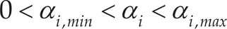
Therefore, αi is constrained by 0 ≦α i ≦1. Here, Emax, i is the maximum position error:

While αi is set to 1, the i th axis in the base coordinate system of (7) is controlled in the position control mode of (8), and while αi is set to 0, the axis is controlled in the force control mode of (9); finally, while 0 <α i < 1, the axis is controlled in the hybrid position/force control mode. By limiting the upper bound of αi, we can define an allowable size of the maximum position error, Emax i. If the patient's motion goes over the upper bound, the position control mode is applied only by the impedance field of (1) in order to make the end point of the robot trace the desired motion trajectory. When αi is set to 0 or 1, and the velocity and acceleration of r are significantly large; however, the equation (7) cannot hold. Therefore, we confine the range of αi as follows:
Fr, the linear combination between Fh and F, represents the force relation between the robot and the patient. When the tracking error (between the position of the end point and its desired value) is large, the robot tries to increase the trajectory-tracking performance with an increased value of Γ, while, when the tracking error is smaller than a threshold value, it tries to increase the force-generation function with a decreased value of Γ. In the form of (7), we can represent the control activity of a robot in robot-assisted rehabilitation. As the trajectory-tracking performance increases, the position-control-mode ratio of Γ increases, which helps improve force-generation performance; as a result, both position-tracking performance and force-generation performance can be adequately realized.
Updating of αi implies change of priorities in control action of the system, and can be implemented in the system by updating virtual impedance parameters as follows:


We show the block diagram of the hybrid-mode impedance control system in Fig. 2, where FΔ is the measurement error of the force acting on the robot end point, in other words, the contact point between the patient and the robot, and η is the disturbance that comes from nonlinear robot dynamics. z1, z2, z3 are defined as follows:


The block diagram of the active-rehabilitation hybrid control mode is shown in Fig. 2. The impedance field constructed around the rehabilitation motion trajectory allows patients to perceive the reference motion trajectory. Since the patients are subjected to external forces, however, it is hard for them to perceive the reference motion trajectory from the beginning of the rehabilitation session. Therefore, it is desirable to apply a passive-mode rehabilitation task at the initial stage of the rehabilitation session, where the patient moves his or her limb passively until he or she can fully perceive, confirm and memorize the reference motion trajectory with the help of the screen that displays the reference motion trajectory and actual motion trajectory traced by the subjects. Then, we can apply the active-mode rehabilitation task, whereby patients can perceive reference rehabilitation motion by the impedance field.
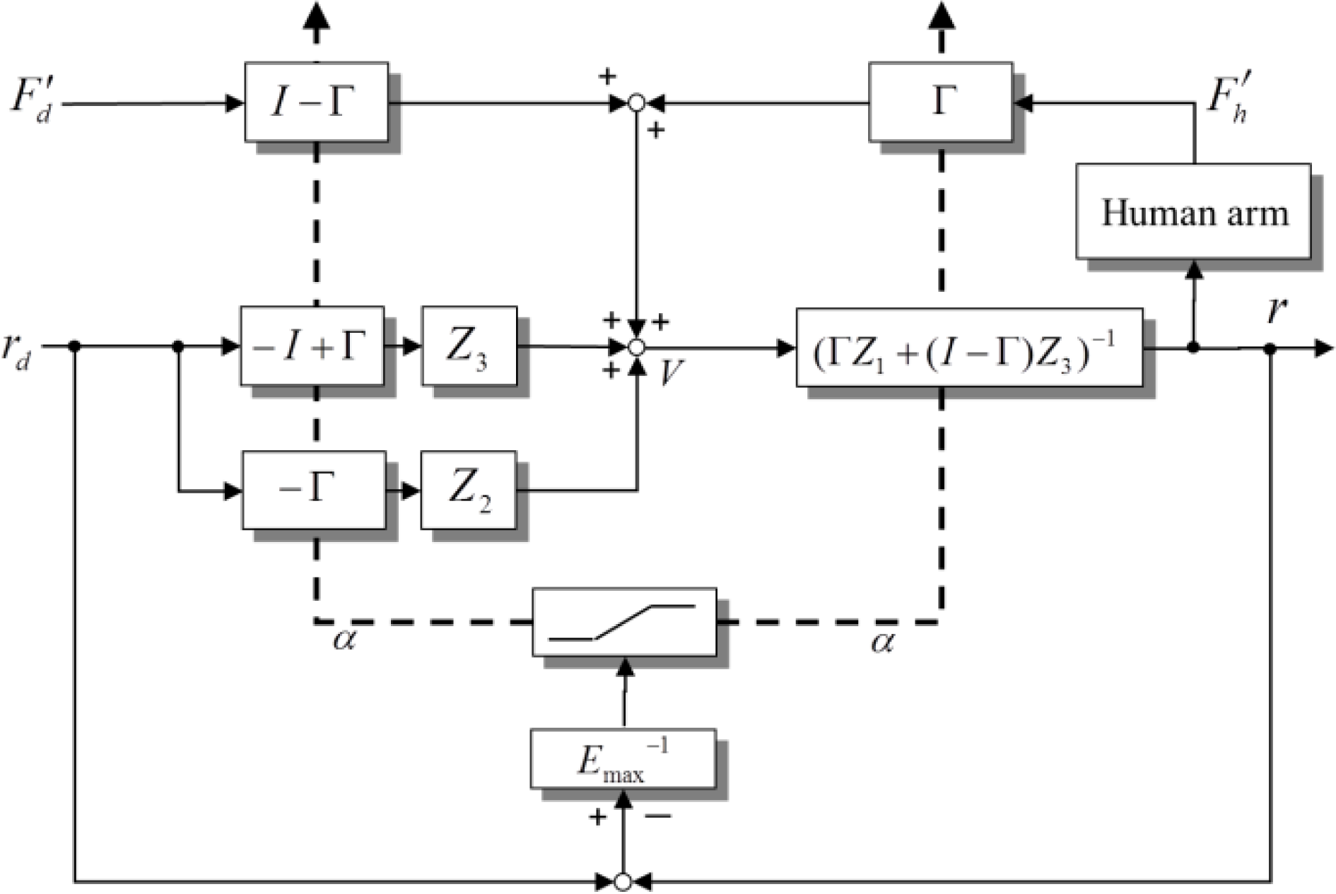
Active-rehabilitation hybrid-mode impedance control system
In order to confirm the effectiveness of the proposed controller for an active-motor-system rehabilitation robot, we carried out simulations and experiments. The goal of the simulations/experiments was to evaluate the performance of the proposed hybrid position/force control mode for the active rehabilitation system for realization of the motor-system rehabilitation task developed by the method described in [15]. Fig. 3 shows the experimental environment, where a dynamical model of a six-DOF robot manipulator was used for simulation. We assume a subject is on a chair two metres away from the monitor, gripping the knob with his or her dominant hand. The target value of the tracking task and its actual value are shown in the monitor. A six-axis force sensor and the knob were connected to the end of the manipulator so that the subject could manipulate the knob to change the current position value of the end effector. The subject was asked to manipulate the cursor shown in the monitor to track the target value with the knob. We used the robot model PA 10-6C-ARM (Mitsubishi Heavy Industries, Ltd.; see Appendix for robot parameters), whose x, y, z axes in the coordinate system of each joint were defined in relation to the frontal direction, the direction away from the body core on the frontal plane, and the height direction, respectively. The first, fourth, and sixth joints from the base coordinate system rotated around the z axis, and the second, third, and fifth joints from the base coordinate system rotated around the y axis. Each length of the link i between the i th joint and the i+1 th joint was as follows:

Experimental environment

In Fig. 4 (a) to (d), we first show the simulation result of the proposed controller for active rehabilitation when the impedance parameters of robot are set as follows:
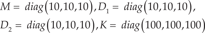
Fig. 4 (a) compares the x-, y-, and z-axis positions at the robot end point and the desired values. Fig. 4 (b) compares x-, y-, and z-axis velocities at the robot's end point and the desired values, designed as in [15].
In Fig. 4 (a) and (b), solid lines and dashed lines imply actual values and desired values, respectively. We set the initial values of rx, ry and rz to 10 [cm], 0 [cm], and −80 [cm], respectively. Although the initial values of rx and rz are greatly different to the desired values, the values soon converge. After about three seconds from the start, however, the value of r shows good tracking performance.
Fig. 4 (c) compares Fr, that is, the linear combination of Fh and F'd in the form of (4) in the x, y, and z axis, and the modified force references F'd, and the forces generated by the patient Fh and their desired forces Fd, designed as in [15]. Here, Fr was computed by (4). In the proposed controller for active rehabilitation, Fr showed good tracking performance for F'd. The tracking performance of Fr depends on the impedance parameters.
Fig. 4 (d) shows x-, y-, and z-axis values for α and η. Since we used strong impedance parameters for K in this simulation, the position tracking performance was very good after about three seconds from the start. From this moment, the value of α in each direction was set to around its minimal value, α min .
In order to confirm the usefulness of the proposed active rehabilitation method, we now show the experimental results. We used a serial manipulator with seven degrees of freedom. At the end point of the manipulator, a six-axis force/torque sensor was attached between the robot end-effector and the knob. The motion of the manipulator was restricted on the vertical plane. The monitor was set 1.5 metres in front of the subject sitting on the chair. During the experiments, the subject was asked to concentrate on the monitor.

Simulation result of active rehabilitation with M = diag(10,10,10), D1 = diag(10,10,10), D2 = diag(10,10,10), K = diag(100,100,100)
For simplicity, we did not use a rehabilitation trajectory designed through a musculoskeletal model-based optimization process, and confined the focus of this experiment to the verification of simultaneous tracking characteristics in position and force generation. The reference trajectories were set as follows.
The desired x-axis and z-axis trajectories:
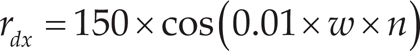

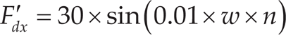
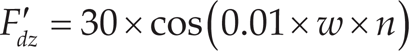
Here, n implies the time elapse. The desired x-axis and z-axis force trajectories:
The impedance parameters in this study were set as follows:

Experimental result of the proposed method

The robot manipulator used was a PA-10, manufactured by Mitsubishi Heavy Industries. Because of the constraint on the communication ports on the computer, we could not use a three-dimensional position trajectory or a three-dimensional force trajectory as the rehabilitation task. We need four channels for the data communication of rx, rz, Fx, Fz to the computer, and another two channels for the data communication of vx, and vz. In Fig. 5(a), “actual value” and “desired value” imply r and rd, respectively. In Fig. 5(b), “actual value” and “desired value” imply Fr and F'd, respectively. Here, Fr is directly measured by the force sensor manufactured by NITTA Corporation. The subject was a 35-year-old female. She started to use the knob to control the manipulator from 1.2 seconds after the start. As we see in the experiment result, a certain level of position-tracking error was observed due to disturbances such as sensing error and joint friction, even in the time zone from the first 1.2 seconds. A certain level of force-generation error is also seen in Fig. 5 (b). The reason for the force-generation delay can be considered to be due to the robot's late time response characteristics for the input signal and the subject's reflex characteristics. However, we can observe the consistent simultaneous tracking characteristics in position and force generation.
Only two important rehabilitation processes have been reported: (1) cognitive rehabilitation, and (2) muscle rehabilitation. The former is the process of relearning cognitive skills that have been lost or altered as a result of damage to brain cells/chemistry. If skills cannot be relearned, then new ones have to be taught to enable the person to compensate for their lost cognitive functions. The latter is the process of restoring normal muscle function by activating and strengthening weakened muscles. These two rehabilitation processes have been widely and generally used in actual clinical practice, where cognitive rehabilitation has been applied for people with neuronal dysfunction and muscle rehabilitation for aged people with weakened muscle function or people with neurological function restored to an extent through cognitive rehabilitation. It is especially important to undergo rehabilitation for aged people who lie in bed for a long time since they can easily lose their muscle volume.
Several rehabilitation robots in the category of cognitive rehabilitation have been reported, while rehabilitation robots in the category of muscle rehabilitation are rare. Cognitive rehabilitation robots only involve positional interaction between a rehabilitation robot and a human subject, but muscle rehabilitation robots involve both positional and dynamic interactions between the two. For realization of a muscle rehabilitation robot, we first design a rehabilitation task which maximizes the use of specific muscle(s) and keeps the force acting on a specific joint under a certain level; secondly, we develop a force-position simultaneous control method so that the designed rehabilitation task may be realized. This is the role of muscle rehabilitation robots. Since the rehabilitation task can be defined with position trajectory and force trajectory, both force- and position-tracking performances are indispensable. This means that force- and position-tracking performances are not as effective as in the case of cognitive rehabilitation therapy. As is now understood, the proposed simultaneous position/force control method is essential methodology for realization of muscle rehabilitation tasks.
The effectiveness of the proposed method is evaluated in [11, 13–15] through numerical experiments, which can be summarized as follows: by using both rehabilitation motion and force at the end-effector, we can achieve better rehabilitation effects; conventional rehabilitation tasks do not handle directly both rehabilitation motion and force at the end-effector. In our past publication [15], we proposed a simultaneous reference-trajectory generation method for both rehabilitation motion and force at the end effector by direct use of a musculoskeletal model of the patient, and demonstrated the effectiveness of the conventional method. This paper proposes a new method in rehabilitation-robot control, which realizes simultaneous tracking performance of rehabilitation motion and force at the end-effector.
The sensor measurement value Fs at the end point of the rehabilitation robot is the subtraction between the resultant force Fr of the forces generated by each actuator at the robot joints, and the resultant force F'h of the forces generated by each muscle of the patient's musculoskeletal system. However, we cannot measure both forces simultaneously in a direct manner. Therefore, we proposed a new model in the form of (4), where F'h is the value of Fh at the previous sampling instant and the value of F'h can be calculated from (7) with the force sensor measurement value Fs.
With the estimated value of F'h, we set the modified force reference F'd. Based on the trajectory-tracking error, we calculate the value of G, which yields the design of the robot impedance parameters. As a result, we can achieve good position-tracking performance and force-generation performance at robot end point.
Conclusion
We have proposed a hybrid-mode impedance controller for position tracking and force generation in motor-system rehabilitation. The proposed controller simultaneously realizes rehabilitation motion tracking and force generation with a limited joint number of the rehabilitation robot. With a six-axis serial manipulator, we realized three-dimensional position/velocity and three-dimensional force generation. For strict realization of this problem, we generally need to use a nine-axis robot manipulator.
We introduced control parameters of weighted control action priorities of the motion-tracking task and force-generation task, based on the position tracking error. With the weighted control action priorities, the robot puts higher priority on motion tracking at the robot end point when the position tracking error is large, and also on force generation when the position tracking error is smaller than a threshold value. Smooth motion trajectory in robot-based rehabilitation has to be designed in full consideration of applicability by robots. Through simulations and experimental results, we have shown the usefulness of the proposed control method.
Footnotes
Appendix
The total number of PA-10 actuators we used for the experiment was seven, and at each axis the coordinate systems were defined in accordance with the general Denavit-Hartenberg method, where the parameter ai is the distance from zi to zi+1 measured along xi, αi is the angle between zi and zi+1 measured about x, and di is the distance from xi−1 to xi measured along z, as follows.
Denavit-Hartenber parameters of PA-10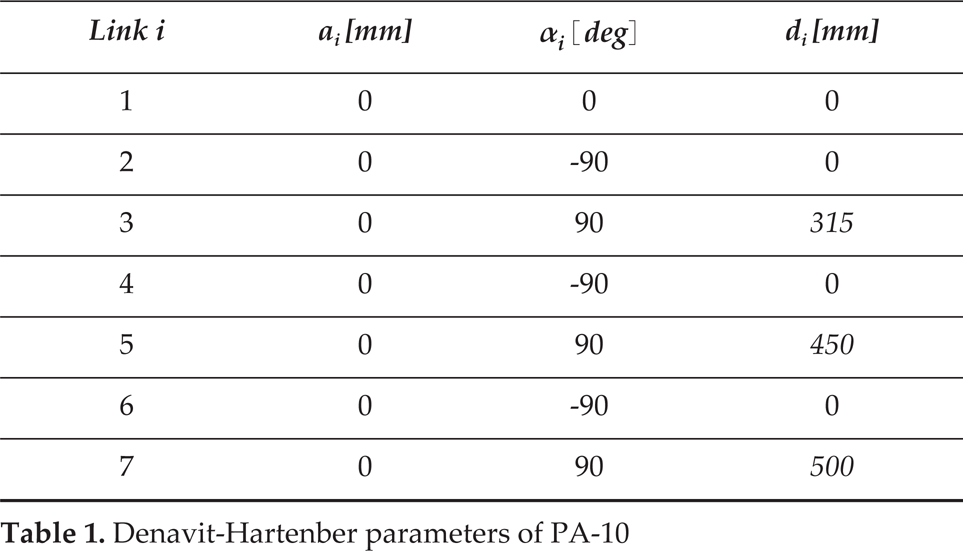
Link i
ai [mm]
αi [deg]
di [mm]
1
0
0
0
2
0
−90
0
3
0
90
315
4
0
−90
0
5
0
90
450
6
0
−90
0
7
0
90
500
Joint operating ranges and maximal operation speeds are as follows.
Joint ranges and operation speeds of each actuator
Axis index
Limit [deg]
Max operation speed [rand/sec]
axis 1
−360 < θ1 < 360
6.28
axis 2
−165 < θ2 < 165
6.28
axis 3
−255 < θ3 < 255
6.28
axis 4
−137 < θ4 < 137
2
axis 5
−174 < θ5 < 174
2
axis 6
−91 < θ6 < 91
1
axis 7
−177 < θ7 < 177
1