
Abstract
In this article, a generalized proportional integral (GPI) control approach is presented for regulation and trajectory tracking problems in a nonlinear, multivariable quadrotor system model. In the feedback control law, no asymptotic observers or time discretizations are needed in the feedback loop. The GPI controller guarantees the asymptotically and exponentially stable behaviour of the controlled quadrotor position and orientation, as well as the possibilities of carrying out trajectory tracking tasks. The simulation results presented in the paper show that the proposed method exhibits very good stabilization and tracking performance in the presence of atmospheric disturbances and noise measurements.
Keywords
Introduction
Unmanned aerial vehicles (UAVs) have attracted considerable interest for a wide variety of applications, including meteorological observation, fire monitoring and patrolling, to military purposes such as reconnaissance, monitoring and communication [1]. UAVs can be classified into four main categories based in their aerodynamic configuration [2]: (a) fixed-wing UAVs, which require a runway to land and take-off; (b) rotary-wing UAVs, which are able to land and take-off vertically and which have high manoeuvrability; (c) blimp UAVs, which appear like balloons or airships and which ensure lift by their helium-filled body; and finally (d) flapping-wing UAVs, which are inspired by flying insects and which can perform vertical take-off and landing. Nevertheless, rotary-wing platforms have captured a lot of attention in research projects because they present a number of advantages with regard to other UAV platforms. Their high manoeuvrability and ability to vertically take-off and land, as well as the capacity to fly in tough conditions to reach specified areas, make them ideal vehicles for these applications. Among rotary-wing UAVs, a new sub-classification can be considered [3]: (a) a single rotor is composed by a main rotor on the top and another rotor at the tail to achieve stability (a similar configuration to a helicopter); (b) a coaxial presents two propellers mounted in the same shaft rotating in opposite directions; (c) a quadrotor consists of four rotors fitted in a cross-like configuration; and (d) a multi-rotor consists of six or eight rotors. They are very agile and are able to fly even when a rotor does not work properly (there is redundancy due to the large number of rotors). We should note that, according to this classification, the quadrotor configuration has been the most widely used.
The quadrotor platform has four powerful rotors, each one of which has independent rotational speed, mounted in a square formation equidistant from the centre. The variation in the speed of the rotors generates the thrust and acceleration in the desired direction. Among the advantages of this platform are low cost, usability and ease of transportation, and it is also able to move at low speeds to ensure good quality images. However, despite the advantages of quadrotors with respect to other UAV platforms, the control of a quadrotor is a challenge due to its high manoeuvrability, its highly coupled multivariable dynamics of a nonlinear nature, and its underactuated condition, taking into account that it has six degrees of freedom (three for position and three for attitude) and only four rotors. For this reason, control techniques for these UAV platforms have witnessed rapidly expanding research to achieve not only autonomous hovering and orientation but also trajectory tracking [4]. Zuo [5] studied the command-filtered backstepping technique in order to stabilize a quadrotor's attitude without calculating analytically the pseudo-control signal derivative, as well as to decrease the dependent degrees of the analytic model. In Bouabdallah et al. [6], the application of two different approaches is presented, namely a PID approach assuming a simplified dynamics, and the LQ technique based on a more complete model. La Civita [7] proposed a robust control approach combined with linear rotorcraft models. Madani and Benallegue [8] presented a backstepping control strategy taking into consideration that the quadrotor can be divided into three subsystems: an under-actuated subsystem, a fully-actuated subsystem, and a propeller subsystem. Waslander et al. [9] presented two design approaches-integral sliding modes and reinforcement learning – for the altitude control loop. Both techniques resulted in stable controllers with similar response times, showing a significant improvement over linear controllers (which failed to stabilize the system adequately). Formentin and Lovera [10] developed a control law based on the differential flatness property of the position dynamics and the linearization of the system via feedforward and a passivity-based scheme. Furthermore, Gautam and Ha proposed in [11] a self-tuning fuzzy PID controller based on an EKF algorithm for the attitude and position control of a quadrotor. In a recent paper, Chen et al. described in [12] a reconfiguration control scheme for a quadrotor helicopter with actuator faults via adaptive control and combined multiple models. Sira-Ramrez studied in [13] an active disturbance rejection control scheme for efficient regulation and trajectory tracking tasks in a nonlinear, multivariable quadrotor system model. Escareño et al. [14] developed a nonlinear control strategy based on nested saturations that stabilizes the state of the quadrotor around the origin.
Recently, generalized proportional integral (GPI) controllers have demonstrated good performance in the control of nonlinear systems. GPI control has been found to present a better dynamic response than PID control in terms of the settling time while exhibiting a greater degree of robustness regarding disturbance rejection [15, 16]. GPI control sidesteps the need for traditional asymptotic state observers and directly proceeds to use, in a previously designed state feedback control law, structural state estimates in place of the actual state variables. These structural estimates are based on integral reconstructors and require only inputs, outputs and iterated integrals of such available signals. The effect of the neglected initial states is suitably compensated by means of a sufficiently large number of additional iterated integral output errors, integral input errors and control actions (see [17] for the relevant theoretical basis and [18–20] for the application of these ideas in diverse fields including laboratory experiments).
In this work, we extend the GPI control technique for both stabilization and trajectory tracking tasks of an unmanned quadrotor system. In the control law, neither asymptotic observers nor time discretizations are therefore needed in the feedback loop for the estimation of the states commonly required in traditional state-based feedback controllers for such systems.
The article is structured as follows. Section 2 presents the quadrotor model, and the problem to be solved is formulated. Section 3 establishes the flatness system of the quadrotor model. Next, the GPI controller to be used in the control of the unmanned quadrotor system is derived. In this section, it is proved that the GPI controller produces asymptotically, exponentially convergent tracking-error behaviour in relation to the origin of the coordinates in the error space. Section 4 depicts digital computer simulations showing the performance of the GPI controller and, finally, Section 5 presents the conclusions of the work.
Quadrotor Dynamics and Problem Formulation
A quadrotor is an underactuated aircraft with four rotors. The rotors are directed upwards and they are placed in a square formation at an equal distance from the centre of mass of the quadrotor, as shown in Figure 1.

Quadrotor motion principle
In the quadrotor, there are four rotors with fixed angles that are basically the thrust generated by each propeller. The change of speed in the propellers modifies the lift forces. The pitch movement is obtained by increasing (reducing) the speed of the propeller (1) while reducing (increasing) the speed of the propeller (3). The roll movement is obtained similarly by increasing (reducing) the speed of the propeller (2) while reducing (increasing) the speed of the propeller (4). The yaw movement is achieved by increasing (decreasing) the speed between each pair of propellers.
The dynamic model of the quadrotor can be achieved through the Euler-Lagrange formalism in [22, 23],

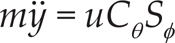
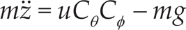


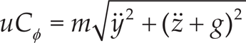
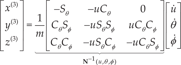
where Sθ ≡ sinθ, Cθ ≡ cosθ, Sφ ≡ sinφ, Cφ ≡ cosφ, m is the mass, g is the gravity acceleration, x and y are coordinates in the horizontal plane, z is the vertical position, the angles φ, θ and ψ express the independent orientation angles, u is defined as the total thrust, and τψ, τθ and τφ denote the angular moments (yawing moment, pitching moment and rolling moment, respectively).
After defining the system dynamics, the problem formulation studied in this work is now stated:
Given a set of smooth reference trajectories
Flatness of the System
According to the theory of differential flatness [24], a dynamic system,


and

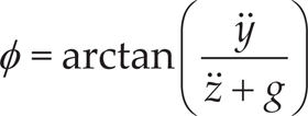
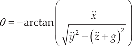
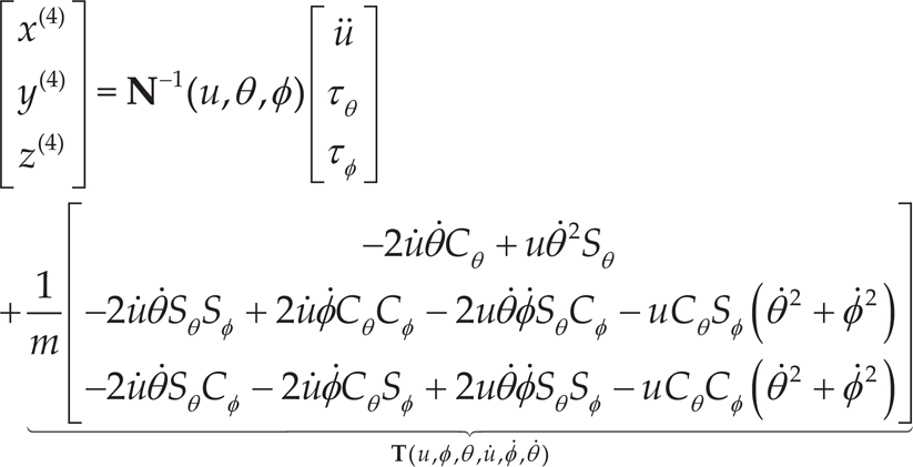
From expressions (7), (13) and (14), it can be seen that the relationship between the control input vector, (u,τφ,τθ,τψ), and the flat output's highest derivatives, is not invertible. This reveals an obstacle in the input vector to achieve static feedback linearization, and points to the need for a second-order dynamic extension of the control input u in order to exactly linearize the system (see [25] for details on the use of dynamic feedback). This yields:

Now, from expressions (2) and (3), it is obtained that
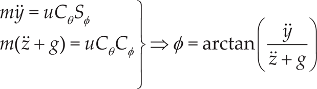
and
Then, by squaring solely expressions (2) and (3), adding the resulting terms and rearranging, yields the following result
Operating with expressions (1) and (19), we readily obtain

and

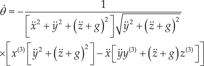
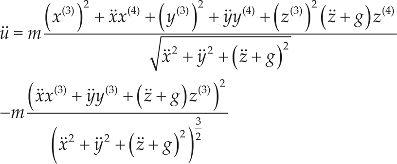
Now, if the ψ angle is differentiated twice we arrive at

On the other hand, if the expressions (1), (2) and (3) are differentiated with regard to the time and the terms are rearranged,


and, expressed in matrix notation,
or

If the expression (26) is differentiated now with regard to the time, and the terms are rearranged taking into consideration that


and, expressed in matrix notation,
or
Finally, the proof is completed after substituting (16), (18), (21) and (27) in (32). □
As was described in Section 1, GPI control consists of the defective integral reconstruction of the state which, a priori, neglects the effects of unknown initial conditions and the effect of possible classical perturbation inputs (constant and low-order time polynomial errors, such as ramps and parabolic signals). They are based on the central observation that the states of observable linear systems may be integrally parameterized in terms of inputs and outputs alone (i.e., linear combinations of inputs, outputs and of a finite number of iterated integrals of signals). The errors of integral reconstruction are to be compensated, later, by a suitable linear controller containing a sufficient number of iterated integrals of the tracking error or else of the input error [21]. The control scheme proposed for the control of the quadrotor model is illustrated in Figure 2.
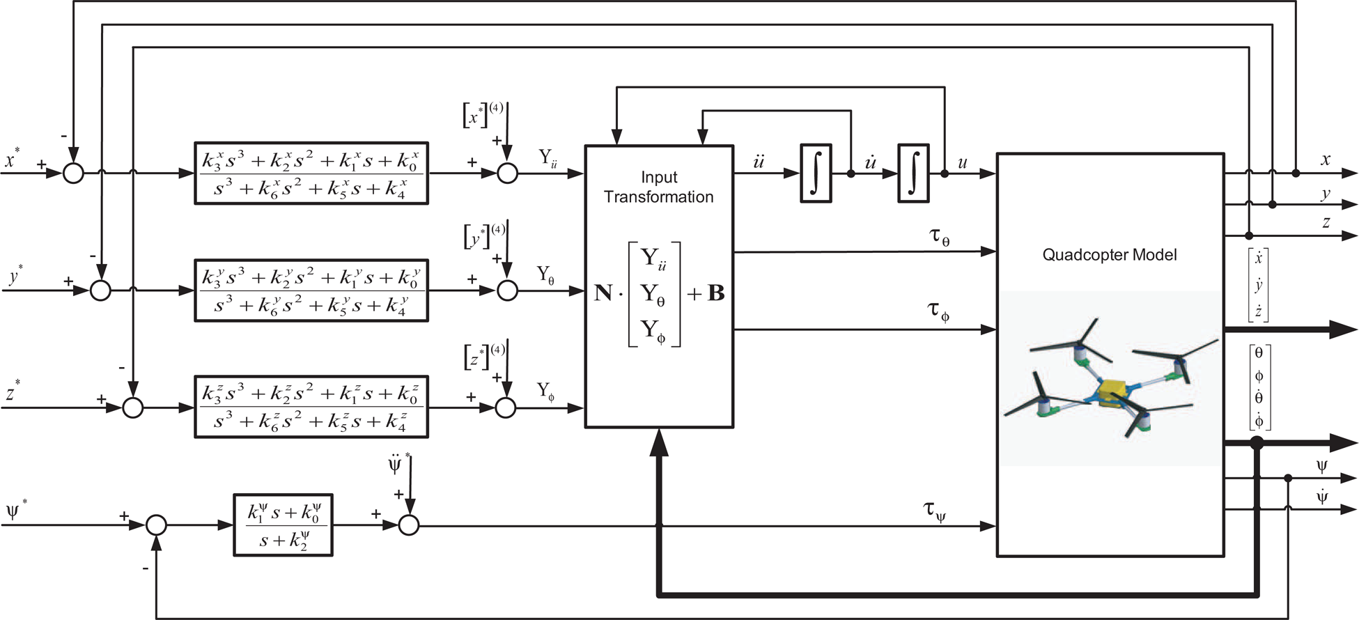
GPI control scheme
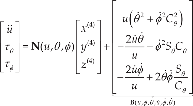
From the developments obtained in the previous section the following input-to-highest-derivative of the flat outputs' relations is achieved:

Now, if we define the virtual input vector,

and this input transformation is applied to the dynamical system (33), the whole dynamics model is now expressed as

The GPI-based flat output feedback controller is synthesized as follows: Expression (35) is a fourth-order system in which is regulated the x-position of the quadrotor model towards a given smooth reference trajectory,

Subtracting (39) from (35) yields the following:

where

In such a case, the closed-loop tracking error for the x-position variable evolves, and is governed by

The design parameters
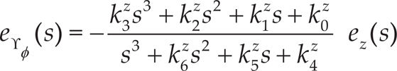
The relation between the structural estimates and the real values of the states of the system are given by


where

Substituting (43)–(45) in (49), and after some rearrangements, we achieve

After using Laplace's transform in (50), we obtain the final form for the auxiliary control input variable

On the other hand, the use of (46)–(48) on the modified controller expression (49) results from the substitution of expression (40) and differentiating on three occasions in the following seventh-order linear tracking-error dynamics:

The design coefficients

into a Hurwitz polynomial with desirable roots. Therefore, the specification of the set of design coefficients
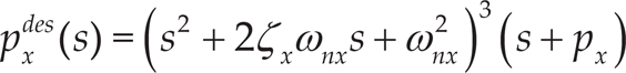
where ζx, ωnx and px are positive quantities. Therefore, the design coefficients

With a view to avoiding repetition, similar control laws are developed for the position variables y and z (given in expressions (36) and (37)). Substituting the pair

On the other hand, the dynamics given in (38) comprise a second-order system in order to control the orientation angle ψ of the quadrotor towards a given smooth reference trajectory, ψ*(t), with τψ acting as the control input. In this case, the open-loop control input
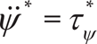
Subtracting (58) from (38 yields)

where eψ = ψ − ψ* and
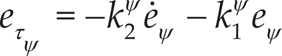
This yield, evidently, a differential equation for the output tracking error, eψ, given by
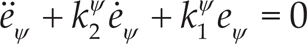
The characteristic polynomial, associated with this equation is

Thus, the design problem reduces to an appropriate choice of the feedback controller gain so as to make the above polynomial like Hurwitz's. However, the tracking controller (60) requires knowledge of the signal

When the reconstructor is used in the derivative part of the PD controller, the constant error is suitably compensated by the addition of an integral error term to reject the effect of the unknown constant initial conditions

Substituting (63) in (64), and after some rearrangement, we achieve

Following a similar procedure to that used for the variables x, y and z, and using Laplace's transform, the following result is yielded for the control input variable

Now, using (63) in the modified controller (64) results upon substitution of (59), and differentiating once with regard to time for the following third-order linear tracking-error dynamics,

the characteristic polynomial, associated with the previous equation, is easily shown to be
where the set of design coefficients
where ζψ, ωnψ and pψ are positive quantities. Identifying each term of the expression (68) with those of (69), we obtain directly the value of the set of coefficients


Next, using (34), the following result is obtained:

Finally, the section is concluded by stating the following proposition, as proved in the above developments:
where the sub-index i = x,y,z, the design coefficients of which can be chosen according to expressions (55) and (70) so as to render the origin of the tracking-error space into an exponential asymptotically equilibrium point.
Numerical simulations were carried out in order to verify the efficiency of the proposed approach in terms of the quick convergence of the tracking errors to a small neighbourhood of zero, smooth transient responses and low control effort. In the simulations, in order to evaluate the performance of the proposed controller, it is desirable to track the following sinusoidal trajectories for the variables x and y (defined as x*(t) and y*(t) respectively),

whereby R = 4[m], a = 0.0625 [rad/s7] and b = 0.1875 [rad/s]. The trajectory defined for the flat output z, defined as z*(t), is a smooth trajectory defined during a finite interval of the form [ti,tf], from an initial value

with

where the coefficients r1,…, r9 were obtained with polynomial interpolation satisfying the following restrictions:

We find that:

Finally, the trajectory for the flat output variable ψ, defined as ψ*, is designed as a linear evolution as

with c = 0.8[rad / s]
On the other hand, the sets of coefficients of the GPI controller
Two sets of simulations were developed to establish a comparison between the GPI control presented in this paper and a classical PID control. The comparison is carried out on the basis of the following aspects: (1) the stabilization process and trajectory tracking; (2) performance when the signals are noisy; and (3) responses to environmental uncertainties, such as gusty winds. These simulations will be described in detail in what follows.
In this computer simulation, the quadrotor has to track the trajectory defined by expressions (73), (75) and (78) under ideal conditions, which implies that the measured signals are not corrupted by noise and that there are no environmental uncertainties.
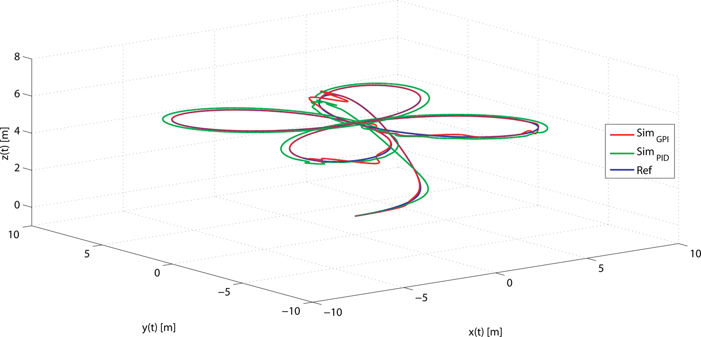
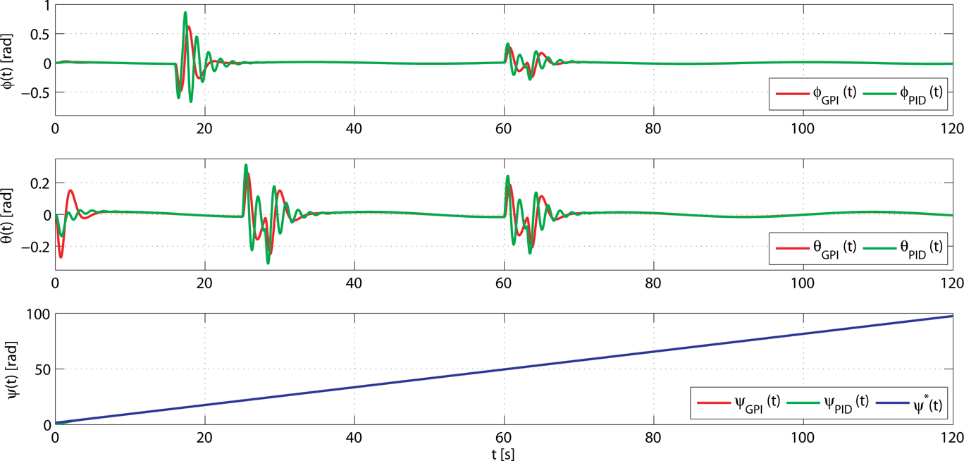
The time evolution of the closed-loop centre of mass position-variables using the GPI and the PID control is illustrated in Figure 3, and the controlled evolution of the centre of mass of the quadrotor in 3D is depicted in Figure 4. As can be observed, the tracking of the variables x, y and z of the prescribed trajectory illustrates that the GPI control drives the system towards perfect tracking of the prescribed trajectories, showing an important improvement with respect to the PID control. This fact is demonstrated in full in the tracking trajectory of the quadrotor in 3D. Additionally, the tracking for the ψ variable presents better behaviour using the GPI controller, as is observed in Figure 5. Furthermore, in Figure 5 is shown the evolution of all the closed-loop attitude variables of the quadrotor using the GPI and PID controllers. Finally, the evolution of the control input variables is displayed in Figure 6, using the GPI and the PID control, illustrating the efforts made by the feedback controllers in guiding the errors of the states towards a fairly small neighbourhood close to zero.

Position variables and reference variable of the center of mass of the quadrotor

3D centre of mass quadrotor trajectory
In this computer simulation, the measured controlled variables

Attitude variable of the quadrotor

Applied control inputs


where the selected standard deviations μn(t), for n = x,y,z, were set to be 3.17 · 10−4, and the standard deviation for μψ(t) was set to be 3.17 · 10−4. Additionally, we introduced in the simulation the atmospheric disturbances (gusty wind) shown in Figure 7 and defined as in [26]. Figure 8 depicts the controlled evolution of the position variables of the centre of mass of the quadrotor under noisy measurements and atmospheric disturbances, and Figure 9 displays the evolution of the centre of mass of the quadrotor in 3D under these new conditions. Similarly as with the previous simulations, the performance of the quadrotor using the GPI control is improved significantly in comparison to that obtained with the PID control. It is observed that, when the atmospheric disturbances affect the quadrotor, the GPI controller corrects these undesirable effects and again drives the tracking error trajectories to a small neighbourhood on the origin of the tracking-error phase space. In Figure 10 is presented the evolution of all the closed-loop attitude variables of the quadrotor using the GPI and PID controllers as well as the tracking for the variable ψ, showing again improved behaviour with respect to the PID controller. Finally, in Figure 11 is displayed the evolution of the control inputs using the GPI and the PID controllers. In this figure the high robustness of the GPI control is demonstrated in comparison with the PID control when the measured controlled signal are affected by noise.

Atmospheric disturbances used in the simulations

Position variable and reference variable of the center of mass of the quadrotor under noisy measurements and with gusts of wind
3D center of mass quadrotor trajectory under noisy measurements and with gusts of wind
Attitude variable of the quadrotor under noisy measurements and with gusts of wind

Applied control inputs noisy measurements and with gusts of wind
In this paper, the theoretical applicability of the GPI controller technique for regulation and trajectory tracking problems in a quadrotor has been investigated. The proposed scheme renders state observers and time discretizations completely unnecessary. GPI control sidesteps the need for traditional asymptotic state observers and proceeds directly to use structural state estimates in place of the actual state variables. The effect of such structural estimates in the controller are neglected in the feedback control law by means of suitable integral output tracking-error feedback control actions. Numerical simulations were provided to demonstrate the effectiveness of the proposed approach in comparison with the classical PID control in the following terms: (a) stabilization and trajectory tracking tasks; (b) performance when the measured signals are corrupted by noise; and (c) dynamic response when atmospheric disturbances, such as gusty wind, affect the quadrotor. The results show that the behaviour of the proposed approach improves the behaviour of the system in all aspects in comparison to the PID controller. Future work will be devoted to verifying the effectiveness of the proposed control algorithm through use in experiments with a real platform. This will be the topic of future publications.
Footnotes
6.
This work is partially supported by the Spanish Ministerio de Economía y Competitividad / FEDER under TIN2013-47074-C2-1-R grant.