
Abstract
In this paper a simple but effective measuring system for endoluminal procedures is presented. The device allows measuring forces during the endoluminal manipulation of tissues with a standard surgical instrument for laparoscopic procedures. The force measurement is performed by recording both the forces applied directly by the surgeon at the instrument handle and the reaction forces on the access port. The measuring system was used to measure the forces necessary for appropriate surgical manipulation of tissues during transanal endoscopic microsurgery (TEM). Ex-vivo and in-vivo measurements were performed, reported and discussed. The obtained data can be used for developing and appropriately dimensioning novel dedicated instrumentation for TEM procedures.
Keywords
1. Introduction
Rectal resection combined with total mesorectal excision represents the gold standard for the surgical treatment of mid- and low rectal cancers [1], but it is burdened by significant postoperative morbidity [2], including sexual and urinary dysfunctions [3–5], stoma-related complications, changes in body image and depression due to the presence of a stoma [6].
The development of transanal endoscopic microsurgery (TEM) has led to the evolution of the treatment of early rectal neoplasms [7, 8]. First developed in 1983 by Gerhard Buess in Tübingen, Germany, the instrumentation and procedure for transanal resection of rectal tumours remains almost unchanged [9]. The main advantage, after local excision by TEM, is to preserve the anatomical and functional integrity of the rectum to avoid the functional disorders that are common after radical surgery. While transanal local excision with retractors is associated with a high incidence of local recurrence, particularly for tumours in the proximal rectum, TEM combines the advantage of a less invasive transanal approach (low recurrence rates) with a more precise dissection due to enhanced visualization of the surgical field [10, 11]. Standard TEM instruments (e.g. Richard Wolf Medical Instruments Corp, Vernon Hills, Ill) include a 40 mm diameter operating rectoscope in 70 mm, 120 mm and 200 mm lengths, with bevelled tips. Today, the most used platform is the TEO TM (Karl Storz, Tuttlingen, Germany), which is provided in two different lengths of 75 mm and 150 mm, but with the same 40 mm diameter. The rectoscope is connected to a dedicated plate that incorporates a microscope-laparoscope aperture and a large opening with silastic seals for rigid instruments.
Robotic platforms, such as Da Vinci Surgical System (Intuitive Surgical, CA, USA, - www.intuitivesurgical.com), have been proposed for transanal procedures [12–17]; despite the possible advantages of providing greater dexterity and better ergonomics to the surgeon, such platforms are quite expensive and their true potential, in the management of rectal tumours, still needs to be verified [17].
Instruments that could allow a better manoeuvrability in confined space may considerably simplify the procedure. Flexible endoscopes, especially if combined with shape-locking overtube technology, can provide additional advantages over long and rigid instrumentation, but still present technical difficulties in instrument manipulation due to poor triangulation [15]. Robotic endoscopic platforms can be an alternative solution, introducing several advantages with respect to standard rigid instrumentation [18]. While flexibility enables the target to be reached even at a distance from the anal verge, as for traditional flexible endoscopes, these platforms may fail at providing a complete and satisfying dissection of early neoplasms larger than 20 mm [19].
In order to take advantage of both endoscopic platforms and robotic technology, robotic arms can be integrated on the tip of an endoscope as presented in [20, 21]. This strategy allows the increasing of dexterity at the surgical target while keeping the triangulation of the surgical instruments and flexibility of the endoscope in reaching the target. The integration of robotic arms on the endoscope tip introduces technical challenges, mainly regarding the distal actuation system. For example, in Phee et al. [21], a cable actuation with externally located motors is proposed. This approach may create issues in terms of bringing out the cables along the endoscope, cable friction and backlash. Embedding actuators directly on the tip can solve these kinds of problems. However, there are encumbrance issues to be considered, since the typical diameter of a standard endoscope is about 9 mm and the integration of the on-board actuated robotic arms has to cope with this space limitation. A different approach is proposed in [22], where the robotic arms are integrated in a removable cap on the tip of the endoscope.
In general, the actuation methodology, the dexterity, and the workspace of the robotic platform are the parameters that most affect the design of surgical robots. The evaluation of the involved forces during typical surgical procedures is crucial for setting the design specifications (e.g., choice of actuators, reduction stages, need for gearboxes or pulleys, and thus the overall dimensions) of new medical robotic devices, self-standing, or for integration on a standard endoscope. Force is an objective reference parameter for the design of most of the robotic platforms.
To evaluate forces in surgical tasks, a sensorized device for the measurement of forces applied during TEM is proposed in this work.
Sensorized medical tools have been developed by several research groups with the aim of evaluating grasping force, lateral and longitudinal forces and soft tissue biomechanical characteristics in in-vivo laparoscopic conditions [23, 24]. Force measuring manipulators have been proposed for in-vivo characterization of the surgical environment, in order to evaluate the instrument motion [25] or the interaction forces with tissues [26–29].
Measuring the force applied at the tip of the instrument during in-vivo minimally invasive procedures introduces some challenges due to the presence of the access port and the complexity of the integration of miniaturized force/torque sensors on the tip of the instrument itself. Such an approach asks for the development of a dedicated instrument that should fulfil the requirements for being used in an in-vivo environment. Miniature force/torque sensors using piezoresistive technology [30, 31] or fibre-optic sensing technology [32–34] have been proposed. However, distal sensors may suffer from two major issues: i) the limited robustness and ii) the difficulty to avoid coupling between the sensor and the steering mechanism for the tool at the tip and/or the local degrees of freedom of the instrument tip [29].
Bringing the sensing system to a proximal position can lead to several advantages such as fewer constraints for miniaturization, and a limited need for modifications of dedicated instruments. A single force measurement device can be compatible with several different surgical tools instead of one force sensor for each tool. However, the presence of the access port where the tool pivots may compromise the measurements due to additional friction forces; such an issue has been addressed in the literature by integrating a force sensor into the access port [18, 35, 36].
In this paper, a simple but effective external measurement system for force estimation in endoluminal procedures is presented. Such system involves the use of two force/torque sensors for measuring the forces applied by the surgeon and the reaction forces on the access port (namely the TEM rectoscope in this specific case) during TEM procedures.
1.1 Dissection Task During TEM Procedures
In order to remove rectal neoplasms using TEM, surgeons use a dedicated rectoscope fixed with a holding arm to the operating table. In Figure 1–a, a commercial TEM system is shown along with the instrumentation typically used. A 5 mm 30° optics and three rigid 5 mm instruments are introduced through dedicated ports on the front of the rectoscope [37]. One instrument is used for grasping the lesion and exposing it, and another is used for cutting the tissue with a high frequency dissector (as schematized in Figure 1–b); the third tool is used mainly for suction and aspiration procedures. The dissection is performed circumferentially around the lesion. The exposure of the tissue consists of a lifting and pulling of the tissue in order to put sufficient tension on it, which allows easier dissection. This defines the main force requirement for this type of surgery and for most dissection/excision tasks in endoluminal procedures.

a) TEM system (Richard Wolf Medical Instruments Corp, Vernon Hills, Illa).) The instruments used (graspers and monopolar knives) are passed through dedicated access ports of the rectoscope. b) Schematic representation of a typical procedure for tissue resection during TEM. Only the instruments involved in the dissection are schematized, i.e. the grasper, the monopolar knife and the optics.
Here, the authors present a compact force measurement tool compatible with TEM procedures for deriving the required forces during tissue exposure. Due to the critical physical constraint of a TEM scenario and of endocavitary districts in general, knowledge of the required forces for tissue manipulation represents a key parameter for the design and dimensioning of novel medical instrumentation for TEM interventions and other typical endoluminal procedures. The force necessary for exposing the tissue and holding it with appropriate tension was measured using a sensorized instrument that allowed the decoupling of the measurement of the forces applied for lifting the tissue from those necessary for pulling it. These two movements were considered the most relevant of those performed during tissue exposure. Ex-vivo and in-vivo measurements of forces involved during TEM were performed using the compact force measurement tool, as reported and discussed in the next sections.
2. Materials and Methods
Forces exerted by surgeons for lifting and pulling rectal tissues with the developed device were measured both ex-vivo and in-vivo. In order to replicate the same conditions experienced by surgeons, an endoscopic grasper routinely used for TEM was adapted.
2.1 Force Measurement Tool Description
The design of the force measurement system is shown in Figure 2. The system is composed of two parts: one fixed close to the surgical tool's handle and another close to the rectoscope.

Overview of the proposed force measuring system
The part close to the handle of the instrument has the function of constraining the trajectory of the surgical tool along the x or z axis and measuring the force directly applied by the surgeon to the instrument. The whole system is held by a 6-degree-of-freedom (DoFs) passively orientable arm (Martin Arm, Martin GmbH & Co, Tuttlingen, Germany) that can be fixed to the operating table. The design of this part of the system is shown on the right side of Figure 2. A 6 axis F/T sensor (NANO17, ATI, USA, resolution = 0.00625 N) is connected to the slider (yellow in the picture) that constrains the motion along the z direction by means of guiding grooves. Forces are applied by the surgeon using a rigid rod (green in the picture). The position of the slider along the z axis can be fixed at different heights by means of four screws. Translation along the x axis can be obtained by shifting the whole slider for the z axis along the x direction. All components are fabricated in Delrin® and aluminium; the sliding parts for the x axis slider are produced in Teflon to reduce friction and their motion is constrained by aligning grooves as for the z axis slider.
The motions imposed with the sliders are transmitted to the surgical tool by means of a rigid rod (shown in grey in Figure 2). The rod is simply tied to the surgical instrument with an inextensible wire. This coupling strategy allowed for easy connection between the surgical tool and the measuring system without constraining the relative reorientation between the tool and the rod.
The system can be connected to the surgical instrument in different configurations according to the space requirements of the operating room and depending on the possible interferences with other instrumentations, e.g. the vision system. In particular, the measuring system can be positioned either above or below the laparoscopic tool as done during the in-vivo tests for guaranteeing the space necessary for the camera. A different configuration - preferred by some surgeons - consisted in placing the Martin arm on top and putting the slider upside down with respect to the configuration shown in Figure 2, and thus inverting the way the z-slider in mounted. This configuration does not affect the results of the measurement since at the beginning of the procedure gravity is compensated.
The part close to the surgical TEM rectoscope (Figure 2, on the left) has the function of measuring the reaction forces on the instrument due to the fulcrum effect of the access trocar. It is composed by a tripod (not illustrated in Figure 2) used for positioning the system at the correct height with respect to the TEM rectoscope, a 6 axis F/T sensor (MINI 45, ATI, USA, resolution = 0.025 N) and a 3 DoFs joint for guiding the instrument shaft. Such joint allows translation, for inserting the instrument, and two rotations (yaw and pitch) thus replicating the effect of the TEM rectoscope itself.
2.2 Measurement Protocol
Both in the ex-vivo and the in-vivo tests, each surgeon was asked to perform an exposure of the endoluminal tissue using a 5 mm Johan endoscopic instrument (Microfrance, St Aubin, France). The procedure consisted of four different phases, in which the surgeon performed the surgical procedure acting on the system of Figure 3-a, as follows:

a) Scheme for the measurement setup. b) Corresponding involved forces; Fr. Fs, Ft can be along ±z or ±x.
Phase (1) - the surgeon inserted the sensorized laparoscopic tool through the rectoscope port, and positioned the tip of the instrument at about 80 – 120 mm from the rectoscope front plate with the instrument handle.
Phase (2) - the surgeon approached the colorectal tissue with the grasper by applying the Fs on the rod along z+ direction (Ft along z-). The tissue was then grasped from the handle and the grasper locked.
Phase (3) - The surgeon applied a force on the rod along z-direction (Ft along z+) in order to lift the endoluminal tissue until a good exposure of the tissue was obtained.
Phase (4) - The surgeon, still using the same rod mentioned above, pulled the endoluminal tissue along x+ direction (Ft along x+).
The surgeon performed each phase announcing the task he/she was going to perform (from phase 1 to phase 4). In addition, during tissue lifting and pulling phases (phase 3 and 4), the surgeon was asked to maintain the applied force for at least 1 second in order to better identify the different phases in the post processing analysis. Forces have been measured during each phase.
In particular, the surgeon was able to apply forces directly on the green rod along x and z direction by means of a slider allowing the two translations, in order to move the surgical tool accordingly. According to Figure 3–b, Fs is the force applied by the surgeon for moving the instrument and measured by the Mini 45 Load Cell. Fr is the reaction force that is measured by the Nano 17 Load Cell while Ft is the force at the tool tip that we want to estimate basing on the measured forces Fs and Fr. Fs and Ft are measured along x and z axes. During the experiments, the instrument is positioned horizontally and gravity is compensated by subtracting the offset on both F/T sensors, thus only Fr, Fs, Ft are considered.
The resulting forces applied to the tissue, Ft, can be simply computed as the difference between the force applied by the surgeon, Fs, and the reaction force measured at the fulcrum point, Fr, both in the case of the lifting and pulling measurements, as in the following equations:


2.3 In-vitro Validation of the Sensorized Device
The force measuring system was validated in in-vitro conditions by applying forces with the grasper to a mono-axial force gauge (FMI-100, Alluris, Freiburg - Germany); such a sensor has an accuracy of 0.2% that was considered satisfying for the application scenario. Forces ranging from 0 to 4 N with a step of 0.25 N were imposed at the grasper applying a force along the z direction in the same way as described in the measurement protocol, thus simulating the lifting procedure. The corresponding forces measured by the two F/T sensors (integrated in the force measuring system) were recorded and the calculated force (computed as the difference between the recorded forces) was compared with that effectively applied on the grasper and sensed by the mono-axial force gauge.
2.4 Force Measurement on ex-vivo Model
The proposed task consisted of a simulated procedure of tissue manipulation with a transanal endoscopic operation (TEO) instrument (Karl Storz GmbH, Tuttlingen, Germany), according to the standard technique described by Buess et al. [9]. We used the TEO training box, which is composed of a TEO rectoscope, 150 mm long, 40 mm in diameter, with three working channels for endoscopic instruments, and a 5 mm channel dedicated to a 30° optics. The TEO training box was equipped with fresh swine bowel (rectum section) of 300 mm in length, secured with silk threads both on the rectoscope and at its end (Figure 4a). The system was used in combination with standard laparoscopic units. Camera imaging was projected on-screen (Figure 4b), and inflation was obtained by a conventional CO2 thermo-insufflator, which was connected to the TEO instrumentation through a Luer lock to keep the pneumorectum at 8 mmHg pressure. The setup, including the force measuring tool, is shown in Figure 4b and Figure 4c.

Ex-vivo and in-vivo tests. a) Swine bowel in the TEO training box (ex-vivo tests); b) overview of the setup (ex-vivo tests); c) detail of the measurement system (ex-vivo tests). d) Force measurement system assembled in the operating room (in-vivo tests); e) overview of the setup (in-vivo tests); f) internal view of the bowel during the procedure (in-vivo tests).
During experiments, two expert surgeons in transanal endoscopic procedures were asked to perform a manipulation procedure introducing the sensorized laparoscopic tool in an explanted colonic tract and performing a combined tissue manipulation procedure. The procedure consisted of lifting and then pulling a portion of ex-vivo tissue according to the measurement protocol described above. The physicians were asked to grasp a tissue portion with the tool's grasper and then manage the sensorized tool for applying a vertical, and afterwards a horizontal, motion. Throughout the experiment, the exerted forces were measured by the installed force sensors. Descriptive statistics are reported, as well as the mean value and force ranges, for both forces. Force data from the two F/T sensors were acquired at 1 kHz. Datasets were filtered first with a moving median filter with a window of ten samples in order to remove outlier data. Secondly, a moving average filter (window of ten samples) was applied to smooth the noise in the acquisition.
2.5 Force Measurement on in-vivo Model
Ten experimental measurements were carried out on a domestic female pig (average weight 50 kg) with the force measuring system for calculating the required lifting and pulling forces for tissue manipulation in in-vivo conditions (Figure 4 d–f). The experiments were executed in an authorized laboratory, with the assistance and collaboration of a local medical team, after approval of the Local Ethical Committee. The protocol of tests and the instruments used are the same as described above.
After intravenous sedation, the sensorized tool was inserted transanally for about 100 mm in the bowel. During each trial, the forces required for lifting and then pulling the tissue were calculated, deriving the mean values and force ranges. Force data from the two F/T sensors were acquired at 1 kHz. Datasets were filtered in the same manner as for the ex-vivo tests.
3. Results
3.1 In-vitro Validation of the Sensorized Device
The results of the validation of the measurement system (Figure 5–a) are reported in Figure 5–b. The system demonstrated a maximum deviation of 2.7% in the estimation of the real force along z in the in-vitro environment. Each point, represented in Figure 5–b, corresponds to the difference between the average values of force detected along z by the two F/T sensors composing the force measuring system (1 kHz sampling frequency), averaged over five iterations for each set load step along the procedure. The global standard deviation was computed according to the uncertainty propagation rule. The maximum deviation between the repeated measures was 4.9%. The slope of the plot is 1 and the norm of residuals for the linear fitting is 0.013.
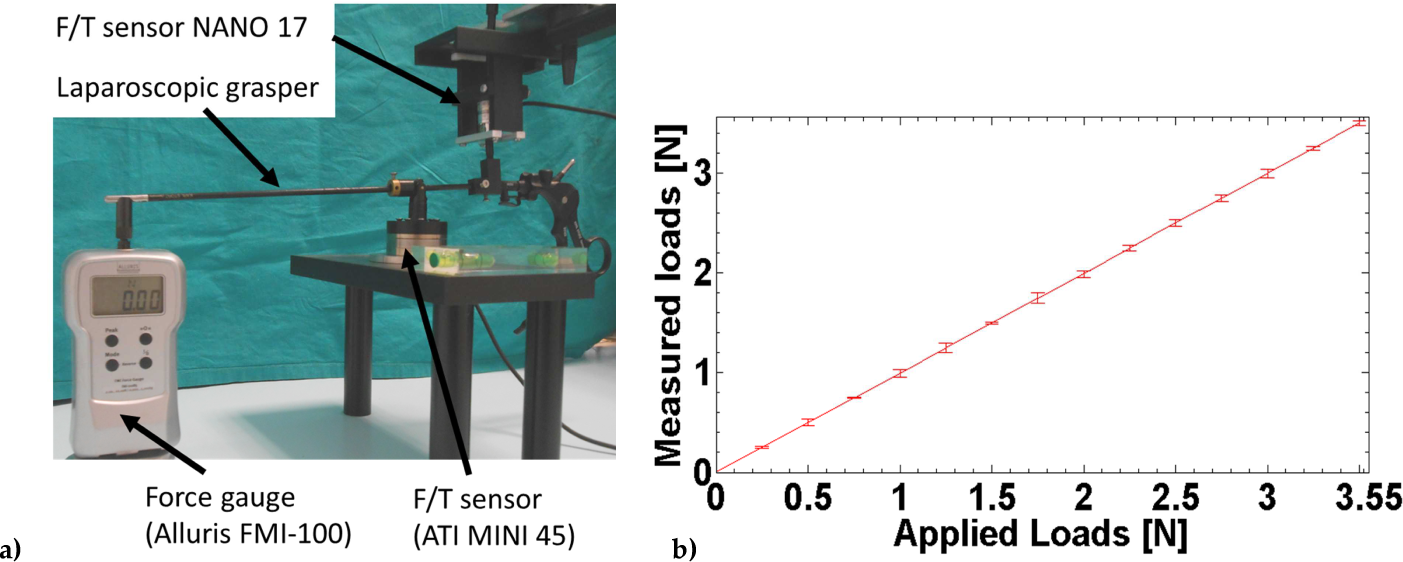
a) Setup for the validation of the force measuring system; b) results of the validation procedures: i) forces have been applied step by step with the grasper and measured by the Alluris force gauge, ii) force values have been computed as the difference between the forces recorded by the two F/T sensors (integrated in the measuring system). The graph indicates the effective correspondence (i.e., linearity) between applied and measured force values (with standard deviation).
3.2 Force Measurement on ex-vivo Model
During all the ex-vivo tests, the surgeons successfully performed the tissue manipulation for forces measurements. Lifting and pulling forces, necessary for managing the tissue for subsequent resection, resulted respectively as 1.14 ± 0.26 N and 0.93±0.30 N. The measured forces for lifting the tissue were in the range between 0.66 N and 1.53 N while the forces for pulling varied between 0.36 N up to 1.43 N. Such data were obtained by identifying the phases described in Section 2.2 on each plot and computing the average value and standard deviation of force within the specific phase during each single experiment. Then, the average force among the experiments was computed and the overall standard deviation was evaluated by combining the variability during the single experiment with variability among the experiments, according to the error propagation rule.
Figure 6-a–b shows the typical signals of the forces exerted by the physician during the ex-vivo experimental trials. In particular, the forces recorded by the two F/T sensors along the z direction and the x direction are illustrated. The blue line represents the forces directly applied by the surgeon (Fs) while the measured reaction forces (Fr) are shown in green. The different phases of the procedure are indicated in Figure 6 with corresponding numbers, within the graphs. During phase 2, the surgeon grasps the tissue. This enables easier recognition of the corresponding starts of the operating phases 2 and 3 on the acquired data. During phase 2, a force is applied for lifting the tissue that is then pulled in phase 3. It is worth noting that, when the pulling phase starts, the surgeons tend to decrease the applied force along the z direction.

Typical signals of the forces recorded during ex-vivo (a) and (b) and in-vivo (c) and (d) experiments for the phases 2 (approach, blue bar), 3 (lifting, yellow bar) and 4 (pulling, red bar) in which the surgical procedure is performed
3.3 Force Measurement on in-vivo Model
For performing in-vivo tests, the force measuring system was set up in the operating room, thus verifying the portability and compatibility with the operating room environment of the overall platform. By using the measuring tool, the operator was able to easily perform the tasks in order to derive the required force for lifting and pulling the colonic tissue, necessary for exposing the tissue sufficiently and to allow cutting using the electrocautery device. The results of the ex-vivo trials were quantitatively confirmed by the in-vivo tests. Lifting and pulling actions, necessary for managing the tissue for subsequent resection, were 0.89 ± 0.21 N and 0.58 ± 0.31 N, respectively. The measured forces necessary for lifting the tissue were in the range between 0.59 N and 1.21 N. The measured forces during the pulling procedure varied between a minimum of 0.18 N up to 1.09 N. The data processing was the same as for the ex-vivo data and results for the in-vivo experiments are shown in Figure 6-c–d. Phases are indicated and coherent with those of ex-vivo experiments.
Due to the intrinsic differences between the same curves for different users, and in order to improve readability, the typical signals of the forces exerted by the physician during the experimental trials are only shown. The lifting forces along z are reported on the top, while the pulling forces along x are shown on the bottom. As in the case of the ex-vivo force signals, in blue the forces directly applied by the surgeon are reported, while the green line represents the reaction forces measured at the TEM rectoscope. Similarly as for the ex-vivo experiment, the different phases of the procedure are indicated with the corresponding numbers, within the graphs.
4. Discussion
When introduced 30 years ago, TEM represented a major step forward in the minimally invasive treatment of rectal adenomas. This was not only the beginning of endoscopic surgery, but also of endoluminal surgery in a way that still represents the most up-to-date technique available. The increasing pressure of flexible endoscopy towards more operative procedures on the one hand, and the introduction of the concept of Natural Orifice Translumenal Endoscopic Surgery (NOTES) on the other, have pushed us to imagine novel surgical platforms to overcome current limitations.
Rigid instrumentation for TEM procedures reaches only up to 200 mm from the anus and suffers from obvious positioning constraints. On the other hand, current flexible platforms have to deal with the stability issue and with the difficulty at generating distally large forces [38]. The lack of sufficient stability and possibly also correct orientation are the most probable issues for which the use of rigid instrumentation, when possible, is still preferable. Recently, some research platforms have tried to overcome the limitations of flexible instrumentation using variable stiffness mechanisms [39–41]. In this framework, the correct definition of the forces involved during typical endosurgical procedures is important in order to appropriately design/dimension the actuation system, particularly in the case of on-board actuation where the miniaturization of actuators needs to be considered as a major constraint.
The measuring system, proposed in this paper, provides the possibility of measuring the forces required for manipulating endoluminal tissues in a TEM procedure. This work, having identified the range of forces involved, may be useful for giving initial specifications to those who will approach the design of robots for TEM and other surgical manipulation scenarios. After an in-vitro characterization of the measurement device, through extensive ex-vivo and in-vivo tests, it was possible to define the order of magnitude of forces necessary during typical TEM tasks. The analogy with other anatomical environments enables the assumption that the order of magnitude of forces defined here will also be applicable for other districts and other transluminal applications. Results for the in-vivo and ex-vivo tests are summarized in Table 1.
Summary of the forces measured in the in-vivo and ex-vivo tests

5. Conclusions and Future Works
In this paper, a system for measuring forces of tissue manipulation in TEM is presented. The sensorized device is compatible with rigid instrumentation commonly used by surgeons, and enables measurement of both the forces directly applied by the surgeon to the instrument and the forces on the TEM rectoscope or on a generic access port. This particular feature opens the possibility of using the device in in-vivo tests. Due to the simple design of the system and the direct measure of all forces involved in the procedure, no particular processing of the data is necessary. In addition, such a system could be used for measuring forces necessary in most trocar-based abdominal surgeries.
In both ex-vivo and in-vivo tests, forces less than 1.5 N were measured as necessary for the complete manipulation of endoluminal tissues. The obtained data can provide the required specifications for the development and integration of dedicated robotic tools on flexible platforms for NOTES and, most specifically, for endoluminal digestive surgery.
Footnotes
6. Acknowledgements
This work was supported by the STIFF-FLOP project grant from the European Communities Seventh Framework Programme under grant agreement 287728.