
Abstract
The variable stiffness actuator (VSA) is an open research field. This paper introduces the conceptual design and analysis of four types of novel variable stiffness actuators (VSAs). The main novelty of this paper is focused on the convenience control of the torque and stiffness of the actuator. We do not need to design complicated control strategies to achieve the desired actuating torque and output stiffness. This feature is beneficial for real-time control. In order to achieve this advantage, three types of approximate quadratic springs and four types of stiffness regulation mechanisms are presented. For the first VSA, the relationship between the output stiffness and angular deflection is close to linear, and the fitted quadratic spring is easy to implement and compact. For the second VSA, the output stiffness is only related to the working radius, and the relationship between the exerted torque and angular deflection is linear. For the third VSA, two equivalent quadratic torsion springs are used. Compared with the existing quadratic torsion springs, the design method is simple and the structure size is compact. The stiffness and torque is a linear function of the kinematic parameters of the VSA. The novelty of the fourth VSA is the use of the tension spring set. The approximate quadratic tension spring is compact and easy to implement. The relationship between the output stiffness and the angular deflection is fairly linear. The conceptual layouts and working principles are elaborated for the four actuators. The characteristics of torque and stiffness of the VSAs are presented, and the mechanical solutions are illustrated.
Keywords
1. Introduction
In recent years, interest in compliant actuation systems has grown due to a change of trends in robotic applications. Since classical stiff actuators lack adaptability, energy efficiency and interaction safety, compliant actuators are strongly recommended when robots coexist with human beings or physically interact with them [1, 2]. Among the compliant actuators, the requirement of mechanically variable stiffness joints is fulfilled by a new generation of actuators called VSAs. The VSA is characterized by the ability for the output stiffness to be varied independently from its position. The intrinsic compliance of the VSA can ensure the safety of human-robot or robot-environment interaction, even for unexpected collisions. The optimal criteria of the VSA are elaborated as follows: (1) Stiffness should be changed without energy consumption. (2) Energy efficiency of stiffness adjustment should be 100%. (3) No energy should be required to maintain the stiffness. (4) Stiffness should be independent from the external load. (5) Range of stiffness should be unlimited. (6) No inertia should be added to the output link due to the stiffness adjustment mechanism. (7) Maximum capacity of the energy storage should be accessible [3, 4].
In order to achieve the features described above, many research efforts have been put into the development of the VSA. Some designs rely on changing the transmission ratio between the output and the internal elastic elements. The AwAS-II [5], CompAct-VSA [6], CompAct-ARS [7], HDAU [8], the vsaUT [9], the vsaUT-II [10], and the mVSA-UT [11] use a lever arm of variable effective length to regulate the transmission ratio. As is elaborated in [12], the output stiffness of these variable stiffness actuators can be changed without any energy injection into or extraction from the internal elastic elements. This implies that all the energy supplied by the internal actuated degrees of freedom can be used to do work on the output without being stored in the internal springs. This is an energy efficient way to regulate the output stiffness, especially in mobile applications. However, from a control perspective, the nonlinear relationship between torque and angular deflection or stiffness and angular deflection leads to difficulties in applications. Besides, the output stiffness is often related to the exerted torque or angular deflection. To address this problem, significant research has been carried out on the control of these actuators. The complicated control strategies may be used for achieving the desired output stiffness, since the stiffness characteristic is intrinsically nonlinear. The online stiffness estimation method is proposed, since there are no sensors available for a direct measurement of the varying stiffness online [13]. The time delay caused by the complicated control strategy is not beneficial for real-time control. Real time, and the convenience of the control method, is also important for the VSA.
Compared to the actuators mentioned above, other designs are based on changing the pretension of the internal elastic elements, e.g., MACCEPA 2.0 [14], VSA-II [15], QA-Joint [16], DLR-FSJ [17], and the VSA-HD [18]. A characteristic of these systems is that the energy is put into or extracted from the elastic elements during stiffness changes. According to the functional concept and layout, they can be classified into antagonistic configurations or serial configurations. In antagonistic configurations, two elastic elements act in opposite directions at the joint, and the equilibrium position and output stiffness of the joint are controlled by two motors. In series setups, one motor is used to change the position and the second motor is used to change the stiffness by setting the pretension of an elastic element. Although the pretension of the internal elastic elements has a negative influence on the power-flow ratio of the actuators, and the nonlinear characteristics of the actuating torque and output stiffness require an advanced and complicated control strategy, these actuators are still widely used for different application requirements.
In this paper, four types of variable stiffness actuators based on spring pretension are presented. Different from the most existing VSAs, the novelty of the proposed VSAs is that the proposed internal elastic elements and stiffness adjustment mechanisms are convenient for controlling the actuating torque and output stiffness. Therefore, the control algorithms for torque and stiffness are relatively simple. The real time and convenience of the stiffness control is beneficial for improving the efficiency of task execution. In order to achieve this feature, four different stiffness adjustment mechanisms and three different approximate quadratic elastic elements were designed for satisfying the kinematic structure requirements.
The common characteristics of the four types of VSAs are described as follows. 1) The output stiffness can be changed independently of output position. 2) By using the screwnut mechanism or worm and worm wheel mechanism, energy is not required to maintain the stiffness. 3) By limiting the deformation of the spring, the output stiffness of the VSA can be regulated to infinite. This situation is necessary in cases where compliance is not desired. 4) The stiffness regulation is based on the principle of the spring pretension. 5) The error of torque and stiffness between the prescribed and actual achieved is small. Therefore, the proposed approximate quadratic springs are used to replace the desired purely quadratic spring.
This paper is organized as follows. Section 2 introduces the working principles of the proposed approximate quadratic springs. Section 3 describes the conceptual design and analysis of the first VSA. In this section, the conceptual layout and working principles of the VSA are presented and the characteristics of the actuating torque and output stiffness are illustrated. The mechanical solution of the VSA is described. Section 4 illustrates the conceptual design and analysis of the second VSA. Section 5 presents the conceptual design and analysis of the third VSA. Subsequently, the conceptual design and analysis of the fourth VSA is given in section 6. Finally, conclusions and future works are discussed in section 7.
2. Working principles of the approximate quadratic springs
Based on the mechanical solutions, for the first VSA, the relationship between the output stiffness and the angular deflection is linear for quadratic spring configuration. For the third VSA, the linear relationship between the exerted torque and the angular deflection can be achieved for quadratic torsion spring configuration. For the fourth VSA, the relationship between the output stiffness and the angular deflection is linear for the quadratic tension spring configuration. Therefore, for the convenience of control, the quadratic springs in these VSAs are essential. However, the reliable manufacturing of the quadratic spring is difficult, and the commercial availability of a purely quadratic spring is extremely limited. The quadratic spring constructed by the linear springs and a nonlinear transmission mechanism (i.e., cable, cam or curved surface, etc.) often has a relatively large size and weight, which ultimately limits their implementation in multi-DOF robotic systems [19, 20, 21]. Moreover, the special frame or cams may require relatively complicated design and manufacturing. In order to realize the quadratic spring from a linear spring and reduce the difficulty in the design, three novel types of approximate quadratic springs are proposed and demonstrated.
2.1 Conceptual design of the fitted quadratic spring
The first type of approximate quadratic spring is the compression spring set in parallel type. Since springs with different parameters can be used to constitute a spring set with arbitrary stiffness, the linear compression spring is used with different parameters to constitute an approximate quadratic compression spring.
In the design, the end portion of the spring is flat. The number of the supporting coil is one. The compression spring material is piano wire, and D grade. The parameter definitions in Table 1 are described as follows: D represents the middle diameter of the spring, d is the diameter of spring wire, k represents the stiffness of the compression spring, t is the pitch between two adjacent active coils, n is the number of active coils of the spring, and H0 is the free length of the spring. The main design criteria of the compression spring can be seen in [22]. The parameters for the compression spring set were designed and presented in Table 1.
Specifications of the compression spring set

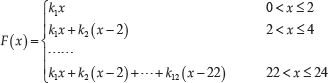
As shown in Figure 1, the number of the compression spring is 12. A different initial height for each spring inside the spring set pedestal (2) is pre-set. The working distance between the two adjacent springs is Δx=2mm. The maximum amount of deformation of the spring set is xmax=24mm. When both sides of the spring pedestal guide sleeves (1) contact with each other, the springs could not be compressed. In order to reduce the friction between the spring set pedestal (2) and the guide groove (3), and to ensure the spring set pedestal can withstand a relatively uniform pressure, the arrangement of the springs in the spring set pedestal should be optimized, as shown in Figure 1. The relationship between force F(x) (N) and displacement x (mm) of the spring set is formulated in Equation (1). By using the least squares method, the equation for the fitted quadratic spring F1(x) and the simplified equation F2(x) are formulated in Equation (2).

Schematic of the fitted quadratic compression spring

The differences of force and stiffness between the desired purely quadratic spring and the piecewise linear spring set are shown in Figure 2. The actual stiffness curve of the compression spring set is discontinuous line segments. Since the difference is relatively small, the fitted quadratic compression spring can be used in the VSA.

Characteristic of the fitted quadratic spring
2.2 Conceptual design of the approximate quadratic torsion spring
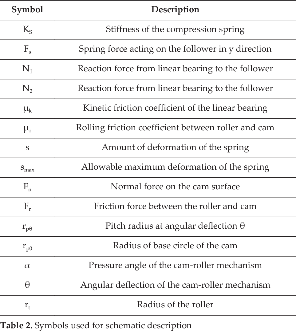
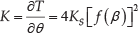
The calculation scheme of the quadratic torsion spring is shown in Figure 3, and the parameter definitions are presented in Table 2. The cam is being deflected by an angle θ due to the applied actuating torque τ(θ). The follower is being pushed up by the force Fn, and the spring is compressed in the y direction. The amount of deformation of the spring depends on the pitch radius of the pitch profile. The force at the equilibrium state of the follower is obtained such as:


Mechanism schematic of the quadratic torsion spring
Symbols used for schematic description
In the mechanical solution, the rolling bearing and the linear bearing are used in the follower. The friction force can be neglected in the calculation due to the relative small friction coefficients. To simplify the calculation, the inertia of the moving bodies is not considered, and the mass of the spring is considered null. The characteristics of actuating torque and output stiffness of the equivalent quadratic torsion spring can be expressed as follows:

The characteristic of a purely quadratic torsion spring is defined by τ(θ)=aθ2. From the principle of virtual work:

where s is the amount of deformation of the spring with respect to its natural length. The number of the springs compressed during the rotation of the cam is defined as λ. It is noted that the profile of the cam is not affected by the number of compression springs. Suppose that τ(θ)>0 and s>0. The expression of and α is formulated such as:

where s0 is the displacement of the spring when θ=0, and s0 =0. In the calculation of τ(θ), the units of KS, smax, θmax, and θ are N/m, m, rad, and rad, respectively. In order to more clearly express the profile of the cam, in the calculation of the s, the units of KS, smax, θ max , and θ are N/mm, mm, rad, and rad, respectively. Therefore, the unit of s is mm. As is described in Figure 3 (b), the profile of the cam can be determined by considering the motion of the follower relative to the cam profile's frame of reference (i.e., by assuming the cam as fixed). At the initial position, the tangency point of the roller on the cam profile is denoted with B0. When the follower is rotated by an angle θ in the CCW direction around the cam, the tangent point is shifted from point B0 to point B1. Let the coordinates of the tangency point B1 be X and Y, and the coordinates of the A1 is denoted by x and y. Finally, the profile of the cam can be expressed as follows:
Two types of mechanical solutions for the quadratic torsion spring are designed. The first type of equivalent torsion spring consists of two compression springs. The spring parameters are defined as: H0=32mm, d=2.5mm, D=14mm, n=5, KS=28.13N/mm. Suppose that θ=0.5πrad corresponds to s=12.5mm. The maximum amount of deformation of the spring is 12mm by the mechanical limit, and the maximum allowable angular deflection is ±1.527rad. The cam parameters are defined as: rt=6mm, rp0=22mm, α max =19.1°, λ=2, and a=3.402. The second quadratic torsion spring consists of four springs. The spring parameters are defined as: H0=26mm, d=1.6mm, D=14mm, n=4, and KS=5.9N/mm. The maximum amount of deformation of the spring is 12mm by the mechanical limit. Suppose that θ=0.25πrad corresponds to s=13mm. The cam parameters are defined as: rt=6mm, rp0=25mm, α max =33.1°, λ=4, and a=12.35. The maximum allowable angular deflection is ±0.7454rad. The profiles of the cams and the curves of pressure angles are shown in Figure 4.

Cam profiles and pressure angle curves
The mechanical solutions for the two types of equivalent torsion springs are shown in Figure 5. Each compression spring is equipped with two linear bearings (4) and two guide shafts (1). The spring is placed in the pedestal (2), and the cam (3) is used to drive the roller. The pressure angle is an important parameter for evaluating the friction dissipation, and the range of angular deflection is an important measure of compliance. In the design of the third VSA, the first type of equivalent quadratic torsion spring will preferably be used as the elastic unit.

CAD assembly of the quadratic torsion spring
2.3 Conceptual design of the approximate quadratic tension spring
The third type of approximate quadratic spring, which is constituted by a tension spring set with a triangular structure, is illustrated in Figure 6. Compared with the existing quadratic spring based on a curved surface, cam or a varying-radius shaft, this method is easily implemented and the structure is compact. The design of the quadratic spring can be achieved by optimizing the design parameters to minimize the error between the prescribed and achieved load-displacement function.
Schematic description of the second quadratic spring
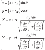
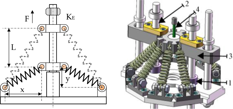
Suppose that the approximate quadratic spring element constitutes eight of the same tension springs. The bulge (1) is used for spring initial pretension. The guide rod (2) and the pedestal (3) are connected by the linear bearing, so the friction is neglected in the calculation. The stiffness of the cable (4) is considered infinite (no stretching). The x and y represent the initial position of the spring on the frame. The spring constant is Ks, the amount of deformation of the spring along the direction of the force F is L, and the equivalent stiffness of the spring set along the direction of the force F is KE. The KE can be calculated as follows:

To achieve a prescribed load-displacement function (i.e., the purely quadratic spring F(L)= aL2), the error function ΔF and ΔK are defined as:

By optimizing the design parameters (i.e., x, y, Ks and allowable amount of deformation L) of the spring element, the error is small. Finally, the parameters are obtained as: x=33mm, y =5mm, Ks=1.5N/mm, and L is defined from 0 to 24mm. The prescribed load-displacement function is F(L)=0.1452L2. The differences between the desired purely quadratic spring and actual approximate quadratic spring are shown in Figure 7. The differences are relatively small. Therefore, the characteristics of the torque and stiffness of the proposed fourth VSA can be calculated by using the tension spring set, and the high level of linearity of the output stiffness-angular deflection curve can be achieved.

Comparison of the desired quadratic spring and the approximate quadratic tension spring set
3. Conceptual design and analysis of the first VSA
3.1 Conceptual layout of the first VSA
The actuator discussed in this section is based on the use of the tendon tensioning mechanism and spring preload mechanism. A simple schematic is shown in Figure 8. The output disc (1) and the driving pulley (2) are coaxially connected by bearing. The stiffness regulation mechanism components are located in (1). The two ends of the tendon are connected with the spring pedestal (8) and the pulley (2), respectively. The tendons (3) and (4) are used for counter clockwise rotations while the (5) and (6) are used for clockwise rotations. The two pairs of tendons are in different planes to avoid crossing. The radius of the (2) is RJ. The initial distance of the two spring guide sleeves is S. When the two-spring guide sleeves contact with each other, the springs cannot be compressed any further, and the actuator will switch into the stiff operation mode from the compliance mode. The movable pulley rod (10) and the movable baffle (7) are used for spring pretension, and to ensure that the tendons will not become slack when the springs are compressed. As is shown in Figure 8(b) andFigure 8(c), the (2) is rotated at an angle β with respect to the (1) under the action of the applied external torque text. The amount of deformation of the spring is Δh. Because the relationship between the displacement amount × of the (10) and the displacement amount ΔL of the (7) is nonlinear, the screw transmission mechanism and roller-cam mechanism with self-locking function are proposed.
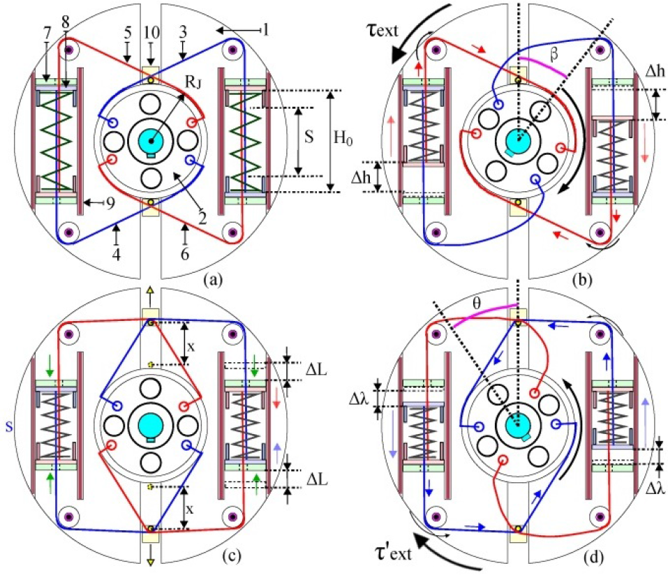
Conceptual principle of the first VSA: (a) Initial state. (b) Rotate an angle β under the applied external torque. (c) Stiffness control (d) Rotate an angle θ after stiffness adjustment
3.2 Mathematical modelling of the first VSA
As is illustrated in Figure 8(d), under the applied external torque τ′ ext , the angular deflection between the (2) and the (1) is θ. The actuating torque TE and output stiffness K at the elastic transmission for the linear spring configuration are formulated as follows. The linear spring constant is KS.

In addition, the calculation formulas of the torque TE′ and stiffness K′ for quadratic spring configuration (i.e., F(x) = ax2) are shown as follows:

As is illustrated in Figure 8(c), the movable pulley rod (10) and the movable baffle (7) are used to ensure that the tendons always maintain contact with the driving pulley. The related design and kinematic relationship are shown in Figure 9.

Schematic description of the stiffness adjustment mechanism
Figure 9 shows the relationship between the × and the ΔL. Suppose that the movable pulley rod is moved from initial position point O to point O′. Since the radius of the fixed pulley is small, the contact point A is considered to remain unchanged. The radius of the movable pulley rod is considered to be null. The angle α, |AO|, |CO|, |DO|, and the tendon length from point A to point B are known. The related calculation can be expressed as follows:
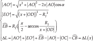
The pedestal (1) of the movable pulley rod is driven by a threaded shaft (2). The number of teeth of the bevel gear fixed with the (2) is Z2 and the pitch of the threaded shaft (2) is P1. The cam (3), the spur gear (4), the rack (5), the threaded shaft (6), the movable baffle, the roller mounted on the baffle, and the bevel gear pair constitute the spring preload mechanism. The (3) is fixed with the cam (4). The number of teeth of the bevel gear fixed with the (6) is Z3 and the pitch of the threaded shaft (2) is P2. RC is the radius of the pitch circle of (4). A Cartesian coordinate system is established and the centre of rotation of the cam is the origin. The positive axis of xc is defined as the direction of motion of the movable baffle for rising travel. The angle of rotation of the (3) is β C , which corresponds to the amount of displacement x of the (1). In the cam-roller mechanism, suppose that the eccentricity is zero, the radius of the base circle is rb, and the radius of the roller is rt. Finally, the equation describing the profile of the cam for spring pretension can be expressed as:
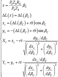
where the (xc, yc) represents the theoretical profile of the cam, and the actual profile is represented by (XC, YC). The radius of the base circle and the radius of the roller are defined as rb=8mm and rt=3mm, respectively.
3.3 Characteristics of torque and stiffness of the first VSA
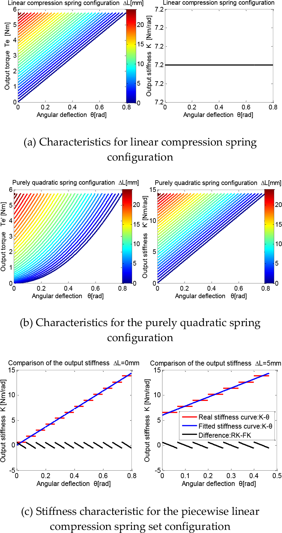
In the design of the mechanical solution, the radius RJ of the driving pulley is defined as 30mm. For the linear spring configuration, the compression spring stiffness is 4N/mm. The maximum amount of deformation of the spring is 24mm and the maximum angular deflection θ is ±0.8rad. The maximum elastic output torque is 5.76Nm. The linear relationship between the stiffness K and angular deflection θ can be achieved for the purely quadratic spring (i.e., F(x)=0.1661x2) configuration. Figure 10 shows the characteristics of actuating torque and output stiffness for the different types of spring configurations (linear, quadratic and piecewise linear compression spring set). As illustrated in Figure 10(c), the output stiffness-angular deflection curve corresponding to the piecewise linear spring set is in discontinuous straight-line segments. The differences between the desired and achieved stiffness are relatively small.
Characteristics of torque and stiffness of the first VSA for different types of spring configurations
3.4 Mechanical structure solution of the first VSA
The mechanical structure solution is shown in Figure 11. This model is essentially composed of an output disc (2) functioning as the frame, where the stiffness adjustment mechanism components are located. The output disc (2) is fixedly connected with the rotatable housing (10) through the screws. The (10) is connected with the fixed housing (9) by the bearing (8). The motor (4) is fixedly connected with the (10) through the bracket (5) and screws. The bevel gear (3) is driven by the motor (4). The driving pulley (1) and the (2) are coaxially connected by the bearing. The motor (6) is fixedly connected with the (9) by the bracket (7) and screws. The motor (6) is used to drive the (1) and control the output position. To reduce the vibration of the springs, the gap between the guide sleeve and the outer race of the spring is small. The allowable range of rotation of the stiffness motor with respect to the fixed housing is limited by the cables attached to it. The allowable angle range of rotation of the first VSA is defined as ±150°.

CAD assembly of the first actuator
4. Conceptual design and analysis of the second VSA
4.1 Conceptual layout of the second VSA
In this section, a VSA based on an adjustable moment arm mechanism is presented. This is an equivalent model of the lever arm mechanism. This VSA is characterized by the property that the proportion of the two moment arms can be changed, and this feature is implemented by the connecting rod and slider mechanism with self-locking function. In this design, the output stiffness of the VSA is only related to the effective working radius for linear compression spring configuration, but not to the exerted torque or angular deflection. Moreover, the relationship between the actuating torque and angular deflection is linear. This feature makes the torque control and stiffness regulation more convenient. The working principle of the second VSA is demonstrated in Figure 12.

Conceptual diagram of the second VSA: (a) Initial state. (b) Rotate an angle θ under the action of actuating torque. (c) Control of working radius of the driving disc. (d) Rotate the same angle θ after changing the radius.
The output disc (1) and the driving disc (3) are coaxially connected by the bearing (2). The motor used for regulating the compliance is mounted on the (3) and drives the screw shaft (4) and the nut (5). The (5) is connected with the (3) by the vertical guide rod. One end of the connecting rod is connected to the (5) by a rotatable pin and another end is connected with the slider. The sliders can be moved along the horizontal guide rod (6). The outer contours of the sliders form an approximate circular shape. There are four linear compression springs used in the elastic elements. Two ends of the cable are connected to each of the spring and the slider. H0 is the resting (no-load) length of the spring, ΔH is the initial amount of deformation of the spring, and the maximum amount of deformation of the spring corresponding to the initial working radius R0 is ΔLmax. To avoid cable slack, we define this relationship, i.e., ΔLmax < ΔH When the working radius of the (3) is changed from R0 to R, the additional amount of deformation of the spring is Δx, and the allowable maximum amount of deformation of the spring is changed from ΔLmax to ΔL′max. The relationship between the incremental working radius ΔR (i.e., |R–R0|) and the incremental amount of deformation of the spring (i.e., Δx) is nonlinear. When the springs could not be compressed because of the mechanical stop or the effective working radius reached the maximum allowable value, the VSA would move into the stiff mode from the compliance mode.
4.2 Mathematical modelling of the second VSA
As is shown in Figure 12(d), when the external torque τ′ ext is applied to the output disc (1), the elastic torque TE and the output stiffness K can be described by:

where F1 and F2, respectively, represent the force generated by the elastic deformation of the springs, and KS is the spring constant. The output stiffness K depends on the working radius R. The relationship between the ΔR and the Δx is demonstrated in Figure 13.

Relationship description between the ΔR and the Δx
Given that there are 20 sliders in the mechanical solution, an ideal circular is used to replace the actual approximate circular contour in the calculation. Suppose that the radius of the diverting pulley is Rs, the centre of rotation of the diverting pulley is point O′, and the centre of rotation of the VSA is point O. When the radius is changed from R0 to R, the tangent point between the cable and the diverting pulley is changed from point I to point C. The point D and the point B are the tangent points corresponding to working radius R0 and R, respectively. In addition, the radius of the cable is considered null, and the |OW| and |WO′| are known in the mechanical solution. The related calculations are formulated as:

where LNH is the length of the cable from point N to point H. When the working radius is changed from R0 to R, the length of the cable from point N to point A can be obtained by:

Finally, the relationship between Δx and R is given by:

As mentioned above, one end of the cable is connected with the slider, and the connecting point withstands the tension force from the external torque, so a ball screw mechanism with a self-locking function is designed for changing the radius. The related design is shown in Figure 14. In the mechanical solution, the stiffness motor (the one which tunes the output stiffness) is attached to the driving pulley and can change the position of the nut (1) by driving the threaded shaft (2), and the working radius is changed under the action of the connecting rod (3). Suppose that the output angle of the stiffness motor is β and the ratio of the reducer is η. The pitch of the nut (1) is PVR and the displacement is LVR. The length of the connecting rod (3) is |ab| = |a′b′|. The a, b, c, a, b′, and c are defined in Figure 14.

Kinematic diagram of the variable radius mechanism
The relationship between the angle β and the effective working radius R is given by:

where the radius R is a function of angular displacement of the stiffness motor. By substituting Equation (16) and (17) in (14), the output stiffness K for linear spring configuration is obtained by:
4.3 Characteristics of torque and stiffness of the second VSA
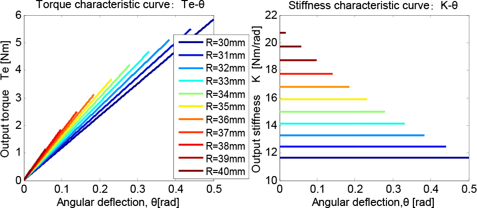
In this section, the characteristics of actuating torque and the output stiffness of the actuation system are analysed. The variation range of the effective working radius is defined from 30mm to 40.5mm. The number of the sliders is 20. The spring constant is 3.24N/mm, and the maximum amount of deformation of the spring is defined as 32mm by mechanical limit. The initial amount of deformation of the spring is 17mm. The allowable maximum angular deflection will decrease with the increase in working radius, and the maximum allowable angular deflection between the driving disc and output link is ±0.5rad. When the working radius R has reached 40.5 mm, the spring cannot be compressed, no angular deviation is mechanically allowed, and the actuator will go into the stiff operation mode.
When R0 =30mm, |WO′| =46mm, |OW| =39mm, RS =3mm, ab=a′b′=20mm, cd=19.7mm, the characteristics of torque and output stiffness of the VSA are shown in Figure 15. The mechanically allowable torque range at the elastic transmission mode is from 0Nm to 5.83Nm, and the maximum elastic torque will change with the changes of the working radius R. The mechanically allowable range of stiffness at the elastic transmission of the VSA is from 11.66Nm/rad to 20.73Nm/rad. The output stiffness K is kept constant in the allowable angular deflection range if the working radius R is unchanged. Compared with the other actuators, the control method of stiffness is very convenient even in the presence of the disturbances. This feature is beneficial for real-time regulation of the output stiffness. Therefore, we do not need a complicated control strategy to achieve the desired stiffness, and only need to change the effective working radius R.
Characteristics of torque and stiffness of the second VSA
4.4 Mechanical structure solution of the second VSA
The mechanical solution of the second VSA for linear compression spring configuration is shown in Figure 16.

CAD assembly of the second actuator
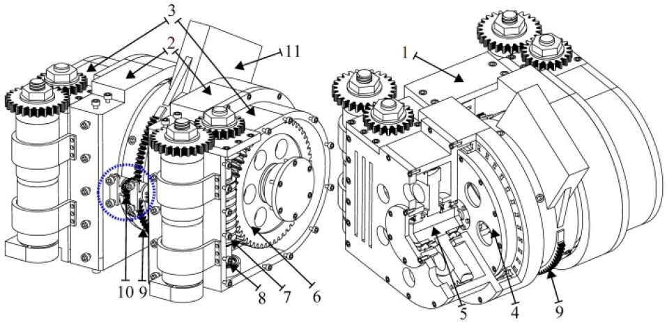
The conceptual model is essentially composed of the driving disc (3) functioning as the frame, where the variable stiffness mechanism components are located. This rotary actuator consists of the motor (13) devoted to set the output position and the motor (16) used to tune the output stiffness. The (13) is connected to the reducer. The output of the reducer is then connected to the torque sensor (14) and the spur gear. The motion of the rotatable housing (4) is realized by engaging the internal ring gear (15) and the spur gear. The (15) and the (3) are fixedly connected with the (4) through the screws. The rotatable spring pedestal (6) is connected with the (4) by the bearing (5) and fixedly connected to the output housing (9) by the set screws. The (9) is connected with the fixed housing (12) by the bearing (10) and (11). The internal ring gear (17) mounted on the (12) is engaged with another small spur gear (18) mounted on the (9). The spur gear (18) is connected with the angular deflection encoder, and the angular deflection θ can be obtained. In the stiffness regulation mechanism, the motor (16) is mounted on the (3) by the bracket. The output of the reducer of the (16) is connected to the ball screw shaft (1). The rotation of the nut (2) is restricted by the connecting rod and slider mechanism. A mechanical stop in the spring guide sleeve (7) constrains the amount of deformation of the spring. When the working radius R has reached the maximum allowable value, the VSA is completely rigid. The allowable angle range of the stiffness motor with respect to the fixed housing is limited by the cable attached to it. The allowable range of the rotation angle of the VSA is defined as ±150°.
5. Conceptual design and analysis of the third VSA
5.1 Conceptual layout of the third VSA
The third actuator is antagonistically actuated by two quadratic torsion springs. Antagonistic actuation of two quadratic torsion springs mathematically guarantees perfectly linear behaviour with adjustable stiffness. To illustrate this point, consider a quadratic torsion spring, which can rotate about point O. The characteristics of the quadratic torsion spring are defined by G(θ)=aθ2. In Figure 17(b), a mirror image pair of these mechanisms is used together. They are rotated by an angle φ and attached to each other as shown in Figure 17(c). It is noted that the equilibrium positions of the assembled joint do not change with φ. As shown in Figure 16(d), when the exerted torque M(β) is applied at the assembled joint, the joint is rotated by an angle of β. As is shown in Equation (20), the applied torque M(β) is a linear function of β and the corresponding stiffness is a linear function of φ. In this mechanical schematic, the allowable operating region of the assembled joint is defined as β∈{−φ≤θ≤φ}.

Antagonistic set-up of two quadratic torsion springs for an adjustable stiffness joint mechanism

5.2 Characteristics of torque and stiffness of the third VSA
As is shown in Figure 18, in the design of mechanical solution, the maximum allowable angular deflection β is defined as ±0.7rad, and the initial angle of rotation of the two quadratic torsion springs are −0.827rad and +0.827rad, respectively. The mechanically allowable torque range at the elastic transmission of the VSA is from 0Nm to 7.878Nm, and the maximum elastic torque M(β) will reduce with the increase of the initial rotation angle φ. The mechanically allowable stiffness range at the elastic transmission is from 11.25 Nm/rad to 20.78 Nm/rad.

Characteristics of torque and stiffness of the third VSA
5.3 Mechanical structure solution of the third VSA
The mechanical solution for the antagonistically actuated VSA is shown in Figure 19. The equivalent torsion spring for two compression spring configurations is used. Two DC motors are used to change the position and stiffness. Changing the position is done by corotation of the two motors while counter rotation of two motors is used to regulate the stiffness. The base frame (1) is used to connect the two frames (2) by the screws. The equivalent torsion spring (4) is housed in the frame (2) by a radial ball bearing. Frame (2) and frame (3) are fixedly connected by screws. The worm (7) and worm wheel (6) are housed in the frame (3) by four angular contact ball bearings (8). The output shaft (5) is driven by the worm wheel (6) and fixedly connected with the input shaft of the equivalent torsion spring (4). The output link (11) is fixed with the housings of the two torsion spring by screws. The ring gear (9) is fixed with the housing of the output link (11). The small spur gear (10) is mounted on the base (1) by the brackets and screws. The rotation shaft of the (10) is connected to a small rotary encoder. The (10) is meshed with the (9) and the angular deflection of the VSA can be obtained by calculation. Since the worm and worm wheel mechanism is used, no energy is required to maintain the output stiffness of the VSA. Due to the mechanical limit, the allowable rotation angle range of the VSA is defined as ±100°.
CAD assembly of the third VSA
6. Conceptual design and analysis of the fourth VSA
6.1 Conceptual layout of the fourth VSA
In this section, the proposed mechanism comprises a serial configuration, with the main motor determining the equilibrium position of the output link and a secondary motor to modify the output stiffness of the VSA. The tension spring set with a triangular structure is used in this design. Figure 20 illustrates the conceptual design, whose main characteristic is the usage of the tendon-pulley transmission. The output shaft of the main motor is attached to the driving pulley (1), and two tendons are attached to the (1). In turn, the tendons are attached to the movable pedestal (3) whose other parts are connected with the tension spring set. The (3) can be moved along the linear guides (4). Six linear bearings are used between the linear guides and the movable parts for low friction in the mechanical solution. The movable spring pedestal (5) is coupled with the screw transmission mechanism, which transfers the angular motion of the secondary motor to a linear displacement of the (5) along the linear guides. The fixed mechanical stop (2) and the movable mechanical stop (6) constrain the amount of deformation of the tension spring set. When the (3) is in contact with the (2) or the (6), the spring set cannot be stretched. Furthermore, the maximum allowable displacement of the (5) along the × direction is greater than the maximum amount of deformation of the spring set. Therefore, when the (3) and the (6) are in contact with each other, no angular deflection is mechanically allowed, and the actuator will switch into the stiff operation mode from the compliance mode.

Schematic description of the VSA with series setup
When the torque TE is applied on the (1), the spring set is stretched. This elastic deformation leads to the angular deflection θ between the driving pulley position and the output link (7). To simplify the calculation, the friction forces and the inertia of the moving bodies are not considered, the actuator is fixed parallel to the horizontal plane and the effect of gravity is eliminated. Suppose that the relationship between force F(x) (N) and displacement x (mm) of the spring set is F(x)=ax2, and the initial amount of displacement of the (5) is Δx. The elastic output torque TE and the torsion stiffness K of the VSA are given by:

6.2 Characteristics of torque and stiffness of the fourth VSA
The approximate quadratic tension spring set is used in the mechanical solution. The working radius RJ is 45mm. The maximum allowable angular deflection θmax is defined as ±0.533rad. Figure 21 shows the characteristics of torque and stiffness of the VSA for different spring configurations. The high level of linearity of the stiffness-angular deflection relationship can be achieved by using the tension spring set. The allowable stiffness range at the elastic transmission of the VSA is from 0.545 Nm/rad to 13.88 Nm/rad, and the maximum elastic output torque TEmax is 3.76Nm. As is shown in Figure 21(c), the differences of the actuating torque and output stiffness of the VSA between the two different spring configurations are small. For convenience of implementation, the tension spring set can be used to replace the purely quadratic spring in the application.

Characteristics of actuating torque and output stiffness of the fourth VSA for the prescribed and achieved spring configurations
6.3 Mechanical structure solution of the fourth VSA
The mechanical structure solution of the fourth VSA is shown in Figure 22. The DC motor (1) equipped with the gearbox is fixedly mounted on the output housing (10) by the brackets (9) and the screws. The screw transmission mechanism (3) is used to drive the spring pedestal (4), and the (4) is moved along the linear guide (2). A potential meter (7) is fixed and connected between the driving shaft (6) and the rotatable connecting plate (8). The driving pulley (5) is driven by the (6), and the (8) is fixed with the (10) by the flange and screws. Therefore, the angular deflection θ can be obtained.

CAD assembly of the fourth actuator
7. Conclusion and Future Work
The development of a variable stiffness actuator is an open research area. In this paper, four types of conceptual models of the novel variable stiffness actuators based on spring pretension were presented. These actuation systems can simultaneously and independently control the output position and the output stiffness. For convenience of torque and stiffness control, three types of approximate quadratic springs are designed and the stiffness regulation mechanisms are illustrated. In the first VSA, the piecewise linear spring set in parallel-type is used to constitute an approximate quadratic spring. The screw transmission mechanism and the roller-cam mechanism with self-locking function are designed for stiffness regulation. In the second VSA, the variable working radius mechanism is proposed based on the connecting rod and slider mechanism. The output stiffness is only related to the effective working radius for linear spring configuration but not to the exerted torque or angular deflection. Moreover, the relationship between the exerted torque and angular deflection is linear. This feature makes the torque control and stiffness regulation more convenient. For the third VSA, two equivalent quadratic torsion springs are used. The design method of the equivalent quadratic torsion spring is simple and the mechanical structure is compact, which is suitable for application. No cable is used in the torsion spring, so it is easy to implement, and the effect of the elongation of the cable is eliminated. The actuating torque of the VSA is related to the initial amount of deformation of the spring, and it is a linear function of angular deflection. The output stiffness is a linear function of the initial amount of deformation of the spring. The main novelty of the fourth VSA is the application of the tension springs set. The approximate quadratic tension spring is easy to implement and the mechanical structure solution is simple and compact. The relationship between the output stiffness and the angular deflection is fairly linear. For the four actuators, the conceptual layouts and working principles are elaborated. The characteristics of elastic actuating torque and output stiffness of the actuators in static conditions are presented, and the mechanical structure solutions are demonstrated.
The mechanical solutions of the VSAs are convenient for controlling the torque and stiffness. We do not need to design the complicated control strategy for achieving the desired torque and stiffness of the VSA, and this feature is beneficial for real-time control. These conceptual models offer a good trade-off between compactness, feasibility, compliance and error acceptability.
In future work, we will research the FEM simulation of the mechanical structures to improve structural strength and reduce the weight of the VSA. In addition, the control strategies of torque and stiffness based on the dynamic model will be researched. The variable physical damping actuation unit can suppress the vibration caused by the introduction of compliance, which is an interesting issue worthy of investigating in future research.
Footnotes
8. Acknowledgements
This work is supported by the National High Technology Research and Development Program of China (Grant Number: 2009AA04Z220 and 2006AA040206).