
Abstract
This paper describes two robotic hands that have been developed at University Federico II of Naples and at the University of Cassino. FEDERICA Hand and LARM Hand are described in terms of design and operational features. In particular, careful attention is paid to the differences between the above-mentioned hands in terms of transmission systems. FEDERICA Hand uses tendons and pulleys to drive phalanxes, while LARM Hand uses cross four-bar linkages. Results of experimental tests are reported to show how key design issues affect each robotic hand's performance.
Introduction
Human grasping has been investigated for many centuries with the aim of assisting humans in difficult tasks or achieving a functional prosthesis for amputees [1]. In the last few decades, several robotic hands have been developed such as, for example, Stanford/JPL Hand [2], DLR Hand [3], BUAA Hand [4], Colobi Hand [5], Barrett Hand [6, 7], TUAT/Karlsruhe Hand [8], Turin Hand [9], TBM Hand [10], MA-I Hand [11], SARAH Hand [12, 13], MIT Hand [14] and the RCH-1 Hand [15].
The available multi-fingered robotic hand prototypes are still not able to fully reproduce the operation of a human hand. Most of the available prototypes have a high number of degrees of freedom (DOFs), a complex control, and a high cost. These aspects have significantly limited the wider spread of robotic hands in the market. Therefore, recently, there has been increased interest in design solutions that have reduced complexity and cost, while properly reproducing human hand operation.
In the above-mentioned research frame, the FEDERICA Hand and LARM Hand prototypes show interesting features, since they both require a limited number of active DOFs while mimicking human hand operation. This result has been obtained in both cases by designing a proper transmission system. However, FEDERICA Hand and LARM Hand significantly differ in the design solutions that have been implemented. In particular, FEDERICA Hand [16–17] is based on tendons and pulleys to drive all the phalanxes on all fingers while requiring a single actuator for the whole hand. By contrast, LARM Hand [18] uses cross four-bar linkages to drive each phalanx of a finger. Thus, it requires one actuator per finger.
The type and size of synthesis of the transmission system significantly affect the characteristics and performance of the resulting hand prototypes. Therefore, in this paper, CAD drawings, models and simulations are used to show the key characteristics of FEDERICA Hand and LARM Hand, especially in terms of operation features and feasible grasping forces. Then, experimental tests are also reported in order show how the key design issues affect each robotic hand's performance.
Robotic hand features
A robotic hand is usually designed for mimicking the human hand's grasping and manipulation capabilities. However, each human finger can perform the motion of its three phalanxes plus adduction/abduction motions. Additionally, a thumb can perform extension, adduction/abduction and circumduction movements, leading a human hand to have a total of 20 degrees of freedom (DOFs) [19–22]. The real number of feasible DOFs is even larger when one also takes into account the flexibility of fingers and palm, which further increases the sizes and shapes of objects that can be properly grasped and manipulated.
The high number of feasible DOFs makes the design and operation of a robotic hand very challenging. However, a careful analysis of the human fingers' motions shows that the feasible motions of phalanxes are not fully independent of one another, as outlined, for example, in [22–25]. In particular, by analysing several videos of human cylindrical grasping, one can notice that there are almost constant ratios between the motions of each phalanx during the motion of approaching an object, as also reported in [26–28].
Constant motion ratios can be conveniently reproduced with a 1 DOF finger mechanism if it can transmit proper motions to each phalanx. This key issue leads to the design of robotic fingers which have only one motor in order to operate all the phalanxes. This solution can provide a considerable reduction of costs and control complexity. However, the use of one single-actuated DOF for a finger requires the very careful design of a transmission system that needs to provide proper motion ratios among the phalanxes. In addition, the transmission system should provide proper force distributions among the phalanxes, especially when multiple contacts occur between a finger and a grasped object, as shown in the scheme of Fig. 1.

A planar scheme of two fingers while grasping an object (fingers are indicated with i and j pedix, while 1, 2 and 3 refer to first, second and third phalanx, respectively)
Several solutions have been investigated in the literature for driving each phalanx of a robotic mechanism with one active DOF. The most widely used solutions can be divided into tendon transmissions, such as the ones in the schemes of Fig. 2, and linkage solutions, such as the ones in the schemes of Fig. 3.
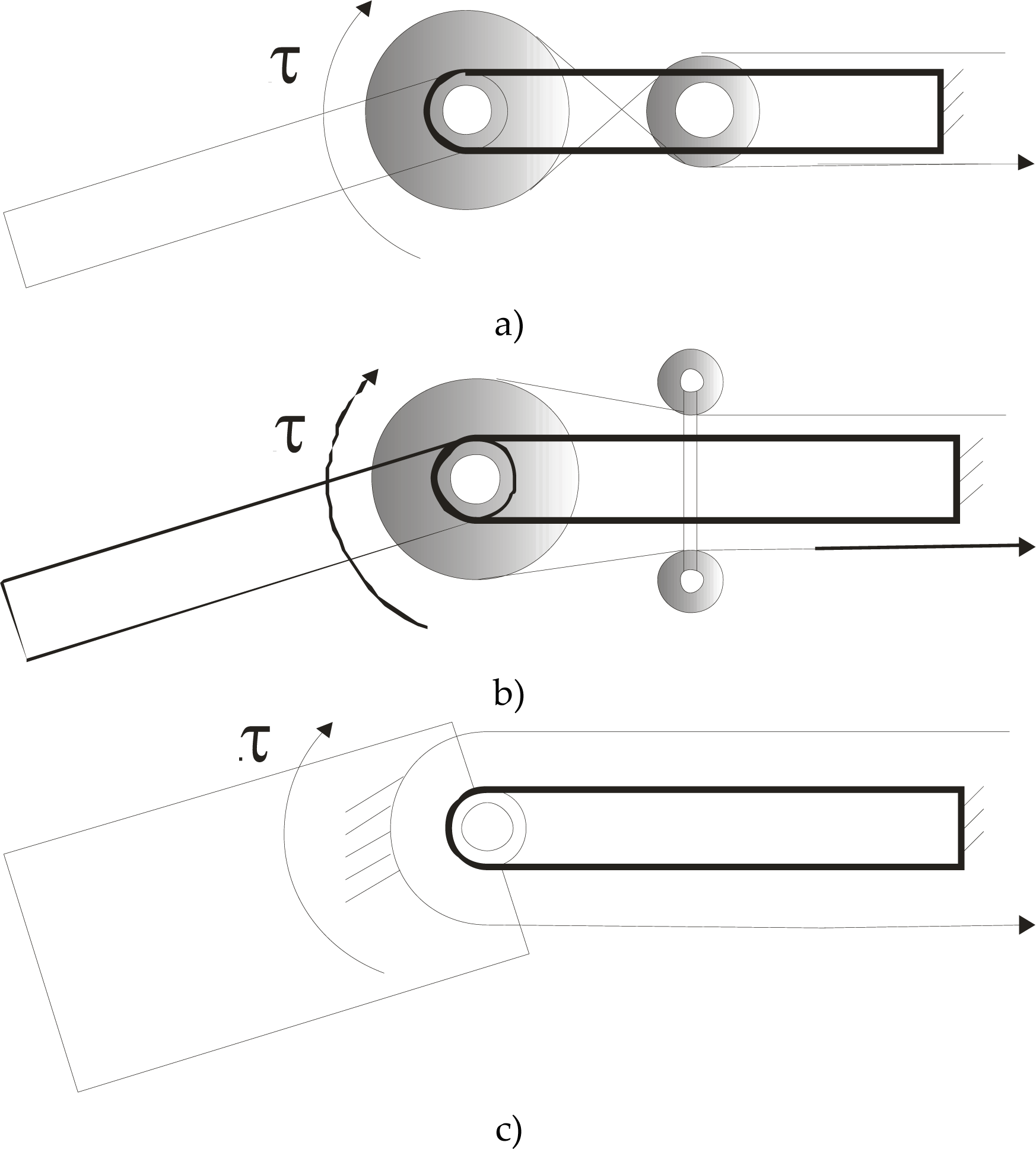
Schemes for a tendon-driven transmission of motion between two phalanxes: a) with a single pulley; b) with double pulleys; c) without pulley
Tendon transmissions can be further divided into solutions using a single pulley, solutions using a double pulley, and solutions without using pulleys, as shown in the schemes of Figs. 2a), b) and c), respectively. FEDERICA Hand is based on a finger transmission without using pulleys, as in Fig. 2c) [16–17].
The transmission without pulleys is the simplest solution among the tendon transmissions. However, this solution may suffer from significant friction losses that must be carefully taken into account at the early design stage.
Linkage transmissions can be divided into mechanisms external to the finger body and mechanisms internal to the finger body, as shown in the schemes of Figs. 3a) and b), respectively. LARM Hand uses a linkage transmission solution where the driving mechanism always remains inside the finger body during the whole movement of the finger. This solution has significant advantages in terms of compactness and safety. However, very careful design is needed to achieve feasible link sizes for a proper mimicking of human grasping [29–31].
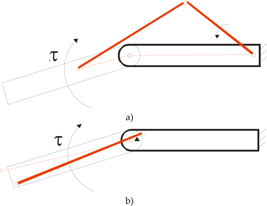
Schemes for a linkage transmission of motion between two phalanxes: a) external to the finger; b) within the finger body
The FEDERICA Hand is composed of five fingers, each made of three phalanxes. Each phalanx is connected with a revolute joint, as shown in the 3D CAD model of Fig. 4. The five fingers are attached to a fixed frame (metacarpus) that is similar to a human palm, as also shown in the image in Fig. 5.

3D CAD model of FEDERICA Hand
Each finger has two antagonistic tendons that are rigidly connected with the distal phalanx as shown in the scheme of Fig. 6. The tendons slide within a specific cavity along the external surface of the whole finger. This design solution allows the transmission of motion to all the phalanxes. Moreover, if the motion of a phalanx is blocked by a constraint, the tendon will still actuate the remaining phalanxes. This feature allows a finger to adjust its shape to the shape of a grasped object. Some characteristics of the proposed FEDRICA Hand design show similarities to a successful mechanical hand designed previously, as described in [19].

A picture of FEDERICA Hand prototype in Naples

A scheme of finger transmission in FEDERICA Hand (1i1 1i2 13 stand for proximal, medial, distal phalanx, respectively)
It is important to note that tendons only work in traction. Thus, FEDERICA Hand has an antagonistic tendon on the upper side of each finger. Each antagonistic tendon is connected to an elastic spring element that brings a finger back to the horizontal/rest configuration when the corresponding active tendon is not actuated.
FEDERICA Hand only requires one actuator for the operation of all five fingers, as an attempt to further reduce control complexity. In particular, a specific set of pulleys has been placed on the palm body, as shown in Fig. 5. All the actuating tendons are connected to this set of pulleys as shown in the scheme of Fig. 7. An external pulling force F is applied to the big pulley by means of a single external tendon. Then, the specific sizes and location of the other pulleys allow the following distribution of the external pulling force F:
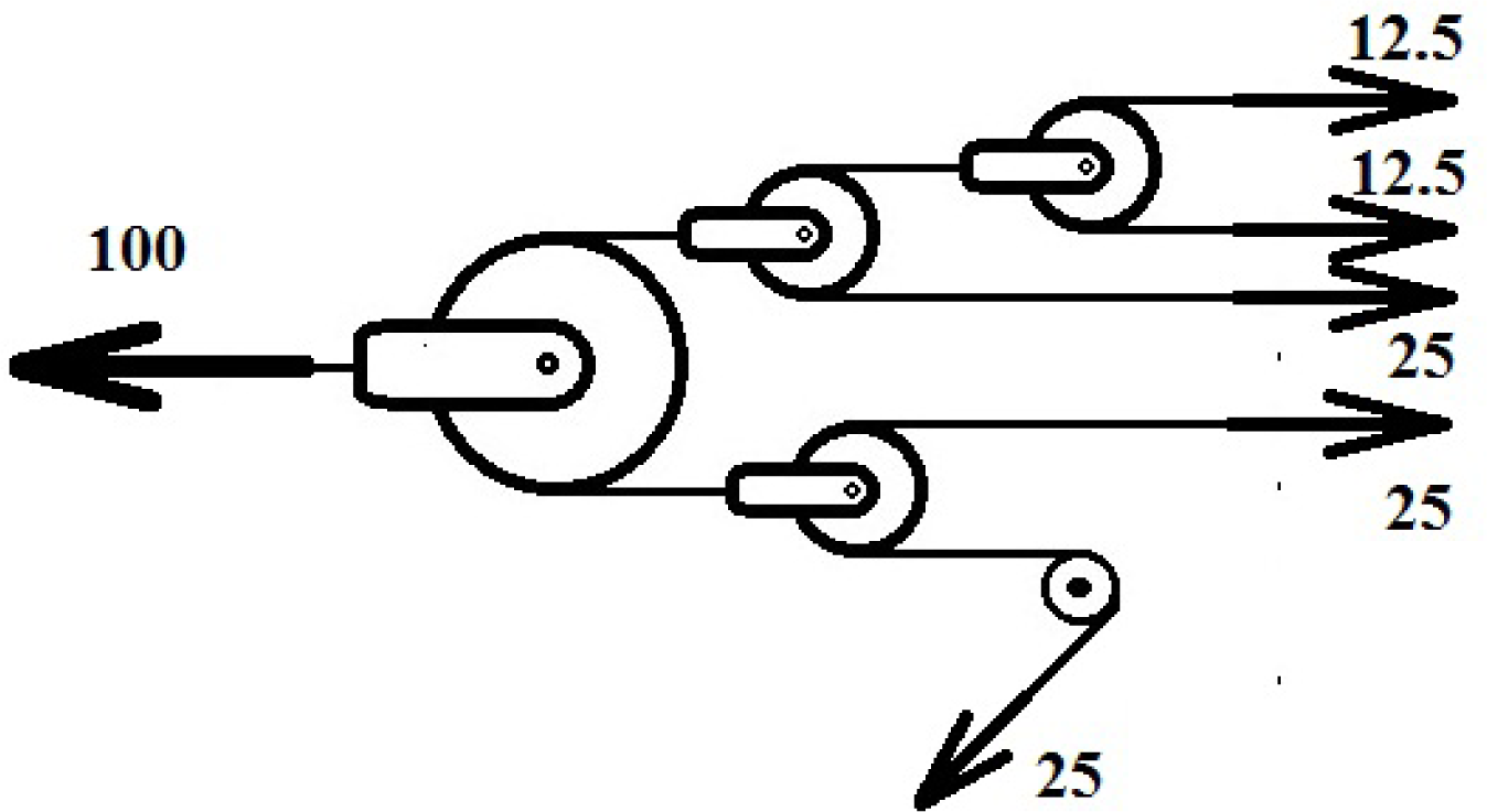
A scheme of the forces' distribution on the set of pulleys in FEDERICA Hand
F/4 (25 %) on thumb; F/4 (25 %) on index; F/4 (25 %) on middle finger; F/8 (25 %) on middle finger; F/8 (12.5 %) on little finger.
The main fingers (thumb, index, middle finger) receive 75 % of the external pulling force while the action of the ring and little finger is limited to the remaining 25 % of the external pulling force. If a finger is constrained to a given configuration, the external pulling force is equally distributed to the other fingers. This feature allows all the fingers to move until they enter into contact with a grasped object by self-adapting the finger configuration.
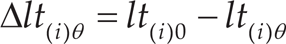
Each finger consists of three phalanxes that are each connected by a revolute joint. One of the joints is active while the other two are passive. For each configuration, the total actuating tendon shortening will be the sum of three contributions. Each contribution to the tendon shortening is due to the rotation of one of the three joints. The scheme in Fig. 8 shows two contiguous phalanges (i-1) and (i) in the undeformed/rest configuration, when the angle between them is θi = 0.

Tendon diagram for two contiguous phalanges in the undeformed condition θi = 0
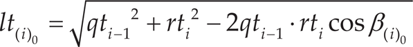
In the undeformed/rest configuration, it is possible to evaluate the distance between the two guides Vi-1 and Vi that represents the length of the tendon lt(i)0. After pulling the actuating tendon, the joint angle will be θi<0 as described in the scheme of Fig. 9. Accordingly, after the pulling, the length of the tendon lt(i) will become

Tendon diagram for two contiguous phalanges in the undeformed condition θi = 0
Additionally, if n is the number of joints, the total shortening of the tendon can be computed as

where the total shortening is a function of the rotations of all phalanges within a finger.
For each joint, one can refer to the models in Figs. 8 and 9 to compute lt(i)0 and lt(i)θ, respectively, in the form

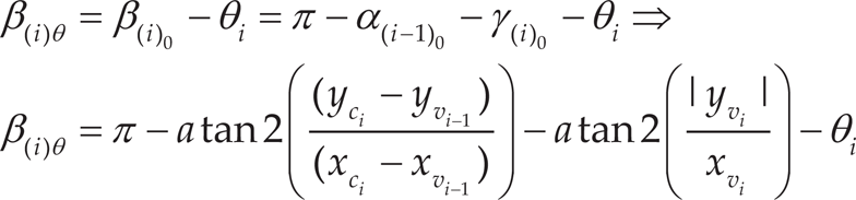
In equation (2) the angle β(i)θ can be expressed as a function of angle θi in the form
Numerical simulations have been carried out in order to estimate the dynamic behaviour of FEDERICA Hand. Figure 10 shows the results of the numerical simulations of a complete cycle of folding and extension of the index finger of the FEDERICA Hand when a pulling force of 17 N is applied on the input tendon. In particular, Fig. 10a) shows the angular motions on each phalanx with a maximum value of about 90 deg.; Fig. 10b) shows a plot of the shortening of the tendon at each joint with a maximum value of about 10 mm; Fig. 10c) shows a plot of the total tendon shortening with a maximum value of about 30 mm. It is worth noting that the tendon shortening is almost equal at each joint.
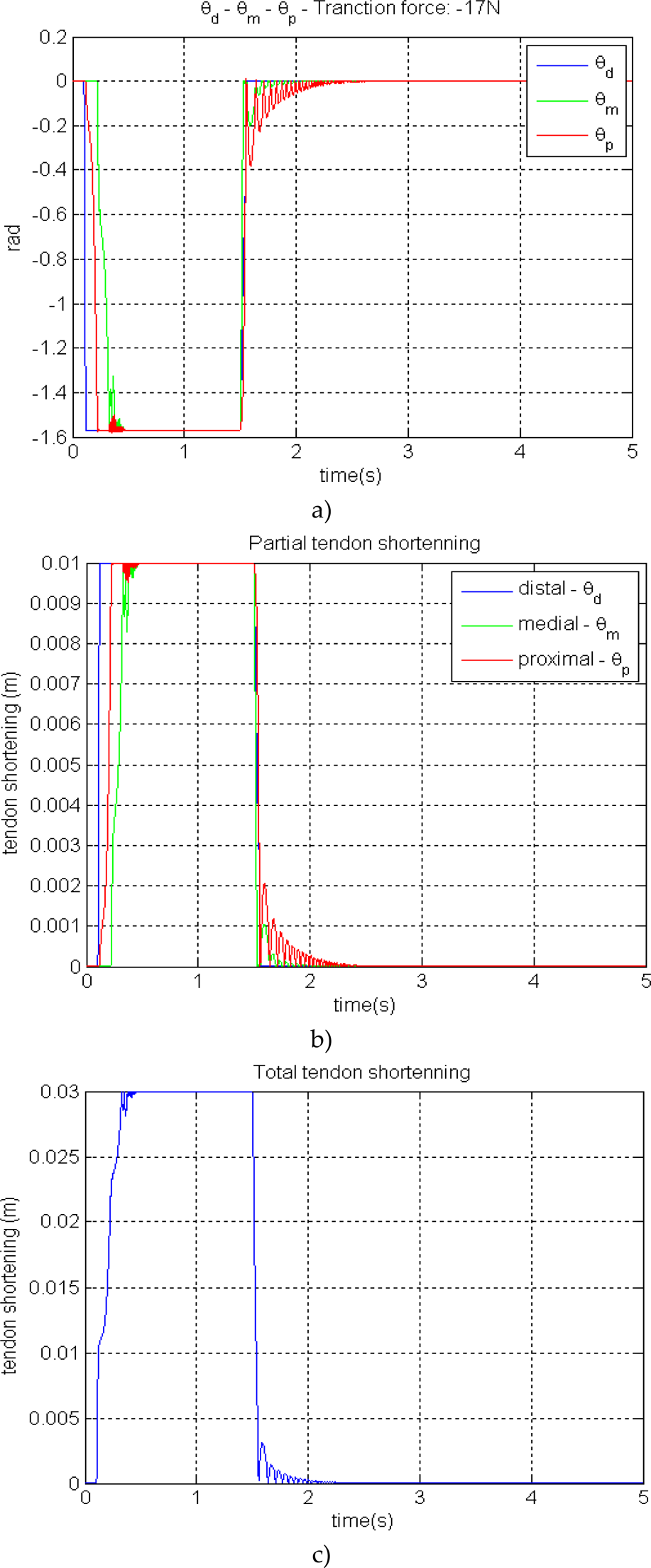
Results of numerical simulations of a folding and extension cycle of the index finger of FEDERICA Hand: a) angular motions on each phalanx; b) shortening of the tendon at each joint; c) total tendon shortening
The motion of each finger is achieved by means of a set of pulleys so that a single actuator can operate all the fingers.
The design of the required pulleys needs to consider both the force distribution among the fingers and the displacement (shortening) of the actuating tendon of each finger.
For a proper design of the set of pulleys, one should start by considering a generic pulley which has a radius R with a tendon on its external surface, as shown in the scheme of Fig. 11.

A scheme of a pulley when a tendon is moving it from an initial configuration (solid lines) to a final configuration (dotted lines)
The extremities of the tendon can be moved by two different quantities: X1 and X2 with X1 > X2. In this case, the pulley will move from its initial configuration (solid lines) to a final configuration (dotted lines).
If XA is the displacement of the centre of the pulley, the quantities X1 and X2 are related to XA and to the rotation θ of the pulley according to the following expressions:


Using Eqs. (6–7) one can calculate the displacement XA and θ of the pulley as function of the tendon displacements X1 and X2 in the form


It is important to note that θ does not coincide with any of the joint angles θi in Eqs. (1–5).
Eq. (8) gives the possibility of computing the displacement of a pulley XA and the shortening of a tendon of a finger. Similar calculations can be made for the whole pulley system. If one refers to the scheme in Fig. 12, one can write the following equations:
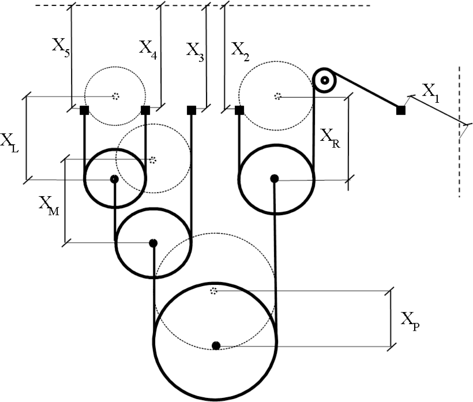
A scheme of the full pulley system for FEDERICA Hand (solid line is an initial configuration; dotted line is a final configuration after pulling the input tendon at a distance XP)


The total shortening of the input tendon of FEDERICA Hand, XP, is a function of the shortening of all five fingers, as computed by Eq. (13). Further details of FEDERICA design and operation can be found in [16–17].
LARM Hand is the name of a series of prototypes that has been designed and built at LARM in Cassino since the beginning of 2000. Four different prototypes have been designed and built (LARM Hand versions I to IV) for grasping objects of different sizes and shapes. For example, Fig. 13 shows a picture of LARM Hand version IV and its specific application for handling tomatoes.

LARM Hand IV in Cassino: a) a built prototype; b) an application task for the handling of tomatoes
The LARM Hand series has been designed by focusing on low-cost and easy-operation features. In particular, the built prototype makes wide use of commercial components such as standard aluminium plates and low-price standard DC motors. Even the control strategies have been developed so that they can be implemented with a low-cost commercial PLC.
The LARM Hand IV prototype is composed of three fingers and a palm, as shown in Fig. 13a). The palm is made of a flat aluminium plate with a plastic cover. The actuation system consists of three DC motors with a planetary reduction gear train on each finger. A DC motor is rigidly connected to the finger frame to make a finger module. A full finger module (including the motor) can be detached from LARM Hand IV just by removing two screws. This solution makes it very easy to change the number and location of fingers.
Figure 14 shows a scheme of a finger of LARM Hand IV with a kinematic model of its driving mechanism. Each finger is composed of two four-bar linkage mechanisms as shown in Fig. 14. The first phalanx (labelled with 1 in Fig. 14a) is the input bar of the first four-bar linkage.
A finger of LARM Hand IV: a) a 3D CAD model; b) a kinematic model for the driving mechanism
The first phalanx is also the base frame of the second four-bar linkage mechanism. The second phalanx (labelled with 2 in Fig. 14a) is the input bar of the second four-bar linkage mechanism, and it is also the coupler of the first four-bar linkage mechanism. Then, the third phalanx (labelled with 3 in Fig. 14a) is the coupler of the second four-bar linkage mechanism.
Referring to the scheme in Fig. 14b), the angular velocities of the second and third phalanxes can be defined as
Both θg and θj can be computed as functions of the input angular velocity of the first phalanx θb = dθb/dt, such as

where one can also replace the angular velocity θC with θb, since both θC and θb are angular velocities of the same rigid body (the first phalanx) with respect to the fixed reference frame. The time derivatives of Eqs. (14) and (15) can also be used for computing the angular accelerations on each phalanx.
The above-mentioned kinematic equations can be used to compute the speed of each phalanx as a function of the input speed or vice versa. Therefore, one can use Eqs. (14) and (15) for verifying that the speed of a phalanx provides human-like behaviour.
A proper size synthesis for the driving mechanism requires taking into account not only the above-mentioned kinematic equations but also several other design characteristics, such as the force transmission. Similarly, several design constraints should be considered: among others, how to keep the driving mechanism within the finger body. Accordingly, the size synthesis for the driving mechanism is quite complex, since many aspects have to be considered at the same time. For this purpose, it has been necessary to define and solve a specific optimal design problem that leads to the main sizes that are reported in Table 1 for LARM Hand IV. A similar optimization process for one finger of LARM Hand III has been reported, for example, in [25]. It achieves optimal human-like motion of the phalanxes, and minimal power consumption under several design constraints.
The mechanics of grasping for hands with three fingers can be very complex according to number and location of contact areas. Thus, further design refinements may be needed for adjusting the built hand for specific grasping purposes. For example, further considerations on grasping with LARM Hand IV have been achieved by means of the model in Fig. 15.
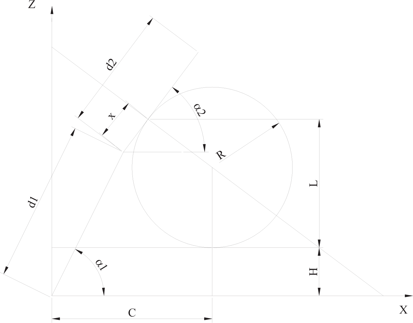
A simplified 2D scheme of a finger while grasping a cylindrical object
Main sizes of the driving mechanism of LARM Hand IV, as referred to in the scheme in Fig. 13 (sizes in mm)

The model in Fig. 15 is a 2D model of one finger of LARM Hand IV grasping an object of cylindrical shape. In Fig. 15, one can notice that there is only one feasible contact point between a rigid object of feasible cylindrical shape and a finger of LARM Hand IV, since each finger has only one DOF. Then, one can compute the feasible contact point by intersecting the analytical expressions of the surface of the object to be grasped with the grasping surface of the phalanxes of a finger of LARM Hand IV. In particular, one can identify the feasible contact point as the intersection of a line and a circle by referring to the planar model in Fig. 15.
By using geometrical relationships one can define the coordinates Xc and Zc of the centre of the circle as

where R, H and C are known values based on the sizes in Table 2 and dl is a known size of grasped object. The values of α1 and α2 can be analytically obtained by considering that the contact point should also be on the surface of the grasping object. Thus, coordinates Xc and Zc should satisfy the equation
Moreover, the driving mechanism has one DOF. Therefore, α1 and α2 are not independent. For the specific sizes in Table 2, one can write

Therefore, one can compute the values of Xc, Yc, α1 and α2 by solving the set of equations given by Eqs. (16–18) and (6). Moreover, by using the known values of Xc and Yc one can find the distance d of the contact point from the beginning of the second phalanx in the form
Referring to Fig. 15, one can similarly compute

The above equations can be used for computing the contact point for cylindrical objects which have radius R from 30 to 50 mm. For example, one obtains α=63.5 deg., α2=53.1 deg., d=12.8 mm, L=37.0 mm for an object with R=50 mm; one obtains α1=56.7 deg., α2=41.4 deg., d=12.4 mm, L= 32.2 mm for an object with R=40 mm; and one obtains α1=48.7 deg., α2=29.9 deg., d=11.0 mm, L=27.3 mm for an object with R=30 mm, as shown in Fig. 15. Similar values have been obtained for the grasping of objects of the same size and shape during experimental tests, as shown in Fig. 16. Therefore, the above-mentioned value of d has been used for selecting the most convenient location for the force sensor on the fingers of LARM Hand IV. In particular, Fig. 16 shows the location that the force sensor should have for cylindrical objects that have R=50 mm, R=40 mm and R=30 mm. Nevertheless, one can note that the location of the force sensor in Figure 16 is suitable for measuring the grasping force for cylindrical objects with radius R from 30 to 50 mm. In fact, the contact points between the above-mentioned objects and a finger of LARM Hand IV always fall within the sensing surface for the force sensor with a square shape and one side of 15 mm.

Contact point of a finger of LARM Hand IV with cylindrical objects
Several simulations have been carried out in MSC ADAMS environment for simulating the operation of LARM Hand IV. The built model in Fig. 17 pays careful attention to the simulation of the expected grasping forces. Accordingly, specific force sensors have been modelled on the expected area of contact with an object, as shown in the model of Fig. 16. Then, numerical results have been obtained, such as the plot in Fig. 18. Further details on LARM Hand design and operation features can be found in [26–31].

A model of LARM Hand IV within MSC ADAMS

Plot of the grasping forces as function of time as obtained using the model in Fig. 17
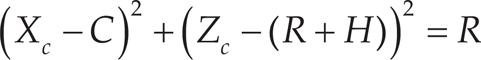
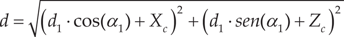
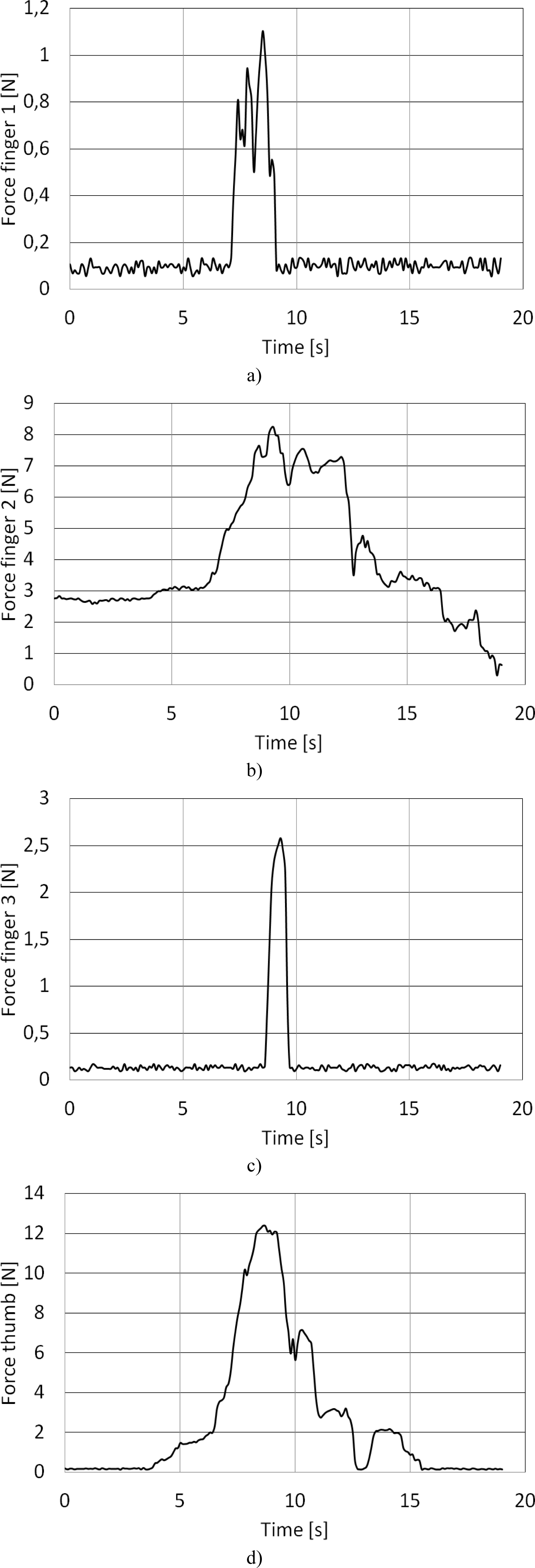
The grasping performance of FEDERICA HAND and LARM Hand IV have been experimentally measured with a simple experimental set-up that is based on a National Instruments NI DAQ 6009 USB acquisition board and four Interlink Electronics FSR150CP12 low-cost force sensors. For FEDERICA Hand, the force sensors have been attached on the thumb, index, middle and ring fingers as shown in Fig. 19 a). For LARM Hand IV, the force sensors are attached to the three fingers and to the palm, as shown in Fig. 19b).
It is important to note that the number of sensors has been limited to four, since only four differential analogue input channels are available on the chosen acquisition board. A suitable virtual instrument has been developed in Lab-VIEW environment in order to manage the data collected by the acquisition board. The operation of FEDERICA Hand has been achieved by applying a known mass to the actuating tendon. The operation of LARM Hand IV has been achieved by means of its on-board PLC programming unit and DC motors. Figures 19 and 20 show an example of the forces that have been measured during the grasping of a bottle of water using FEDERICA Hand and LARM Hand, respectively.
In particular, one can note that for FEDERICA Hand the maximum grasping forces range from about 1 N to about 12 N, as shown in Figs. 20a) and d), respectively.
The maximum measured values of the grasping forces are in accordance with the design requirements and the thumb, index, and middle fingers are the ones that mainly contribute to the grasping while the ring (and little) finger makes a minor contribution to a firm grasping of an object. It is of note that the plots of Fig. 20 have been obtained by applying a known weight of 6 kg that leads to a pulling force of about 60 N. This aspect highlights one of the main drawbacks of the FEDERICA design in terms of very high friction losses and very low mechanical efficiency. Additionally, the use of tendons limits the maximum amount of input force that can be applied in order to avoid undesired tendon failures. Based on the obtained results, FEDERICA Hand shows promising features as a low-cost prostatic hand. User-friendly operation can be easily achieved by operating a single actuator. The pulley mechanism and the tendons make it possible to obtain a suitable self-adapting mechanical feature where each finger is capable of grasping objects with complex shape. But the required actuator should be sufficiently powerful to compensate for the very low mechanical efficiency. Otherwise, FEDERICA Hand can be conveniently used for handling small/delicate objects requiring limited grasping forces.
As regards LARM Hand, the maximum grasping forces range from about 2 N to about 10 N as shown in Fig. 20a) and c), respectively. The maximum measured values of the grasping forces are in accordance with the design requirements. In particular, the sum of grasping forces of fingers 1 and 3 is of the same magnitude as the grasping force of finger 2. In fact, finger 1 and 3 act in opposition to finger 3. It is notable that the plots of Fig. 20 have been obtained by applying a known torque of 0.3 Nm contributed by each of the three DC motors. Comparing the inputs and outputs, one notices that there are very limited friction losses and good mechanical efficiency. It is also important to note that input torque has been limited to 0.3 Nm for safety reasons. However, the chosen transmission system allows considerably higher input torques, and, accordingly, generally higher grasping forces can be achieved if needed. Based on the obtained results, LARM Hand shows promising features for industrial application. User-friendly operation can be easily achieved by operating a single motor per finger. A closed-loop force control can also be properly achieved for the grasping of delicate objects such as tomatoes. The good mechanical efficiency offers the possibility to reduce the sizes and weights of the required motors. Given the characteristics of the transmission system, very high grasping forces can be achieved if needed in specific industrial applications. As for the main drawback of LARM Hand, the limited adaptability to the shape of the objects to be grasped must be noted.

The experimental set-up including FSR force sensors: a) for Federica Hand; b) for LARM Hand IV
Measured grasping forces during the grasping of a 0.5 1 plastic bottle filled with water by Federica Hand: a) sensor on finger 1; b) sensor on finger 2; c) sensor on finger 3, d) sensor on thumb

Measured grasping forces during the grasping of a 0.5 1 plastic bottle filled with water by LARM Hand TV: a) sensor on finger 1; b) sensor on finger 2; c) sensor on finger 3
This work has described the key issues for designing proper robotic fingers with only one active degree of freedom. In particular, careful attention has been paid to the available solutions for driving all the phalanxes with only one actuator. Tendon transmissions and linkage transmission are discussed by referring to the prototypes of FEDERICA Hand and LARM Hand. Experimental tests are discussed in order to show the peculiarities and specific design issues as related to the specific choice of transmission mechanism. Both design solutions show advantages and drawbacks that may make them a better fit for specific applications.