
Abstract
Lab-on-a-chip micro-devices utilizing electric field-mediated particle movement provide advantages over current cell rotation techniques due to the flexibility in configuring micro-electrodes. Recent technological advances in micro-milling, three-dimensional (3D) printing and photolithography have facilitated fabrication of complex micro-electrode shapes. Using the finite-element method to simulate and optimize electric field induced particle movement systems can save time and cost by simplifying the analysis of electric fields within complex 3D structures. Here we investigated different 3D electrode structures to obtain and analyse rotational electric field vectors. Finite-element analysis was conducted by an electric current stationary solver based on charge relaxation theory. High-resolution data were obtained for three-, four-, six- and eight-cylindrical electrode arrangements to characterize the rotational fields. The results show that increasing the number of electrodes within a fixed circular boundary provides larger regions of constant amplitude rotational electric field. This is a very important finding in practice, as larger rotational regions with constant electric field amplitude make placement of cells into these regions, where cell rotation occurs, a simple task – enhancing flexibility in cell manipulation. Rotation of biological particles over the extended region would be useful for biotechnology applications which require guiding cells to a desired location, such as automation of nuclear transfer cloning.
Introduction
Biological cells need to be rotated in many scenarios, such as cell characterization, sorting, and manipulation [1–5]. Over the years, efforts have been continuing in the development of different techniques to investigate cells under rotation [6–8]. By combining molecular imaging probes and microscopy, cell properties can be monitored and tracked over different time periods corresponding to rotational and stationary states. The different cellular behaviour exhibited by different rotation characteristics can be used for various purposes. For example, the morphology, stress, and drug sensitivity of rotating cells have been used in cancer research [8, 9]. Red blood cells have been rotated in an attempt to develop a new method of malaria diagnosis [10]. Furthermore, non-invasive rotation of single biological cells can help construct structured biomaterials such as bio-films, and has application in human tissue engineering [4, 11].
Several phenomena, such as electrokinetics [12], microfluidics [13], and optics [6], have successfully demonstrated cell rotation. Rotation of biological entities by electrokinetics is a technique that has been utilized for many years, and has helped to establish a mathematical base for calculating force and rotational torque on biological cells [14, 15]. Introduction of fluidic techniques has enabled translation of cells using microfluidic channels [16, 17]. However, in microfluidic systems it is difficult to control cell rotation. Over the past few years, opto-electronic tweezers (OET) [18, 19] have been extensively employed to rotate biological cells in an optically-induced rotation field as an alternative. Nonetheless, there are a number of advantages that favour electro-rotation over its fluidic and optical equivalents. The most notable advantages are that electro-rotation induced torque is easily controlled by altering the amplitude and frequency of the electric field, and that there is no need for there to be a direct optical path to the particle to be manipulated.
Rotational ac electric field induced cell rotation is a phenomenon whereby polarizable dielectric particles are subjected to rotational electric fields, giving rise to a controllable amount of rotational torque. These polarizable dielectric particles rotate inside a confined region bounded by the system electrodes. This region within which the particles rotate is defined as the rotational electric field region. In electrokinetics, a constant electric field strength is required to obtain an effective rotation torque to rotate particles [3]. For biological-cell applications, micro-devices are designed with patterned electrodes, which require individual cells to be guided to a specific region in order to obtain controllable rotation. Even though particle rotation through use of rotating electric fields is a well-established approach, guiding cells into the rotation workspace requires skilled manual manipulation. Inserting a single cell at a desired point is often a cumbersome process. Researchers have developed certain automated cell guiding instruments, such as the cell flow cytometer and the fluorescent activated cell sorter [20, 21], to separate each cell type into a desired location. However, these instruments are expensive and substantially increase the associated research costs. Recent advances in micro-manufacturing technology have enabled compact miniaturized devices to be fabricated that facilitate manufacture of cost-effective micro-devices, thus enabling researchers to investigate electric field-based cell rotation [3, 22–24].
Before actual fabrication of any electric field-based, particle rotation lab-on-a-chip micro-device, numerical simulation of the rotational field in the device provides invaluable design information. Researchers have considered factors that are relevant to ac electric field-based rotation, such as analysing higher-order polynomial electrode shapes in order to influence the rotation field dynamics. The conclusion is that polynomial-profile-shaped electrodes provide more suitable rotational-field spatial characteristics compared to square-edged electrodes [25, 26]. Most research has concentrated on optimizing electrode geometry to generate rotational fields to analyse the torque effect on particles. In contrast, our research targets increasing the area of common amplitude ac rotational electric field vectors generated by evenly arranging 3D cylindrical-pillar electrodes in a circular ring. Further analysis is performed in the region enclosed by the electrodes, showing that the arrangement of an increased number of electrodes provides larger and more effective rotational-field regions, thus minimizing the effort required to accurately position particles during manipulation. Generated ac fields are analysed through finite element analysis (FEA). Through simulations, an enhanced device concept is proposed to obtain particle rotation over a large proportion of the device volume.
Theory
Whenever a homogeneous solid dielectric particle sits in a non-uniform or uniform electric field, electric charges will accumulate at the interface between the particle and the medium. Subjected to an applied electric field, positive and negative charge carriers are forced in opposite directions, which give rise to an effective dipole moment across the particle [27–29]. The dipole moment is frequency dependent and characterized by the Clausius-Mossotti (CM) factor (fCM), which is given by:

The parameters
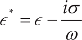
where i=

Equation (3) shows the frequency dpendent property of the rotational torque on the non-zero imaginary part of the CM factor. In a steady-state equilibrium condition, electric field induced torque is balanced with viscous retarding torque, giving rise to a rotation rate or angular velocity measurement αrot(ω), which is given by [30]:

where, ξ is a scaling factor introduced to compensate for the fact that in practice neither the viscosity η nor the electric field strength is precisely known [33, 34]. In practice a scaling factor is defined as a constant for correction of rotation spectra that accounts for the local field strength, frictional force, and electrode geometry [34]. The study of rotational electric field induced angular velocity provides vital information about the properties of particles in suspension. Simulation provides determination of suitable rotational-electric field angular velocity and strength by characterizing the rotation-chamber electric field workspace and electrode geometry. The capability of designing a chamber with a larger rotational electric field region has practical applications in dielectric particle analysis, point-of-care diagnostics and determining cell electrophysiological properties in stem-cell research. [1, 4, 35, 36]
Numerical method
Rotational-electric field torque is a function of the electric field strength, angular velocity (dependent on the amplitude and phase of potentials applied to the chamber electrodes) and frequency, and medium and particle complex permittivity. Thus, analysis of the rotational electric field generated by the micro-electrodes of a proposed chamber design is imperative. Electric field analysis is carried out using charge relaxation theory, in which the flow of electric current through a conducting medium in the quasi-static case is governed by the equation of continuity, which can be written in the form
where σ is the conductivity tensor, Qj is a current source term, which is zero in this study, ∊0 is the permittivity of free space, and ∊r is the relative permittivity of the medium. Under static conditions, the electric potential V is defined by the equivalence:

For the electric field analysis, each electrode is applied with a sinusoidal potential Vm along with a specific phase shift ϕm (where m = 1, 2,‥n for an n-electrode configuration) as:

where A0 is the amplitude and ω is the angular frequency. With the ac voltage as a boundary condition on the electrodes, the resultant rotational-electric field strength, along with rotational direction and rate, is determined.
Numerical methods most commonly used for field characterization are based on the Mie [28, 37, 38] or the finite element theories, and the finite difference time-domain techniques. Finite element analysis (FEA) is adopted to simulate generated electric fields in this research, utilising COMSOL v4.3a. Geometric models are drawn using built-in tools in COMSOL, as shown in Figure 1. A 3000 μm diameter liquid domain is defined and extruded vertically to 500μm. Circular electrodes of 150 μm diameter are evenly deployed on a circle of 1200 μm diameter and also extruded to a height of 500μm. Simulations are conducted in the cylindrical chamber region enclosed by the electrodes on the ring. The spherical particle at the centre is neglected during simulations as rotational fields are being characterized. The ac electric potential boundary condition is applied with a phase-shift interval of 360°//n on each of the n electrodes. In each model a fine mesh is generated of the order of 3.5 × 10⁵ elements and finite nodes. Mesh size was variable depending on the relative change in geometry of the model. Triangular-shaped elements were chosen to form the mesh. On each of these elements the electric field and its gradient were calculated, providing accurate and high-resolution results. A detailed design and model methodology are provided as a supplementary-information (SI) file.

3D model chamber device design arrangements with cylindrical electrodes of height p=500 μm and diameter q=150 μm. (a) Three-electrode, (b) four-electrode, (c) six-electrode and (d) eight-electrode configurations are shown. A spherical particle of 120 μm diameter is shown at the centre of the cylindrical chamber. Electrodes in the four configurations are all evenly placed on a circle of 1200 μm diameter (indicated by the black ring). Buffer medium is deionized (DI) water. A 3000 μm diameter circular buffer medium domain is made up of DI water with a relative permittivity (∊r) of 78, and a medium conductivity of
Previously four planar circular-shaped electrodes were utilized to obtain efficient rotational fields to square electrodes [39]. Most prior studies were aligned towards analysis of electric field properties to determine dielectrophoresis (DEP) force and torque on a particle as a function of its location within the inter-electrode space [7, 25, 30]. However, in this article, 3D cylindrical-pillar electrode designs are analysed for the purpose of obtaining wider electric field rotation regions. Models of a micro-device consisting of three, four, six and eight cylindrical electrodes placed evenly in a circular ring, as shown in Figure 1, are investigated.
Electric field analysis is carried out in the cylindrical chamber. Rotating fields vary with time and frequency, so analysing field strength will provide key information about rotation consistency within the chamber space. Stable rotation of dielectric particles under a rotating electric field depends on a constant field amplitude [3, 30, 40]. To this end, firstly electric fields are analysed at the centre region of the chamber to determine an appropriate rotational-electric field amplitude. Secondly, rotational fields are analysed for electric field amplitude consistency by increasing electrode number in the arrangements within the 1200 μm diameter circular region surrounding the centre. Lastly, the rotational-electric field direction with respect to various time steps within a single period is analysed inside the 1200 μm diameter centre region. Note that, in our simulations, there is no ground applied on the electrodes, and each electrode has a different ac potential applied with different phase shift. Because of the symmetry of the chamber design and the driving signals, the centre of the chamber is at a virtual ground potential. The principle of this type of virtual ground was previously mentioned in [41].
Results and discussion
Electric field strength analysis for varying rotation chamber size
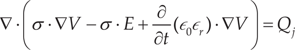
The electric field strength at the centre of the chamber is one of the essential parameters when calculating electric field induced torque on a spherical particle. Figure 2 shows the variation of electric field strength for the three-electrode configuration with different chamber sizes. At the chamber centre the field strength is determined at nine evenly spaced intervals over a single period of ωt=0 to 2π, at 10 V ac amplitude. Only a 10 V amplitude is applied in all the simulations, because the final objective is to analyse and understand the properties of rotational-electric field strength by varying the electrode separation rather than varying electrode potential; also, 10 V is the maximum amplitude many commercial signal generators are able to provide as an output.
Electric field strength at the centre point of the three-electrode-arrangement rotation chamber at nine points in a period. Electric field strength increases with decreasing chamber size. A sinusoidal voltage potential of 10 V amplitude was applied to obtain the electric field strength.
The results show that the field strength at the centre point increases with decreasing chamber size. The amplitude of the electric field for a single period remains constant within each of the different-sized chambers. Even though a constant amplitude of the field strength was found at the centre point of each chamber, the strength of the field varies outside the centre region. The field strength generated with the electrodes positioned on a circle with a diameter between 750 to 1200 μm is suitable to both obtain particle rotation and maintain biological-cell viability [3]. The results shown in Figure 2 enable configuration of the size of a micro-device within which the particle can be rotated. Further, an optimized lower electric field strength will result in decreased thermal heating, thus further preventing cell damage and minimizing buffer streaming due to convection.
The electric field strength at the centre of the 1200μm diameter chamber is determined to be of the order of 0.5 × 10⁴ V/m. Considering the desire to keep the amplitude of the field strength constant over as much of the centre region of the rotation chamber as possible, the rotational-electric field vectors should be generated in some manner to achieve this. Further, an electric field strength of the order of 104 V/m was found to be effective in rotating cells and had a benign or no effect on the viability of biological cells used, matching prior works by others [3, 42].
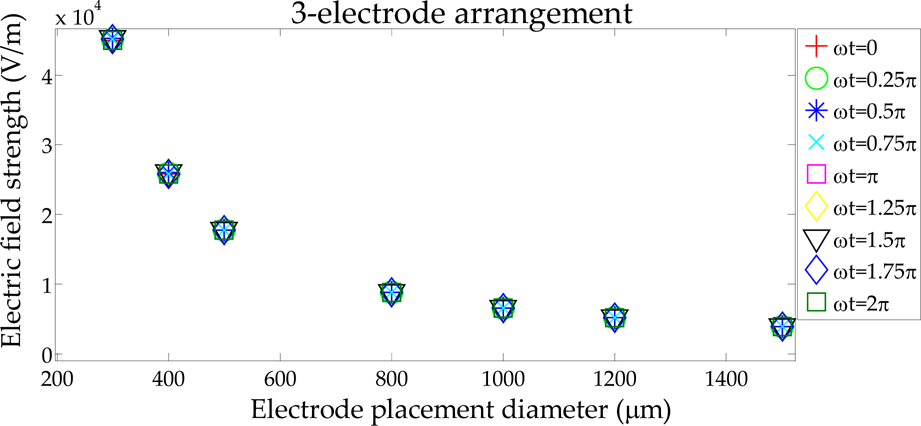
The rotational electric field is initially analysed for strength consistency along a line ±600 μm in length bisecting the chamber. Owing to the symmetry of the system, this then defines a circular area with a 1200 μm diameter. While the distortions introduced by the electrodes are neglected initially, this is a sufficient geometrical approximation to observe the general effect of increasing electrode number. Figure 3 shows the distribution of electric field strength amplitude for three-, four-, six-, and eight-electrode arrangements, respectively. The 1200μm plot of electric field strength variation along the chamber centre line to the electrode edge indicates that as the number of electrodes is increased, the electric field strength also increases in amplitude (given that the applied electrode potential amplitude is unchanged at 10 V peak).
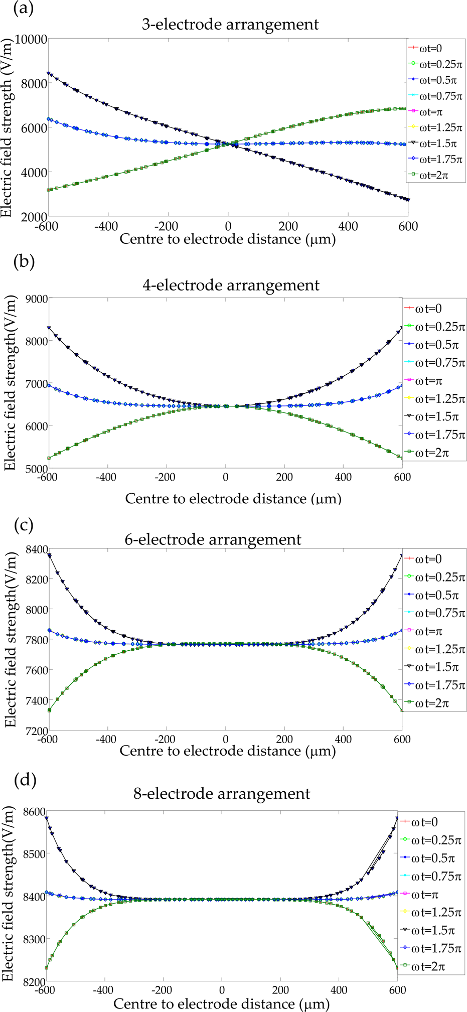
Rotational-field analysis for a 1200 μm diameter electrode placement region. (a) Three-electrode arrangement consisting of uniform rotation field with constant field at the very centre. (b) Four-electrode arrangement consisting of uniform rotation fields with constant field amplitude within an approximately 200 μm diameter region. (c) Six-electrode arrangement consisting of uniform rotation fields with constant field amplitude within an approximately 500 μm diameter region. (d) Eight-electrode arrangement showing uniform constant amplitude rotation region with an approximately 600 μm diameter.
Four-, six-, and eight-electrode arrangements provide usable rotational-field areas because of the uniformity of the rotating fields within an approximately 200μm (for four electrodes) to 600 μm (for eight electrodes) diameter circular region. However, the eight-electrode arrangement yields the largest region of uniform rotational-electric field distribution compared to the arrangements with fewer electrodes. About 25% of the 1200 μm diameter inter-electrode region (assuming a circular area) consists of rotational fields with constant electric field strength for the eight-electrode arrangement, as visualized in Figure 3(d). Hence, the electric field distribution for the eight-electrode chamber is most suitable for applications requiring the maximum rotation region.
Initial electric field distribution results show a greater uniformity of constant amplitude field strength for six- and eight-electrode chamber designs. However, rotational fields further depend upon the configured electrodes' workspace and on angular frequency or time period. Therefore, the field strength needs to be analysed within the workspace over an entire period. For this purpose, electric fields are analysed with respect to different electrode configurations over a single period at an interval of ωt = π/4. A square workspace is defined within the centre area of the chamber with side length of 1200 μm. Fig. 4 shows the rotational-field strength analysis, where there are 3.5 × 10⁵ elements within the 1200 μm by 1200 μm high-resolution square workspace, for the three- and eight-electrode configuration, respectively. It is clear from these plots that the region of constant electric field amplitude is larger for the eight-electrode arrangement.

High-resolution 1200 μm × 1200 μm plots for the three-electrode and eight-electrode configurations. (a)
Table 1 provides data on the average electric field strength (over one period) over the entire 1200 × 1200 μm region.
Average electric field strength at ωt=0

The field strength variation within the three-electrode configuration showed a higher relative standard deviation (STD) percentage variation from the mean compared to the four-, six- and eight-electrode arrangements. The standard deviation percentile is calculated by:

The rotational electric field is a vector quantity. From the initial analysis, it was found that a central region of constant amplitude rotating electric field strength can be obtained. The region of constant field strength expands with an increasing number of electrodes. At the centre point of the chamber, the field strength is always constant in amplitude regardless of the electrode number investigated. The field strength varies to different degrees near the central rotational region for different electrode-number arrangements and also with the applied ac electric field frequency and amplitude. Moreover, the rotational electric field at the centre region of the chamber has an associated rotational direction and rate. Hence, estimation of the electric field rotation vector angular change is required to determine rotating-particle characteristics. For this purpose, we have determined the STD of electric field strength at the centre of the rotation chamber for the arrangements with varying numbers of electrodes, as shown in Table 1. The STD percentile values show that irrespective of the number of cylindrical electrodes, over a single period the rotational electric field strength remains constant and little deviation is seen from the mean electric field strength at the centre point of the chamber. Table 2 highlights that increasing the number of electrodes will increase the region of constant electric strength.
Relative area (percentage of area within the 1200 μm diameter workspace) of constant average electric field strength central to the 1000 μm square centre region

From the 1200 μm-square workspace analysis results, the three-electrode configuration showed rotational-field consistency only at the very centre of the rotation chamber. Within this small area, the field vectors made one complete rotation of 360° in one period. Similarly, the rotational field generated in the four-electrode configuration resulted in a constant amplitude rotational field over a wider, 200 μm diameter circular area at the centre, which is consistent with the results shown in Figure 3. The six-electrode configuration showed effective rotational-field regions with a 500 μm-diameter circular area, again consistent with the results shown in Figure 3. Hence, there is a 53% increase in the constant amplitude electric field strength relative area (% of the electrode chamber workspace) compared to the four-electrode arrangement. The eight-electrode configuration is estimated to have a uniform rotational-electric field region with an approximately 600 μm diameter circular area, resulting in a 47% rise in effective constant amplitude electric field relative area compared to the six-electrode arrangement.
A polarizable dielectric particle is inserted into the configured electrode system to understand the effect of rotational fields, as shown in Figure 5. The 3D system is cut along the xy-plane through the centre z-axis point (250 μm) to obtain a two-dimensional (2D) plane image for analysis in this section. The permittivity and conductivity parameters of the liquid medium and the particle are given in Table 3. A polystyrene bead of 60 μm radius is considered for simulation in this section.
Parameter constants of particles and medium

Parameter constants of particles and medium

FEA simulation of rotational electric field used to rotate a spherical polystyrene bead. (a) Polarized particle with three-electrode arrangement. (b) Polarized particle with eight-electrode arrangement. See supplementary information (SI-1 and SI-2).
Compared to the three-electrode system, the eight-electrode system polarizes the particle much more effectively at the same boundary conditions of 10 V amplitude sinusoidal signal. Contour plots of particle polarization and surface plots of electric field norm are shown in Figure 5. The simulations further show that particles polarize in both cases, but for the eight-electrode system rotational fields consistently polarize the particle, resulting in a uniform rotation rate, as seen in the supplementary videos.
Our objective, however, is to show that increasing the number of electrodes provides wider rotation regions. For this purpose, further simulations were carried out by inserting three spherical particles instead of a single particle, placed 300 μm equidistantly from one another in the rotational-electric field regions. Figure 6 shows three particles rotating under the influence of rotating electric fields. From the analysis, it is evident that the eight-electrode system provides suitable constant rotational electric fields on all the three particles, as shown in the high-resolution plots, whereas the three-electrode system induces unbalanced rotational fields – this can be observed in the rotating-field colour intensities. Detailed simulation and dynamic response of the particle under rotating electric fields are provided as a supplementary file and an animation file along with this article for reference.

Simulation of rotational electric field rotation of three spherical polystyrene beads. (a) Polarized particles with three-cylindrical-electrode arrangement along the xy-plane. See SI-3. (b) 300 μm, high-resolution image, consisting of rotational-electric field regions on the three particles using the three-electrode system (xy-plane cut section). (c) Polarized particles with the eight-cylindrical electrode arrangement. Contour plots show uniform distribution of rotational fields surrounding the particle for the eight-electrode system as compared to the three-electrode arrangement along the xy-plane. See SI-4. (d) 300 μm, high-resolution image, consisting of rotational-electric field regions on the three particles using the eight-electrode system (xy-plane cut section).
Simulation of rotating electric fields on the particle shows that the eight-electrode system is indeed superior. Using FEA, constant electric field-strength data can be extracted on multiple single particles under rotational fields. This constant electric field strength is later used to numerically simulate and analyse the particle rotation spectrum. Experimental data from actual physical tests can then be used to validate the numerical simulations.
The values identified in Table 3 are employed to numerically plot the particle rotation spectrum. The single-shell model is considered for initial estimation of the rotational angular velocity of a normal oocyte using a polystyrene bead for comparison. The oocyte radius R is considered to be 60 μm, and the capacitance and the conductance of the membrane are 1.25 μF/cm2 and 400 Ω cm, respectively. Polystyrene beads of a 60 μm radius with defined permittivity and conductivity are considered for computation. These properties are used to numerically analyse angular velocity of rotation for polystyrene beads and bovine oocytes in comparison to experimental data.
The electric field induced torque from Equation (3) is dependent upon the applied ac field frequency and complex particle and medium dielectric parameters. Therefore, the torque equation reduces to a variable function of the CM factor, leading to the numerical calculation of angular velocity or the torque on the polarizable particles (refer to Equation (4)). Therefore, the dielectric properties of the particle and the buffer medium from Table 3 can be used for calculating the dielectric spectrum numerically. One such rotation spectrum plot is shown in Figure 7, where a constant electric field magnitude of 0.5 × 10⁴ V/m is considered. In this analysis polystyrene beads and bovine oocytes are treated as single-shell solid spherical homogeneous particles to obtain angular velocity plots, and as a solid single-shell model [14, 45] for the numerical modelling. Note that the single solid-shell model provides an approximation for how a bovine oocyte may actually behave in practice, as found in our previously designed biochip [3].

Frequency dependency of particle rotation due to the complex conductivity and permittivity factors of the cell/particle and the surrounding medium. Table 3 is used as a parameter reference to obtain these plots. The negative peak indicates particle rotation in an anticlockwise direction. The rotation rate of the bovine oocyte and polystyrene bead is calculated at an electric field strength of 0.5×10⁴ V/m. The scaling factor is assumed to be 1 for both the bovine oocyte and polystyrene bead.
The rotation rate of the bovine oocyte is higher than the polystyrene bead. Moreover, the two peaks indicate clockwise and anticlockwise rotation of the particles. The negative peak indicates particle polarizability that is more than that of the medium, and the positive peak indicates the reverse. Maxwell Wagner (MW) relaxation can be seen at a frequency of 550 kHz. During this period particle polarizability becomes equal to that of the surrounding medium, making it stationary close to that frequency. This frequency, i.e., that at which particle polarizability reaches that of the medium, is called the critical frequency [46].
In a similar way, a spectrum plot of the particle rotation rate can be obtained by simulating electric fields. Numerical analysis of rotation spectrum plots provides further valuable guidance for designing physical experiments. To serve this purpose, we validated numerical spectra with our previously reported experimental results of rotation of bovine oocytes in the yaw axis (rotation with respect to z-axis, as defined here) [3]. A new plot of these data is shown in Figure 8. Our previous experimental results were obtained by applying 10 V sinusoidal potential within a 750 μm rotational-electric field region. Experimental results indicated that the bovine oocytes act similarly to a solid spherical model, due to the electric equivalency of the oocyte membrane and the cytoplasm [3]. This means that there is no negative peak expected in the rotation spectra.
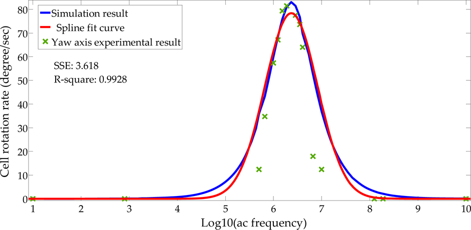
Comparison of simulated and experimental rotation rates of bovine oocytes with respect to the z-axis (yaw- rotation). Electric field strength is 0.6×10⁴ V/m at 10 V ac amplitude. The experimental measured medium conductivity= 3.5 μS/cm, and the relative permittivity is 78. Numerical simulation medium conductivity=5.5e–3 S/m. Bovine oocyte conductivity=5 mS/cm.
Controllable parameters such as electric field strength and medium conductivities were corrected during validation. The close experimental results and numerical simulation values validated the numerical model.
Simulation data of the rotational electric field act as a base to estimate the dielectric spectrum of particles. Electric field induced rotation of a particle is dependent upon the characteristics of the rotating electric field. Simulation results of these rotational fields show that a constant amplitude rotating-field strength is an essential parameter in the practical application of particle rotation, the amplitude being influenced by the configuration of the electrodes and rotational workspace. Further, the results show that wider regions of constant amplitude rotational-electric field strength can be obtained by configuring a larger number of electrodes. This is a new finding, as previously works [3, 25, 39] have limited analyses of electric fields to two pairs of orthogonally arranged electrodes for the purpose of obtaining rotational torque specifically at the centre space. Our work, however, reports key findings and improvements by computing wider electric field rotational regions with constant electric field strength over a varied number of cylindrical electrodes. Wider rotational-field regions imply that a single cell or a particle can be introduced into the chamber at a position not necessarily at the very centre to induce rotation. Instead, the particle can be placed anywhere within a relatively large area about the centre point of the chamber. This is advantageous for manual cell handling in providing flexibility and minimizing difficulty during picking and placing in a wider rotation field region consisting of a constant electric field amplitude.
In past studies, we successfully rotated a single bovine oocyte in multiple axes in an open-top micro-device that included four vertical electrodes [3]. Before construction of this micro-device, it was also numerically modelled by the same FEA method described here. The simulation data from this model were confirmed through biological experiment results [3]. As such, there is high confidence that the simulation data shown here are accurate. Our experience with cell handling for nuclear transfer suggests that an increase of the uniform rotation region in a chamber will significantly aid the process of enucleation.
Conclusion
Electric field based particle rotation depends on electric field frequency, phase shift, electric field strength and polarizability of the particle. Simulation data show that the field strength at the centre point of the chamber remains constant in amplitude irrespective of time and number of electrodes. The chamber size is set to satisfy the desired rotational electric field amplitudes, practical cell-handling operations, and limitations of commercially available signal generators. Electric field vector angular changes are analysed over 3.5×10⁵ elements within a workspace of 1200 μm by 1200 μm square for a single period, yielding optimization of rotational fields with corresponding phase shifts. Eight circular electrodes provide a wider region of constant electric field amplitude compared to the three-, four- and six-circular electrode arrangements. Even though eight electrodes provide a wider rotational-field region, eight equally phase-shifted signals are required for this arrangement. Currently, four electrodes are extensively employed in practice during electric field induced particle rotation. However, providing eight sinusoidal signals with phase shifts would enable effective rotation of a particle with minimal dependence on placement position within the rotation workspace. This condition would be of practical value for biological applications. As the phase difference per channel is constant, and the signal amplitude is the same, the creation of the required signals will be readily achievable.
Footnotes
7.
The authors would like to thank Gary Turner, Helen Devereux and Julian Murphy for technical assistance.
Financial support for P. Benhal was provided by the Department of Mechanical Engineering, University of Canterbury. W.H. Wang was supported by the NSFC (No. 61376120), the One-Thousand Young Talent Programme of China, and the National Instrumentation Project (No. 2013YQ19046701).