
Abstract
Gas detection can become a critical task in dangerous environments that involve hazardous or contaminant gases, and the use of imaging sensors provides an important tool for leakage location. This paper presents a new design for remote sensing of gas leaks based on infrared (IR) imaging techniques. The inspection system uses an uncooled microbolometer detector, operating over a wide spectral bandwidth, that features both low size and low power consumption. This equipment is boarded on a robotic platform, so that wide objects or areas can be scanned.
The detection principle is based on the use of active imaging techniques, where the use of external IR illumination enhances the detection limit and allows the proposed system to operate in most cases independently from environmental conditions, unlike passive commercial approaches. To illustrate this concept, a fully radiometric description of the detection problem has been developed; CO2 detection has been demonstrated; and simulations of typical gas detection scenarios have been performed, showing that typical industrial leaks of CH4 are well within the detection limits.
The mobile platform where the gas sensing system is going to be implemented is a robot called TurtleBot. The control of the mobile base and of the inspection device is integrated in ROS architecture. The exploration system is based on the technique of Simultaneous Localization and Mapping (SLAM) that makes it possible to locate the gas leak in the map.
1. Introduction
The research carried out in this paper has been mainly inspired by the project Robauco [1]. This project's main objective is the development of technologies to obtain mobile robots capable of complex tasks that demand a high degree of autonomy and capacity of collaboration in the presence of human beings. One of the main applications of this line of work is the use of mobile robots in dangerous missions [2] where the environment can be risky for humans (e.g., rescue missions, etc.). In this case, an unmanned autonomous vehicle (UAV) is sent in advance to explore and obtain images of the area. A very desirable feature for these robots is a sensor capable of detecting dangerous gases in the environment.
The same requisite appears within the context of gas leak detection, in a large number of applications in sectors such as the energy and chemical industries [3]. Since inspection tasks are often routine and may appear in dangerous or difficult-to-access places, the use of robotic systems has received considerable attention. Some typical gas detection problems are:
Inspection of pipelines: Pipes are used mainly for the transportation of natural gas (composed of 80 % methane) and hydrocarbons in general. There are lines with lengths of hundreds of kilometres that must be regularly inspected.
Inspection of electrical transformers: Refrigerant and insulating gases with high dielectric constants are often used; for instance, sulphur hexafluoride (SF6), which is also one of the main greenhouse gases.
Leak detection in industrial processes. Both the chemical and the metallurgical industries use in many processes compounds that are toxic to one degree or another. Such industrial plants are constantly subjected to controls of their emissions, and have to inspect large stretches of facilities to locate and repair existing leaks.
The main goal of this work is the design of an imaging system for the remote sensing of toxic or dangerous gases from a mobile robot, to be used in industrial environments. An imaging sensor has the obvious advantage of providing spatial resolution, making it possible to precizely locate the source of the gas. The challenge here is to develop a sensor that is able to provide a ‘gas image’ in real time, at least with semi-quantitative concentration information, being small enough both in size and in power consumption to be placed on a mobile robot.
This paper is organized as follows. Section 2 summarizes the state of the art in gas sensing from robotic platforms; section 3 reviews the principles of infrared remote sensing of gases; section 4 explains the measurement strategies proposed in this work and estimates the minimum detectable concentrations for CH4. Section 5 describes a specific robotic implementation for an imaging gas sensor system operating along the lines proposed in this work. Finally, Section 6 shows the performance of the overall platform.
2. Gas sensing in robotic platforms: State of the art
Gas sensing devices that may be found in a robotic system can be classified into in-situ systems, where in order to obtain the measurement the gas must be in direct contact with the sensor, and remote sensing systems, that provide measurements without contact. Among remote sensing systems, those that provide images deserve specific treatment.
2.1 In-situ systems
To inspect an area, in-situ systems require the robot explore the whole region. Despite this limitation, these sensors are mostly used in experimental robotic systems, primarily due to their low cost and ease of integration with microcontrollers. They are typically encapsulated devices that transduce the variations in the concentration of a given gas into variations of electronic magnitudes (resistance, voltage, etc.), and can be based on a variety of technologies and operating principles [4].
The technology most commonly used for in-situ gas sensors is known as MOX (metal oxide) [5], since it provides high sensitivity for the gases of greater interest, short response time and good stability as compared to other alternatives. MOX sensors are also easily available and very inexpensive devices (although they often require a not-inexpensive prior calibration). On the other hand, one of their major limitations is low selectivity. Although their sensitivity to a specific gas can be increased, they do not respond to a single compound but are sensitive to many gases. To try to overcome this drawback, arrays of MOX sensors are often constructed so that each element has a different sensitivity, although overlapped to some extent with others. The response is then analysed by array-based pattern recognition algorithms to identify and quantify the gas present. This concept was introduced in the 1980s and is known as electronic nose or e-nose [6].
Since the in-situ sensors themselves do not provide information about the position in which the measurement takes place, this information must be obtained by other means. Therefore, despite its widespread use, this type of sensor is not well fitted to the task of locating a leak of a particular gas with enough accuracy for most applications. However, algorithms have been developed to produce maps of concentrations using on-board sensors on mobile robots [7].
2.2 Remote sensing systems
Regarding remote sensing gas sensors for robotic systems, several devices have been used that are based on TDLAS technology (Tunable Diode Laser Absorption Spectroscopy). The measurement principle is infrared (IR) absorption. A single absorption line of the target gas is selected, together with a reference band in which the gas has no absorption. The decrease of intensity at the absorption wavelength is directly related to the product concentration · optical path (ppm · m), as will be explained in the next section. In contrast with MOX sensors this method is very selective, since absorption lines are extremely specific for each gas. Wavelength variation is achieved by using a tuneable laser, which has the advantage of having very low response times that allow the incorporation of detection strategies based on the modulation of both the wavelength and the power employed [8], thus increasing sensitivity.
A specific development for remote measurement based on TDLAS technology is the device known as a Remote Methane Leak Detector [9]. It incorporates lighting from a laser in the near infrared (NIR) next to the detector element; this radiation is reflected by the background, crosses the cloud of gas and is subsequently detected by the detector element. Although these are intrinsically non-imaging devices, when placed on robotic platforms they can be provided with a scanning system that allows the visualization of the distribution of the product concentration-optical path of a specific gas more easily, making them able to locate leaks with greater accuracy and efficiency than in-situ systems.
2.3 Imaging systems
Although it is possible to find different imaging systems for remote sensing of gases (e.g., the GasFindIR system manufactured by FLIR, operating in the absorption band of hydrocarbons [10]), they are still very uncommon in the field of robotics. Currently there are a number of proposals for the development of mobile robots and even unmanned aerial vehicles (UAVs) that incorporate this technology to be employed in inspection tasks. But in spite of this, today is not possible to find a device of this nature that is commercially available [11].
One of the most ambitious projects, developed by the University of Kassel (Germany), is called RoboGasInspector: A Mobile Robotic System for Remote Sensing Leak and Localization in Large Industrial Environments [12]. The project aims at the automation of routine inspection tasks taking place in large industrial plants. A prototype of a mobile robot has been developed that, in addition to a laser scanner and a video camera used for navigation and location, has three sensor elements: a conventional thermal camera in the range of 8–12μm (FLIR model 320), a RMLD device for hydrocarbon detection equipped with a scanning system, and a FLIR GasFindIR camera for gas leak detection. The RMLD device and the GasFindIR camera are dedicated commercial instruments for gas leak detection, but the conventional IR camera can also be used for that application, since leaks frequently produce anomalies in temperature, either cold (due to adiabatic cooling on expansion) or hot (when hot gases escape to the environment).
Although this system marks the current state of the art in the field of robotic systems for remote sensing of gases, no data are presented on the imaging of leaks, and improvement of algorithms both for remote sensing and for leak location are mentioned as future works.
3. Principles of infrared remote sensing of gases
A photon, in order to be absorbed by a material medium, must have an energy that corresponds to the difference between two quantum levels. Transitions between vibration and rotation levels of gas molecules have energies in the IR range and, since these levels are highly specific for each molecule, the IR absorption spectrum of a gas is a ‘spectral signature’ that uniquely identifies each chemical species. Homonuclear molecules, however, such as O2, N2, or Ar, do not absorb IR radiation, because vibrations or rotations do not change their dipole moment. This is in fact an advantage for IR remote sensing of toxic or pollutant gases, since the major components of atmosphere are transparent in that spectral band. On the other hand, typical examples of compounds with infrared signatures [13] are carbon dioxide (CO2), carbon monoxide (CO), hydrocarbons (CxHy), nitrogen oxides (NOx), sulphur oxides (SOx), VOC's (Volatile Organic Compounds), and sulphur hexafluoride (SF6), among many others.
Infrared absorption makes possible not only the identification, but also the quantification, of gases. When an electromagnetic wave strikes an object it can be, to a greater or lesser extent, absorbed, transmitted and reflected. If we represent by α, τ, and ρ the respective energy fractions (called absorptance, transmittance and reflectance), the following relation is fulfilled according to the principle of conservation of energy:

If, instead of a solid or liquid object, we consider a region inside a gas (like, for instance, a pollutant leak), reflectance is zero (ρ =0), leading to:

Transmittance at a particular wavelength depends on the concentration of the gas and the optical path travelled, as given by the Beer-Lambert law [14],

where :
I0 is the intensity incident on the medium.
I is the intensity remaining after being absorbed by the medium.
a(T,λ) is a gas-specific parameter called absorptivity, that depends on wavelength and temperature.
c refers to the concentration of a specific gas.
l is the distance the radiation travels through the medium, usually known as the optical path.
Values of absorptivity are well known for the main gases, and can be found tabulated in databases like HITRAN [15]. Figure 1 shows a typical transmittance spectrum obtained with HITRAN on the web, a web implementation of HITRAN [16]. The gas is CO2, but the overall pattern is similar for all gases: a large number of individual narrow lines (for ambient temperature and pressures, typical widths are less than a nanometre) grouped in bands of characteristic profiles, that may be several hundreds of nanometres wide. This extremely strong spectral structure can be used to an advantage in gas detection, because signal and reference spectral channels can be defined by using wavelengths with and (respectively) without IR absorption. This is done at the line level in TDLAs, but can be done also at the band level using interference filters, whose bandwidths in the medium IR band are typically in the range of a few tens of nanometers; i.e., wider than absorption lines but narrower than absorption bands.
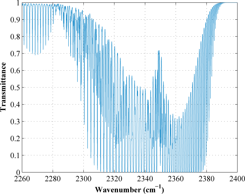
Transmittance spectrum for a path of 1 m, 0.1% CO2, at 296 K and 1 atm total pressure. The x axis is in units of wavenumbers, v = λ−1. A vibration-rotation band, spanning several hundreds of nanometres (the scale ranges from 2250cm−1 =4.44μm to 2400cm−1 =4.16μm) is made up of several hundreds of very narrow individual absorption lines.
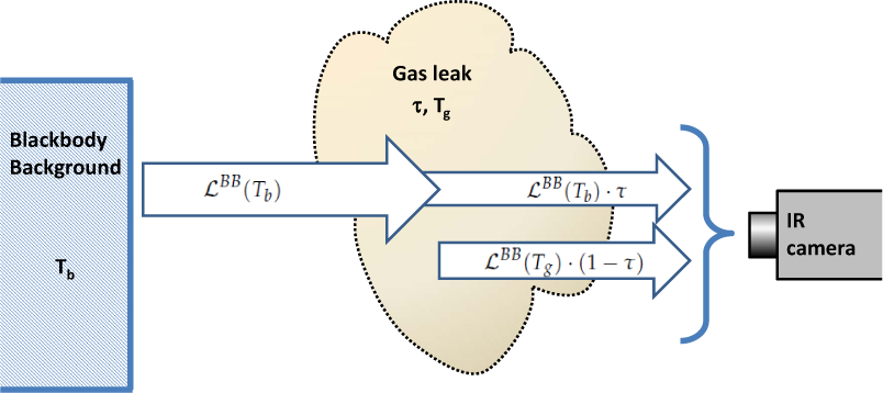
Infrared gas detection need not be based on radiation absorption, since gases also emit radiation at the same wavelengths where they absorb. As in any other substance, the emitted radiance (W / m2sr) is given by
where ℒBB(Tg) is the emission of a blackbody at temperature Tg (given by Planck's law) and ε(λ) is a gas-specific parameter called emissivity, 0 ≤ ε ≤ 1. In fact, since Kirchoff's law states that under the condition of thermodynamic equilibrium the absorptance α equals the emissivity α = ε, it turns out that for a gas ε + τ = 1 and thus ε = 1 − τ. Therefore, calculation of the transmittance spectrum provides also the emission spectrum of the gas, provided its temperature is known. On the other hand, for a solid, τ = 0 and ε = 1 – ρ. For a blackbody, ρ = 0 and ε = 1; for a perfect reflector, ρ = 1 and ε = 0.
4. Measurement strategy
Any gas with an absorption band at an atmospheric window can be, in principle, detected with an IR camera. The simplest approach is to provide the camera with a band-pass spectral filter centred at the band. Due to absorption, the leaking gas will be seen as a dark region against the background. This one-band, passive approach is used in commercial systems as the well-known FLIR GasFind IR.
4.1 Radiometric model
This simple idea must be precize, however, since it focuses only on the IR absorption of the leak, but ignores its emission. A simple radiometric model is necessary in order to understand the problem.
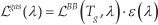
Suppose the background is a blackbody and, at wavelength λ0, the gas leak has a transmittance τ and the clean atmosphere is transparent. The radiance ℒleak (W / m2sr) coming into a camera that looks at the leak against the background (Figure 2) is the sum of two terms: background radiation that has travelled through the leak (and has been partially absorbed) and radiation emitted by the leak:
A scheme of the measurement configuration, assuming blackbody background and no external illumination
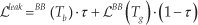
where ℒBB is Planck's blackbody radiance, Tb and Tg are, respectively, temperatures of background and gas, and we have used that ε = 1 − τ. The radiance outside the leak region, ℒnoleak, is simply:

And thus the contrast between the no-leak and leak regions is:
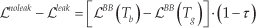
Clearly, if Tg = Tb, ℒnoleak − ℒleak = 0, i.e., the leak will be indistinguishable from the background. Thus, this one-band, passive approach to leak detection only works insofar as the gas shows a thermal contrast against the background.
This is very often the case, since gases from conduction at ambient temperature are cooled considerably by adiabatic expansion as they leak (whereas cooling of very hot leaks is usually not complete near the leak point). However, thermal contrast is not guaranteed in all cases, and since it is weighted by a 1 − τ factor, it may be very small for small leaks (τ near 1), that can be very difficult to detect if their temperature is not very different from the background. In addition, this method is prone to false alarms, since any variation in background temperature can be mistaken for the presence of a leak. In fact, with a complex, non-uniform background, as is usual in an industrial environment, there is no way based only on the radiance values to tell a leak from a background feature. Commercial systems use processing in the temporal domain, taking advantage of non-stationarity in the gas flow of leaks, to discriminate them from other variations in apparent temperature. However, although time processing is a possibility that is always open, it seems advisable not to rely on time variation as the main criterion for gas leak identification, since otherwise a gas leak with laminar stationary flow will be undetectable.
As a first step to a more in-depth study, let us relax the assumption of a blackbody background and suppose, more realistically, a nonzero reflectance ρ b (and thus a background emissivity 1 − ρ b ). Now, for an ambient temperature Ta, the radiation coming out of the background is ℒBB(Tb) · (1 − ρ b ) + ℒBB(Ta) · ρ b . This reduces to the previous blackbody value ℒBB (Tb) if Ta = Tb, but otherwise is (usually slightly) different, which means that now ℒnoleak == ℒleak ≠ 0 for Tg = Tb. However, this does not mean any improvement in gas detection but simply that, since the background is no longer a blackbody, the condition of no thermal contrast is achieved when it has a temperature that is different (but usually not much) to that of the gas.
If a non-blackbody background is assumed, a strategy to improve gas detection becomes possible: to use an external source to illuminate the scene, thereby changing the background radiation. This means using an active scheme, instead of the passive approach described so far. If the radiance of the source is ℒs, an additional term ℒs · F · τ2ρ b will be added to the radiance coming into the camera, where F is a geometrical term that takes into account the solid angle of the source as viewed from the background, ρb is the reflectance of the background, and τ2 appears because the light of the source travels twice through the gas. It is clear that this term will increase the sensitivity to gas concentration, irrespective of its temperature. In addition, a term for reflected ambient radiance has to be included (Figure 3).

A scheme of the measurement configuration, for a non-blackbody background with external illumination
Thus, according to the use or lack of use of external illumination, we have the following cases:


The contrast between the no-leak and leak regions calculated previously (eq. 2) corresponds to the difference between values of eq. 3 for the cases τ ≠ 1 (no leak) and τ = 1 (leak), when Ta = Tb.
4.2 Minimum Detectable Concentrations
In order to compare the passive and active approaches, values of ℒoff and ℒon in equations 3 and 4 have been calculated for a CH4 leak. This gas has been chosen because of its importance in industrial environments, although analogous calculations can be made for most pollutant gases. Concentrations have been varied from c = 0% to c = 100%, with an optical path of l = 10 cm and a temperature T =280K. Background temperatures ranging from Tb = 250K to Tb = 310K have been considered, and emissivity has been fixed at ε = 0.8 (so that ρb = 0.2). This is a relatively high value, to prevent a bias against passive modes in our simulation. The ambient temperature has been fixed at Ta = 280K, although the results are largely independent from it.
Planck's spectral blackbody equation has been used to obtain ℒBB (in units of W / m2sr) for the different Tb, Tg, and Ta temperatures. The source has been modelled by a greybody with ε = 0.75 at 1150 C and an area As =0.2 cm2, that, by means of a parabolic reflector, focuses its radiation on an Ab = 50×50cm2 area of the background. Thus, the geometric factor is F = As / Ab = 8 · 10−5. The source parameters are based on the specifications of the IR-18 infrared source manufactured by HawEye Technologies, with a power consumption of 18 watts [17], illuminating the background from a distance of approximately 2 m.
The transmittance spectrum has been calculated using eq. 1, with the absorptivity provided by the HITRAN database. An interference filter was assumed, with a bandpass 375nm wide, centred at the CH4 absorption band at λ0 = 3.3 μm. The detected radiances ℒoff and ℒon were calculated by integration of equations 3 and 4, respectively, over that spectral channel.
In this measurement approach, the signal is defined as the variation in ℒoff or ℒon due to the gas leak; i.e., the difference in ℒ between values calculated, respectively, with the leak gas concentration and zero gas concentration.
The measurement noise can be estimated from the IR camera data. The key parameter is NETD (noise equivalent temperature difference). A typical value for a modern MIR camera operating in the 3 to 5 μm band with a quantum detector cryogenically cooled (for instance an InSb focal plane array) is 15 mK @300K. This means that the noise rms value is the difference between the radiances emitted in the whole band by two blackbodies at, respectively, 300.015 K and 300.000 K. We have preferred, however, to be conservative and use a larger NETD value, namely 50 mK @300K, which is reasonable for uncooled microbolometer arrays, cheaper and with lower power consumption. Noise expressed in radiance units is then 3.4 · 10−3W / m2sr. It is assumed that this value is not changed by the use of the interference filter.
Figure 4 shows (at the top) the graph of signal vs. CH4 concentration for three different background temperatures, without external illumination (in all cases l = 10 cm, Tg = 280K, and Ta = 280K). Noise level is represented by the horizontal line. It is clear that signal-to-noise ratio (SNR) depends heavily on the background temperature, and, as expected, when there is no thermal contrast between gas and background (i.e., for Tb = 280K), the leak is undetectable. In comparison the graph at the bottom in the same figure shows that introducing illumination greatly improves gas detectability.

Signal (defined as
Results can be neatly summarized if the minimum detectable concentration (MDC) is defined as the gas leak concentration that gives a SNR = 1 value. Values of MDC in active and passive modes for different background temperatures, obtained from Figure 4, are compared in table 1 (always for the 10 cm path).
Minimum Detectable Concentrations (MDC) using passive and active methods for Tb(K) at CH4 and for several background temperatures. In all cases, calculations assume that the optical path is 10 Tg = 280K and the MIR camera has a 50 mK @300K NETD and used an interference filter with 375 nm spectral centred at the cm = λ0 3.3 μm absorption band.

It must be pointed out that MDC values have been calculated assuming a normal incidence for the background illumination. For a tilted background, a cosine factor appears in the F factor, and the ΔL value plotted in Figure 4 is reduced accordingly. MDC values are therefore increased, as shown in figure 5.

Minimum detectable concentration for a 10 cm path of CH4 as a function of the tilt angle of the background, for Tb = Tg = Ta = 280K. For a 45 angle, MDC increases to 1.36%, as compared to 0.69% for normal illumination.
4.3 Scene simulation
In order to get a more graphical feeling of the IR scene, a simple simulation has been performed using the data of the previous section, as follows. We assume the background is divided into horizontal regions of temperatures Tb = 250, 270, 280, 290 and 310 K, ordered from top to bottom. Emissivity is, as previously, ε = 0.8. Between this background and the camera, we suppose there is a gas cloud at Tg = 280 K with a Gaussian concentration profile in the horizontal dimension (standard deviation of
With these data, synthetic images have been constructed for ℒoff (Figure 6) and ℒon (Figure 7). Referring first to Figure 6, the gas leak (at Tg = 280K) is seen as a dark cloud against the hot background (Tb = 310K), and as a clear region against the coldest background (Tb = 250K), although in this case, the positive contrast is much smaller than the negative contrast in the hot background. When Tb = Tg, as in Profile 2, the leak is invisible even in the ideal case without noise. On the other hand, profiles for the active mode (Figure 7) show that there is a much better contrast for all the backgrounds and it is negative in all cases.

(Top) Synthetic image of the radiance ℒoff (passive mode). Five horizontal regions, with background temperatures Tb = 250, 270, 280, 290 and 310 K (from top to bottom) can be appreciated. A CH4 gas cloud, uniform in the vertical direction, with a thickness l = 10cm, and with a Gaussian concentration profile in the horizontal direction (minimum transmittance τ = 0.52) extends between the background and the camera. (Bottom) Horizontal radiance profiles for three different background temperatures. The continuous lines are the values without noise.

(Top) Synthetic image of the radiance ℒon (active mode), for the same conditions of Figure 6. (Bottom) Horizontal radiance profiles for three different background temperatures. The continuous lines are the values without noise.
5. System implementation
In the previous section an approach to design an imaging sensor able to detect pollutant gases remotely with a good SNR ratio, even when the gas has no thermal contrast with the background, has been proposed. The approach is based on the use of an IR camera equipped with an interference filter and an IR source to illuminate the scene (i.e., operating in active mode). In this section, a specific implementation of this design is worked out, in order to demonstrate its viability as a robotic sensor system. We will describe it in two parts: first, the inspection system (i.e., all the required elements to perform the remote sensing tasks) and then the robotic platform (including the mobile platform, the robot software and the robot exploration system).
5.1 Inspection system
The components of the inspection system are summarized as follows:
Although quantum detectors have the best NETD figures, they are relatively expensive and need cryogenic cooling.
On the other hand, due to recent developments in microbolometer sensing technology, now there are uncooled detectors with good enough performance for gas detection. Microbolometer technology represents an improvement in terms of cost, weight and power consumption, which are critical parameters for a robotic system implementation. They have also the advantage of covering a wide spectral range, including both medium and thermal infrared regions. This feature provides high versatility to the proposed design, since several compounds can be detected simply by selecting interference filters matched to the gas spectral signature. For these reasons, a Vanadium Oxide (VOx) microbolometer core from SCD (Semiconductor Devices) manufacturer has been chosen. Specifications of this detector are shown in the following table 1.
Summary of the main parameters for the selected SCD core. NETD value corresponds to optics with an f-number F=1

Depending on both the working distances and the size of the gas leakages to be detected, the focal length of the system will be established. Radiometric constraints such as detection limit, false alarm probability, and so on might be taken into account to define other key parameters as F number, spectral transmittance or coatings. In this initial prototyping stage, a simple optical system based on a 35mm focal distance and 1.1 F number is chosen for its use in short distance environments.
As has been previously mentioned, an active infrared source will be required to enhance the detection limit. Once this parameter is fixed, radiometric specifications will be mainly determined by the working distance and the area covered by the optical field of view. Since power consumption is an important constraint at this application, radiative efficiency must be properly managed through the use of reflectors. The IR-18 infrared source from HawkEye Technologies has been chosen, whose main parameters are described in table 1. In the present prototype the source is fixed, pointing forward horizontally. Taking into account the angle dependence of the measurements, the addition of a pan/tilt system will be considered.
Summary of the more relevant parameters for IR-18 source

It is important to previously define which application will host the processing of the acquired data. For tasks that involve only detection, this can be carried out on board, from an embedded system, but to implement the proposed quantization algorithms in an operative robot it might be more reasonable to transmit data to another point with higher processing capability. In the present prototype version, however, the simplest solution (i.e., an onboard laptop computer) has been used.
Components described are shown in Figure 8.

Two views of the embedded inspection system
5.2 Mobile platform
The mobile platform involves the hardware design and the software that controls it. Both items are described in the following subsections.
5.2.1 Robot description
The mobile platform, where the gas sensing system is going to be implemented, is a robot called TurtleBot [18] (Figure 9). It is a round shape robot of 36cm of diameter and 10 cm height, which is made up of a Roomba base, a Kinect motion sensor attached to it and a laptop that takes care of all the communications among the devices and where the navigation software and the gas analysis algorithms are installed.
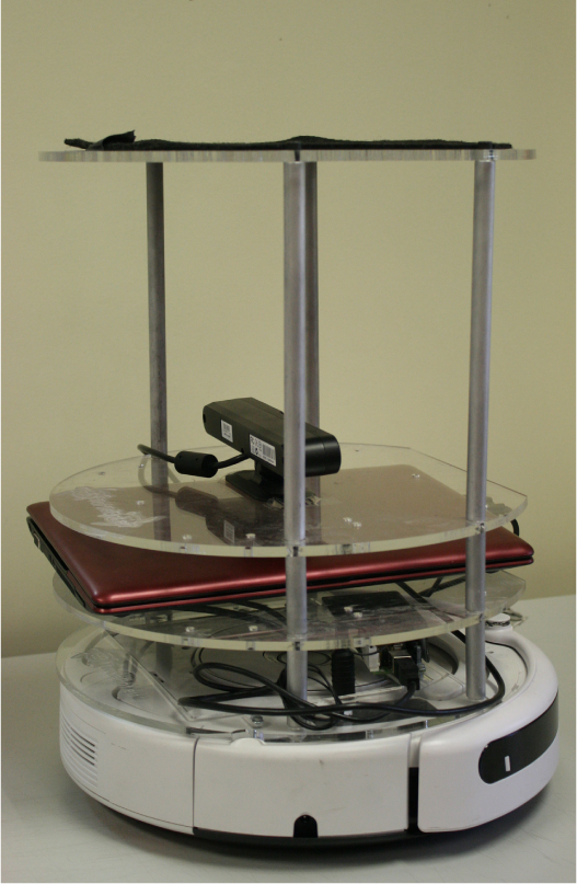
Turtlebot robot used as mobile platform for the inspection system
TurtleBot is a low-cost, personal robot kit with open-source software for indoor navigation and is used as a robotic experimental platform to test robotics prototypes in our labs. Its weight is about 5 kg and it allows a load capacity over 5 kg, enough to carry the inspection devices. The robot can move around and detect the environment while it is moving using a Kinect [19] used as a range finder telemeter for the navigation system of the robot. It can create a map of the area to be inspected and can locate the detected leaks over the map. Its maximum speed is 0.65 m/s, but it can be reduced according to the inspection algorithms.
The batteries of this autonomous robot are located inside the base, featuring an autonomy up to two hours of continuous work. Finally, the hardware of the robot is completed with a modular structure to locate the inspection devices and the ultraportable, high-performance laptop in which the mobile platform and the inspection device are connected for its control. The laptop works under the Linux operative system using ROS (Robotic Operative System [20]) as a framework.
5.2.2 Robot software architecture
The control of the mobile base and of the inspection device is integrated in ROS architecture [20]. ROS is an open-source software widespread use which allows the development robotic applications and their integration in a single framework. It includes a collection of tools, libraries and conventions that seek to simplify the tasks of creating software for Advanced Robotics in a robust way. ROS, rather than a framework, has the functionality of an operating system on a heterogeneous cluster. ROS provides the standard services of an operating system such as hardware abstraction, low level device control, implementing functionality of common use, messages exchange between processes and package maintenance. ROS is based on graph architecture, where the processing takes place in the nodes that can receive, send and multiplex messages from the sensors, control, states and planners, among others.
ROS has two basic components:
The part of the OS, ROS, as has been described above, and ROS-pkg, a suite of packages provided by the contribution of the users (settled in groups called stacks) that implement functionalities such as simultaneous mapping and localization, planning, perception, simulation, etc.
The low-level tasks components for sensor access, diagnosis reporting, power management, etc., that are transparently handled by ROS. This allows the development of controllers and higher-level tasks for a variety of platforms.
TurtleBot can be managed by ROS through its robotic software development environment. It includes an SDK for the TurtleBot, a development environment for the desktop and libraries for visualization, planning, perception, control and error handling. The software tools are completed by some other developments using C++, OpenCV as the available image processing library and software implementation to control the inspection devices and for the inspection algorithms.
Figure 10 shows the software components involved in the robotic control system under the ROS operating system.

Software architecture of the robotic system
Main components of the software architecture are:
ROS as operating system and as manager of high level task and of the control of the robot.
A robot task module, which coordinates the path planner, the SLAM navigation tasks and completes the map information with the location of the leaks.
Robot control module, which manages sensorial information for navigation, actuators, and the I/O communication with the inspection device.
All components are encapsulated in ROS nodes and use ROS topics as a means of information exchange.
For the development of this work, ROS Groovy under Ubuntu 12.04 LTS was used. C++ language was used as the programming language.
5.3 Robot exploration system
The exploration system is based on a technique called SLAM (Simultaneous Localization And Mapping) [21]. SLAM enables the location and building of the map of environment simultaneously when the robot is moving.
ROS has several packages to carry out the SLAM technique using vision. For the development of this work the gmapping package was used, which provides the basic functionality for the exploration algorithm. Several modifications have been carried out on this package in order to integrate the information related to the detected leaks.
The implementation of gmapping is based on the Rao-Blackwellized particle filters to solve the SLAM problem. This approach uses a particle filter in which each particle carries an individual map of the environment, using adaptive techniques to reduce the number of particles in a Rao-Blackwellized particle filter for learning grid maps. The approach computes an accurate distribution, taking into account not only the movement of the robot but also the most recent observation. This drastically decreases uncertainty about the robot's pose in the prediction step of the filter, applying an approach to selectively carry out resampling operations which reduces the problem of particle depletion.
In order to sense the environment, a long-range laser scanner is needed. In this work the kinect is used as a long-range laser sensor, providing an inexpensive alternative to traditional laser scanners, by cutting a horizontal slice out of the Kinect image and using the nearest distance (closest depth) in each column.
Using this technique, the robot can locate itself in an unknown environment. The robot starts its exploration task, navigating, building the environment map and placing itself in it simultaneously. The algorithm has been completed so that, once the leak is detected, the information about its position and parameters is added to the map.
The developed algorithm is shown in Figure 11. All software modules involved in the robotic systems are implemented as ROS nodes. The navigation task starts with an inspection order as an ROS topic, which starts the Planner and Navigation modules. Sensorial systems such as Kinect or gas detector modules are launched by the system thought a roslunch command at the beginning.
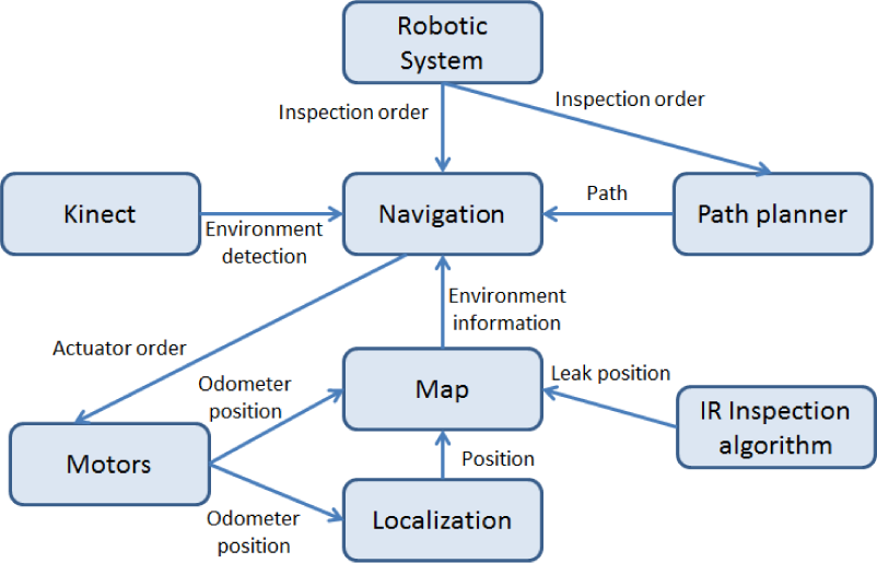
Implemented Inspection algorithm based on the SLAM technique
The navigation module starts to move the robot following a path using the Fast Marching Square technique [22] if it is given previously. If not, a contour following policy has been defined as the default movement. The robot starts to build a map of the environment with the Kinect sensor and the odometry, using the information of the stored map to locate its position on it. Sensorial information from the kinect and from the odometry are also shared among modules through ROS topics.
Once the map is generated detected leaks are added to the map, taking into account the position of the robot obtained in the SLAM process and the estimated position of the leak to the robot.
The proposed exploration system contemplates two operation modes:
Inspection task: If the map is a priori known, as is the case for most of the industrial plants, the possibility of establishing the previous inspection routes, limited to locate the robot and the leak within the map, is considered. In this case the navigation system of the robot follows the path, avoiding obstacles, relocating the robot on the map and adding the leak position and information to the map.
Exploration task: If the map is not known, as is the case where the robot works in an emergency situation or in an unknown scenario, without previous information, the robot is able to start to navigate using predefined skills such as contour following in order to build the map, locate on it and add the leak position and the information in the map in a simultaneous way.
6. Overall platform test
The test environment for the full prototype consists of a room in which several gas pipes run parallel to the walls. Due to the extreme flammability of CH4, and the difficulties in handling and storing it in the laboratory, CO2 was used in these tests. The measurement principle is exactly the same as previously described for CH4, although additional difficulties could be expected in this case because of the presence of carbon dioxide in the atmosphere. However, no problem related to atmospheric CO2 was found in the tests.
In the scenario, the robot has a previous map of the room. The robot moves its location on the map following the wall in which the pipes are placed. When a leak is detected, the robot places itself in front of the leak and takes the measurement of the gas concentration. Figure 12 shows the robot in the operating environment using the slam module to locate the robot and the gas leak in the map.

Robot moving in the environment for detecting a gas leak
Figure 13 shows a gas duct where two small leaks have been found: one at the faucet's nut and another at a pinhole at the bottom. The image is the result of subtracting a background image (

Two small leaks detected at a CO2 duct with an active measurement configuration
The IR camera, with a focal distance of 50 mm, was placed at 2 m from the duct; an interference filter centred at 4300 nm with a 200 nm full width at half maximum was used. Gas pressure in the duct was only slightly above atmospheric, so that no adiabatic cooling occurs at the leaks and no thermal contrast is present. In this conditions, leaks were undetectable in passive mode, but, as shown in the figure, provided a very strong contrast in active mode.
7. Conclusions
In this work a design for a gas detection mobile robot has been proposed, including an infrared imaging sensor, implementing active detection techniques and a robotic platform, provided with control and navigation features for its use in inspection tasks in industrial environments.
The main advantage of the proposed system is the use of an inexpensive robotic platform that makes possible the remote sensing imaging of gas leaks.
Regarding the gas sensing strategy, the described design is mainly based on a spectrally tuned microbolometer array, which supposes an improvement in terms of cost, size, weight and power consumption in comparison with standard IR cameras. The full detection system, including both external IR source and imaging sensor, has been properly characterized and its performances have been evaluated through radiometric modelling. A set of leakage simulations based on methane (CH4) detection shows the convenience of the proposed methodology, where minimum detectable concentration levels have been strongly reduced.
Experimental results obtained for CO2 leaks underscore the feasibility of the proposed strategy, to be used in most common gas sensing applications: natural gas pipelines inspection along wide networks, monitoring of chemical or metallurgical plants and so on. Remarkable also is the huge versatility of this design for the detection of a large variety of compounds (as long as they have spectral signature in the IR range) through simple modifications, as a consequence of the wide spectral bandwidth of the microbolometer technology.
Finally, an inspection algorithm for the mobile platform has been proposed, based on mapping and localization, that includes several possibilities for path planning and mapping the detected gas leaks.
As future work, the system will be provided for a pan/tilt platform in order to enlarge the range of inspection. This requires the recalculation of detection parameters, taking into account the inspection angle.
Footnotes
8. Acknowledgements
The authors would like to thank the RoboCity2030-II project (S2009/DPI-1559), funded by Programas de Actividades I+D en la Comunidad de Madrid and co-funded by Structural Funds of the EU.