
Abstract
This paper describes one of the challenging issues implied by scientific infrastructures on a mobile robot cognition architecture. For a generally applicable cognition architecture, we study the dependencies and logical relations between several tasks and subsystems. The overall view of the software modules is described, including their relationship with a fault management module that monitors the consistency of the data flow among the modules. The fault management module is the solution of the deliberative architecture for the single point failures, and the safety anchor is the reactive solution for the faults by redundant equipment. In addition, a hardware architecture is proposed to ensure safe robot movement as a redundancy for the cognition of the robot. The method is designed for a four-wheel steerable (4WS) mobile manipulator (iMoro) as a case study.
1. Introduction
Scientific facilities (SFs) and research infrastructures are indispensable in realizing the dreams of human beings.
They necessitate a combination of state-of-the-art technologies together with reliability, availability, maintainability and safety (RAMS) [1]. The development of autonomous or semi-autonomous mechatronic systems for such an environment is a challenging issue. The challenge arises when the facilities turn into hazardous environments for humans and/or machines. In this case, a robot is utilized in order to minimize human intervention in the non-suitable conditions of the workspace. The robot is used in order to reduce the risks for humans “as low as reasonably possible or achievable” (ALARA or ALARP) [2]. Consequently, it is not acceptable to employ robots or any complex system in SFs if they will become an insecure system which needs on-site maintenance [3]. Therefore, the service robot has to be safe in order to avoid undesirable changes in the environment, and it has to be fault tolerant in order to recover itself without direct human intervention, especially for leaving the test environment.
This necessity is a key requirement for such a robot or any device acceptable for SFs [4].
The aim of this paper is a discussion of a fault-tolerant architecture for the fulfillment of the above-mentioned requirements as well as common needs for service robots, such as flexibility and modularity.
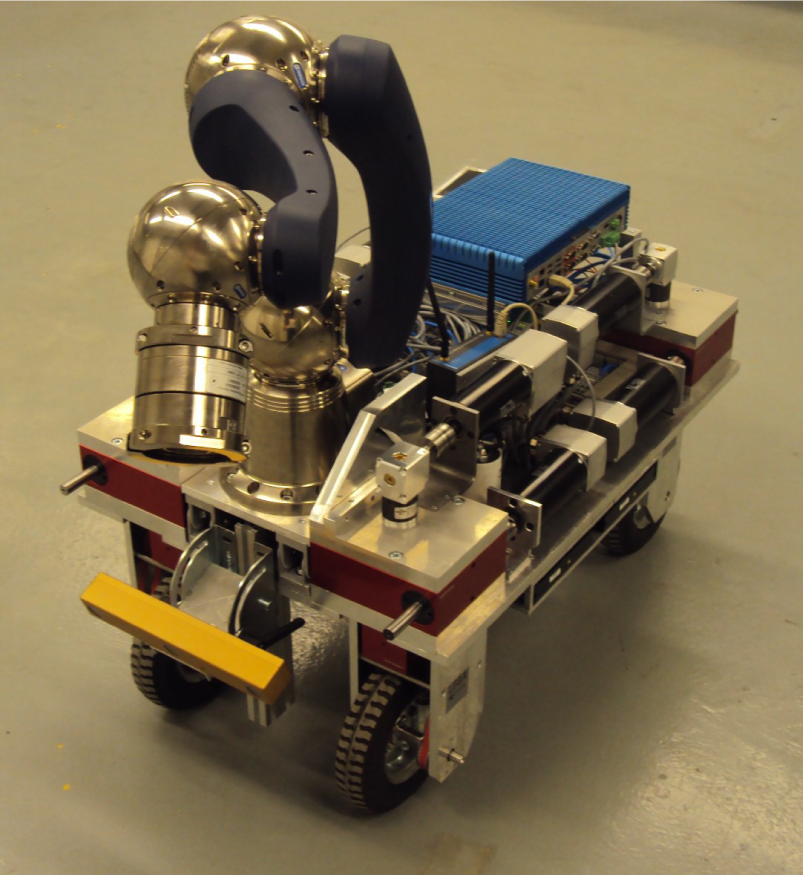
The four wheel steerable mobile manipulator (iMoro)
The contributions of this paper can be divided into higher-level strategies and lower-level practical issues for design improvements of a safety standards-compatible, fault-tolerant robot for SFs. This paper reflects the decomposition of a high-level mission to generate several commands and the structural behavior of the robot. Next, we describe the necessary modules for achieving the required functionalities of the robot. Moreover, to make the robot compatible with safety requirements, a safety anchor is proposed to provide a low-cost redundant decision-making unit. It maintains the robot's behavior during its mission as well as its exit in the case of unforeseen problems. The design considers the requirements for a robot tasked to explore the Large Hadron Collider (LHC) tunnels of the European Organization of Nuclear Research (CERN) as a sample SF.
Generally speaking, a cognition architecture can be divided into four control schemes: deliberative, reactive, hybrid and behavior-based [5];
Although all autonomous robots have to include deliberation [6, 7], a pure deliberative architecture cannot accomplish the requirements of contemporary applications [8]. In some cases, it is used in assisting the operator using autonomous functionalities, and in order to predict possible accidents [9]. A study conducted recently addressed several aspects of a deliberative control schema as a divide-and-conquer problem-solving strategy [7].
The hybrid control topology is developed to overcome the limitations of deliberative control and reactive control. It uses the reactive control scheme to respond to environmental changes and high-level planning to handle complex tasks [10, 11]. During this research, we partially apply a hybrid control topology for the architecture of a mobile platform. Moreover, the safety of the mobile manipulator is another issue addressed in this study via a service robot with a lightweight arm [12].
The aim of this paper is to determine a strategy for utilizing a mobile manipulator in inspections planning and scheduling [13] and interventions instead of human intervention [2]. In order to lower the risks, it is more reliable to control the behavior of the autonomous identification or model-based control process by a safe configuration [14]. We propose a redundant safety-compatible architecture to tolerate the faults of the main architecture. It contains a set of actions activated by pre-selected processes through triggers.
2. Problem definition
This paper represents an architecture for a Modular Mobile Manipulator System (MMMS) to be used as a road map for the design and implementation process of mobile robots targeting SFs. The concepts are designed based on the statement of needs and requirements as a part of the PURESAFE project systems engineering documents [4]. The project, “Preventing hUman intervention for incREased SAfety in inFrastructures Emitting ionizing radiation” (PURESAFE), has been initiated to advance theoretical and experimental knowledge regarding semi-autonomous mobile manipulation within the ionizing radiation and contaminated environment of accelerators, in particular the tunnels inside the CERN and the GSI Helmholtz Centre for Heavy Ion Research, Facility for Anti-proton and Ion Research (GSI/FAIR). While perception and navigation are challenging issues for mobile platforms, robot intervention in SFs and hazardous environment imply more significance of architecture design considering fault tolerance and safety in robot cognition.
Although a variety of requirements should be considered in the architecture design of the robot, we only discuss a sample solution to a task scenario described in 2.1. In addition to the challenging issues of mobile manipulator architectures, this research considers an important and mandatory constraint for the robot:
“As a service robot, the robot should not cause human intervention in the test environment. In case of failure in mission, it should be able to return to its station.”
This restriction affects the risk assessment results and highlights the immobility of the robot as the most severe failure of the robot. Moreover, the presence of the robot in the neighborhood of scientific test equipment during operation or maintenance time, arises failure severity even with a low occurrence chance. For instance, any damage to the experiment infrastructure results in a SF shutdown and human intervention in hazardous environment. The robot perception, planning and navigation should be safe and reliable so as to guarantee avoiding any destruction or unplanned shutdown in the SF and to ensure the robot's ability to escape from the test environment in an emergency. To overcome this problem, the proposed architecture design of the robot will be addressed in the following sections. We use
Similar to other complex systems, SFs are the subject of frequent inspections and maintenance during their life-times. Moreover, modifications, repairs and inspections have to be accomplished over a short duration to prevent the shutdown of scientific experiments, aging of the robot body, the effects of ionizing or non-ionizing contamination, and hardware corrosion. In the following section, we will define a sample mission for iMoro and describe the necessary hardware and software components in the rest of the paper that are compatible with the described constraints.
2.1 Task description
A mobile manipulator can have wide range of applications within SFs. In this section, to summarize the system description, the authors define a mission as a sequence of tasks to develop necessary hardware and software components. A sample inspection covers the following description:
Mission Receive commands on control room Human Machine Interface (HMI): In point “A”, Fast forward to section “B” addressed on the CAD-based map. Prepare for tele-operation around the device number “36” and then inform the operator for a semi-autonomous operation. Touch the object defined by the operator. Inspect the area defined by the operator and transmit preliminary results. Finally, come back to your station and give detailed data report.2
To task the robot mobile manipulator inside a hazardous area of a SF, there are several limitations and requirements. Some of the key requirements are listed below:
Requirement 1. The physical or chemical effects of materials and test equipment in the environment can affect the work performance and lifetime of electrical components.
Requirement 2. The facilities are mostly designed for humans, the test equipment or special machines accessible through different corridors. There is no dedicated environment or specific landmarks – or setups for a robot except its station. In other words, the environment is unstructured for a robot.
Requirement 3. A lack of communication can frequently occur. The robot shall be tolerant to failures of Wi-Fi or delays of GSM transmitted signals.
Requirement 4. The purpose of utilizing a robot is to prevent human intervention in hazardous environments. Therefore, during the operation of the robot, the area is not suitable for humans, and all robot operations shall be remotely controllable.
Requirement 5. In case of failure, the robot should be able to leave the SF.
Considering these requirements, the mission can break down into sequential tasks. Since, in most cases, the mobile manipulator applications are similar to the described mission, we describe here those tasks, while we describe the overall solution later on.
Task 1. Initialization
Get the global map
Task 2. Planning
Convert the global map into a 2D occupancy grid
Task 3. Autonomous Running Mode
Run these modules in parallel, repetitively:
Task 4. Update Mode
After reaching the target position, map the workspace on a detailed map. Extract the optimum features for accurate localization. Define the local stationary coordinate attached to the features. Obtain transformations between the new coordinate and the predefined coordinates. Upload the collected information to the supervisory room while considering possibility of data loss and a delay in connection. Finalize the autonomous mode and switch to the semi-autonomous mode. Call the operator through all of the available networks, such as Wi-Fi or GSM.
Task 5. Tele-operation Mode
Let the operator define the movements in the virtual environment and execute the commands in order. Update the current status for the operator by the minimal transmission of data to overcome any lack of connection bandwidth and to enable the possibility of augmented reality. In the case of selecting an object, run the visual servoing to approach the vicinity of the target object and do any inspection or manipulation as commanded by the operator. At the same time, maintain the prediction of power consumption. Set an alarm when the power reaches the limit of the safety margin. Quit from the position if the operator has finished the operation or else if the power limitation implies a forced return.
Task 6. Finalization Mode
Return to the nearest safe station. Set all the actuators to their home positions. Next, transmit all the gathered data by the high bandwidth connection, including the final status of the robot and its components and the evaluation of the modules that are gathered during run mode. Clear any temporary information. Recharge the embedded power source.
Task 7. Standby Mode
Turn off any high-consumption hardware and keep the control blocks in sleep mode. Wait for the next trigger and another mission.
According to the tasks and their descriptions, the rest of this paper gives an overview of the hardware and then describes the necessary software modules and the architecture designed for the concisely described tasks.
2.2 Sensors
The robot is equipped with several sensors to collect data from its components and the environment. We describe them in the following subsections.
2.2.1 Laser range finder
(LRF) The laser scanner or LRF provides a 2D map of the environment based on the reflection of its infrared beams. The output data comprise pairs of distance and angle based on a predefined polar coordinate attached to the {ℒℛℱ} coordinate. The origin of {ℒℛℱ} which is virtually defined as attached to the axis of rotation of its motor in such a way that the +z direction is collinear to the axis of rotation. Therefore, all the transmitted points rely on the x – y plane of {ℒℛℱ} The corresponding Cartesian representation of the detected point number k by the laser scanner can be defined as LRF Λ k (xKyK 0).
The number of detected points during one scan, max(k), depends on the field of view (FOV) and the angular resolution of the laser scanner. Note that the source of systematic and random errors in the positions of the detected points are still in the polar coordinate as errors in the distance and angle [15,16]. We can write for the vector of points:

The output of the laser scanner determines the position of the robot relative to its environment by a Simultaneous
Localization and Mapping Toolbox (SLAM) as described in Subsection 4.2. Moreover, its output can be a local map for obstacle avoidance and heading estimation.
Despite the fact that the LRF is a robust sensor for the navigation of the mobile platform, it fails in the detection of transparent and reflective materials in the environment [17]. It is also hard to detect darker materials at longer distances. Regarding these issues, the sensor can be considered as a safe sensor for short distances (under 20m). Besides the accurate distance angle measurements, it is possible to define warning zones on the same plane. In this case, the scanner transmits the corresponding situation of each zone. This communication can be safe and totally independent of the points measurements, and can be utilized in the safety anchor mechanism described in Section 5. The warning zones can be defined as relay outputs or logical switches on the hardwired network.
2.2.2 Wheel odometry
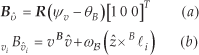
Each wheel of the robot is equipped by an encoder on the steering and driving servo motors. The measured values for the joint parameters used in the kinematics and then in the path-following controller are estimated based on these data. The steering actuators provide φ i as a feedback, and the driving actuators feed the driving speeds vi. These parameters have been used to determine the velocity vectors of each wheel as shown in Figure 2. The resultant data determine the robot's velocity v and angular velocity ω b and motion direction ψ v .
2.2.3 Current sensor
The overall current of the mobile manipulator passes through a current sensor. The measured sensor data can be used for the power consumption and then for the estimation of the remaining autonomy time. Moreover, it can sense any abnormal electrical loss during standby or the run-time of the robot. The energy management methods [3] are also applicable to analyze the information gathered from this sensor.
3. Kinematics
In this section, we present a kinematics formulation in the velocity space for the 4WS mobile platform. Although the equation is quite straightforward, it embeds substantial information pertinent to the relative velocities of the body and wheel modules. A general solution is then given for estimating the body's linear and angular velocity using kinematic constraints and encoders data. The solution uses the least squares method to measure the relative consistency of the legs' velocities, thus detecting faulty encoder data. The mobile robot can be fully functional even after losing the functionality of one of its wheel modules. Hence, this approach can be used to single out a faulty leg during the robot's operation.

Denoted kinematic parameters
3.1 Inverse kinematics
Figure 2 shows a schematic view of a 4WS mobile robot. The denoted parameters for the configuration of the body and the leg modules are presented in the figure. The coordinate frame U{X̂,Ŷ} is the inertial frame. Frame B{x̂, ŷ} is a fixed-body frame defining the heading of the robot, and Bv{v̂, û} is the velocity frame, that is, the unit vector v̂ determines the direction of the robot's base linear velocity vector. Both
in which, ẑ=[0 0 1]
T
and
3.2 Forward kinematics
As mentioned earlier, the speed of the drive actuators and the positions of the steering actuators are measured, that is, positions φ
i
for the steering actuators and speeds vi for the driving actuators. In this subsection, the goal is to derive ψ
v
,ω
B
and v based on the encoders' measurement data, that is, the sets {vi,φ
i
} for i = 1… 4. Clearly, the relative velocity of the wheel modules with respect to each other must be zero. In other words, the set {vi,φ
i
} applied to a leg should be consistent with other sets. Although the set points for the steering and drive commands are exactly with the kinematics relations due to different loads and different servo dynamics. Since the legs are connected to a rigid base, this inconsistency causes the legs to slip with respect to one another. This slippage is different than the overall slippage of the robot, and cannot be observed through odometry data. In order to measure the consistency of the actuators' actual values, we define the following measure:

where

In the above equations eij is the relative velocity line Li to Lj Clearly, if both wheels are synchronized perfectly and no slippage occurs, eij is zero. However, as explained before, in practice these variables are not zero and the value eij indicates the relative slippage of the wheel modules i and j. The variable ei is the measure of the relative slippage of one wheel with respect to the other three wheels. In practice, for the mobile robot to move properly, all ei s must be small. The value of ei s determine the overall consistency of wheel i with respect to the other modules. Several cases can be considered for different values of ei.
In the case where:

If ei is large only for one wheel, it can be interpreted such that the wheel is not consistent with the other wheels and that it is being pushed by them. In this case, different strategies can be considered, such as stopping the robot or singling out the faulty leg from the control loop and setting the actuators of the faulty wheel to rotate freely.
Alternatively, more complex strategies can be designed based on the robot's assigned task and application.
After calculating ei for all the legs and evaluating their values, the forward kinematics problem can be solved as follows. Let

in which

Obviously, in the general case the matrix Equation (6) consists of eight equations and three unknowns. A simple least squares solution is given by:

Note that the elements of A are the only function of the constant vectors
4. Robot software modules
4.1 Dead reckoning
Generally speaking, the time integration of the velocity vector – known as ‘deductive reckoning’ or Dead Reckoning (DR) – for a mobile platform gives its approximate position with respect to its initial pose [19, chap. 20]:


The driving velocities of the wheels as regards their steering angles and robot kinematics can generate fundamental data for the localization of the mobile platform.
4.2 SLAM
The errors for the mobile manipulator are accumulative during its motion. In order to reduce the errors, it is necessary to compare the position of the mobile base with respect to its environment. The SLAM [20] method provides the change in location of the robot according to its initial configuration. Moreover, it provides the local map of the environment
4.3 Path planning
The path-planning module comprises two modes: local and global planning. The planner initially plans the required path through requests from
The module also implements local planning. It receives the current status and some of the upcoming via points, together with the current local map
4.4 Path following
A path follower controller navigates the robot on the given path and returns the resultant pose. The path-following module considers actuator limitations at maximum velocity and acceleration [24-26]. The path follower also avoids obstacle on the robot's route.
4.5 Mobile manipulator controller
Manipulators are usually provided together with their specialized controllers. However, coordinated tasks have to be performed synchronously between the path follower for the mobile base and the arm controller [27]. We use a mobile manipulator controller to close the outer control loop that follows the task commands distributed among the mobile base and the arm in a similar manner to [28].

The robot's software and hardware modules
4.6 Fault management
Besides software fault detection and fault-tolerant techniques [29], it is necessary to monitor, verify and recover the robot's sensory data and actuator commands from the instrumentation and control viewpoint. This section contains a brief explanation of the fault management module's functionalities. As a general requirement for the fault tolerance of safety-critical systems [30, chap.1], the robot has redundancy in actuation and sensation. Four steerable wheels [31] reduce the risk of immobility caused by the mechanical hardware. The wheel odometry, IMU, laser scanner and camera provide redundancy for the perception of the robot. The fault management module's job includes:
Monitoring the input and output of the other modules. In the case of a single point failure of a module, using an alternative function. Verifying the consistency of the resultant sensory information from the different sources, for each sensor as well as results of sensor fusion:
where S1 and S2 are the localization or detection data from Sources 1 and 2, respectively. For a perfect system, AT becomes the identity 4×4 matrix. It should be noted that the inverse of a transformation matrix is calculated by the transpose of its rotational part as addressed in [28], Therefore, this calculation cannot be singular. Arguments of ΔT represent the inconsistency of the gathered information. If ΔT –I4×4 gives a sensible difference, the module learns the difference. In case of a change in the learned difference, it calls the calibration maintenance module which in turn calibrates the divergent sensor. In case of unacceptable divergence of the primary navigation sensors, the module suspends the motion of the robot and reports its status. Following the confirmation of the operator, the control changes to tele-operation mode.

The loop for the synchronization of the mobile manipulation tasks
Some errors can be solved by outlier detection and the substitution of the fused values. For instance, in the following we describe how, at each segment of the path, the module compensates for small errors between the position and velocity feedback of the wheels.
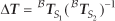
The localization is obtained by dead-reckoning of the odometry data as described in the previous section. The iMoro mobile platform shown in Figure 1 is used to run the experiments. The desired path that is followed by the mobile platform is a cubic Bezier curve with its control points located at {(0, 0), (2m, 0), (2m, 2m), (0, 2m)}. The path is used with two desired heading profiles. Figure 5 shows the body and legs trajectories for following the path with 180° rotation of the main body. Moreover, Figure 6 shows the same trajectories, this time for −90° rotation of the body. Figure 5 also depicts the estimated location of the body's Instantenous Center of Rotation (ICR) during its movement as red dots.

Experimental results: the robot's trajectories, 180° rotation
Experimental results: the robot's trajectories, −90° rotation

Experimental results: Least squares error before and after the elimination of the outlier leg

Experimental results: leg number for the most inconsistent leg
The forward kinematics solution is solved both with and without eliminating the leg with maximum ei Figure 7 depicts the pseudo-inverse error before and after the elimination. From the figure, it is clear that the error is reduced considerably by eliminating the leg with maximum ei from the forward kinematics solution.
Figure 8 shows the sensor number with the biggest ei at each sample time. From the figure, it is clear that, at each period, a different leg has maximum ei. This is due to the change in the dynamic loads acting on each leg during movement. Having one specific leg with maximum ei all the time could indicate a defect in that leg.
5. Safety Anchor (SA)
It is a key requirement for a robot in SFs to be safe or at least compatible with the safety standards' requirements. The first solution is to make the whole system certified by the safety integrated standards, for instance, the Safety Integrity Level (SIL) II or SIL in standards. The solution is suitable for mechatronic systems with lower flexibility and mass-produced products due to its complexity and cost. On the other hand, the perception and navigation of the mobile platform include a variety of procedures and instruments which are not necessarily safe. For the software, certain test techniques exist for the verification of the safety standards' compatibility. However, there are many issues confronting the verification of decision-making for an autonomous robot, even for industrial controlled environments, if we assume that the robots are Automated Guided Vehicles (AGVs). Moreover, the compatibility of the processes and the required modules for decision-making cause an increase in the robot's production costs and verification complexity. Furthermore, the robot must be equipped with safe instruments and safe process units, which is impossible for several sensors. For instance, vision-based estimations and acceleration measurements are not compatible with the current safety regulations.
In order to make the system tolerant to faults in these modules, we define a redundant controller. The controller is supposed to be safety compatible for both the hardware and software. The software must be reactive and simple, and therefore easy to examine. The hardware requirement for such software becomes suitable for implementation on a safe Programmable Logical Controller (PLC) or any other safe process unit. It should be noted that target application for this design comprises tunnels and corridor-shaped SFs. Locally, the watchdog on the robot, and remotely, the operator, can trigger the SA when the functionality of the robot is not as expected.
5.1 Hardware architecture
A schematic hardware architecture of the mobile platform is shown in Figure 9. The sensors and actuators are connected to the embedded PC, which runs all of the necessary cognition subsystems. The embedded PC is connected to the motor drives, arm joints, laser scanners, cameras, IMU and encoders. Most of the robot sensors provide the perception of the robot and its environment for object manipulation. The embedded PC is the target of the remote development method described in [32] during its run-time and debugging and the development of its algorithms. It should be noted that any failure in the embedded PC during its run-time can cause the immobility of the robot or a collision with other facilities in the environment.
In order to avoid failure, the authors propose adding a safety anchor topology as a redundant decision-maker for the mobile platform, as shown in Figure 9. During the robot's run-time, in case of any embedded PC failure, the safety PLC can be triggered by the watchdog or supervisory system to manage the mobile platform in escape mode by a reactive controller. Ignoring complex mathematical procedures and high-level algorithms, the PLC solves the navigation problem at the lowest possible level to guide the robot to safe places [33] before the operation of the accelerators. The redundant system can benefit from off-the-shelf, safe and certified components to guaranty the safety of the system.
The LRF sensors provide for the availability or occupancy of any predefined zone by toggling the corresponding signal. The signal goes through the logical circuits of the PLC. By limited conditional statements programmed on the PLC, the system reacts by commanding the motor drives in real-time. Since the logic, codes and connections are reactive, time-invariant and simple, their verification is easier and more dependable. In the same architecture, we can also program and utilize the embedded PC by means of the remote development method described in [32, 34].

The hardware architecture related to cognition; the yellow parts are the proposed safe components
5.2 SA logic
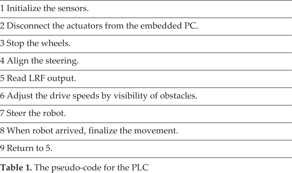
The hardware described in 5.1 needs a special setup, adjustment and programming. The LRF zones need the warning and alarm zones to be set up similar to the zones shown in Figures 10, 11 and 12. The reason for using the LRFs is their flexibility in the definition of sensitive zones and their compatibility with the safety standards. Generally speaking, the pseudo-code for the PLC can show the reactions between the sensors and actuators in Table
The pseudo-code for the PLC

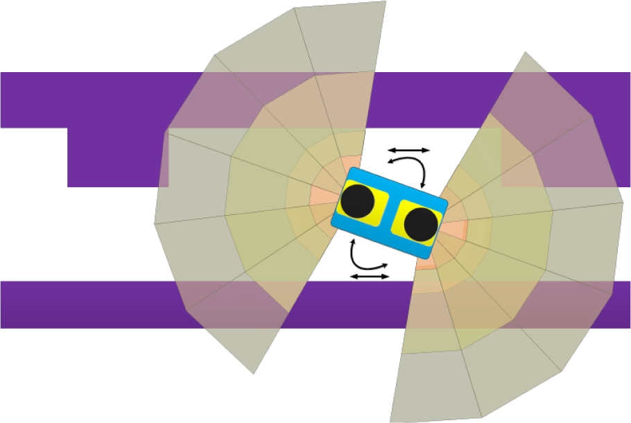
LRF zones, crab steering
LRF zones, robot spins around

LRF zones, cross movements
Furthermore, in the solution, we consider the conditions in SFs. For instance, it is common that the experiment infrastructures are located at one side of a tunnel or a corridor – as they are at CERN LHC or GSI/FAIR – and the transportation corridor usually runs along beside them in parallel or circular patterns. Therefore, within the path-selection routines, we give higher priority to following the simpler wall of the corridor. According to Table 1, let us divide the navigation into two parts: the determination of the robot's velocity (driving), and steering. In the upcoming paragraphs, we describe the overall idea and the benefits of a 4WS mobile robot for this purpose.
The robot's steering capabilities, as described in Section 3, include a vast area of selection and calculation so as to determine it for each wheel of the robot [24, 35]. However, a robust solution, a dependable implementation and a reliable verification method for such calculations become complicated, especially if a safe solution is required. Recall that the robot's immobility is a high-severity failure. For the purpose of simplification, we assume that the robot has only two types of steering: crab steering and spin around to keep the detection [36], planning [37], kinematics, and control [26] simpler than contemporary solutions.
5.2.1 Crab steering
Crab steering means that the angular velocity ω
B
shown in Figure 2 and mentioned in (2b), becomes approximately zero. Fn other words, the instantaneous center of rotation (ICR) goes to infinity. As such, (2b) becomes:

This means that the velocity vectors of the body and legs become parallel (or equal) to each other. In such a case, it is not necessary to solve the system of kinematic equations of the robot and the direction of Bv^; body's velocity vector defines the wheels' steering angles Bv^i. Any change in the steering comes from the change in the body's movement direction (not the heading). In this case, the robot can continue with high-speed linear motion up to a sensible change in the velocity direction regarding the actuator limitations.
Crab steering activates when the robot is approximately parallel to the simpler wall of the corridor while the robot has obstacle in front as shown in Figure 10. The crab steering maintains the distance from the side obstacles or walls without lowering speed. The magnitude of velocity vector v is proportional to the proximity of the obstacles in front of the vehicle. It should be noted that, instead of a distance measurement, a corresponding number for the zone is considered.
5.2.2 Spin around
There exists another method which leads to a significant simplification of the complicated path-follower kinematics. The 4WS robot can turn around on the spot without any linear movement, or negligible translational movements. In this case, the ICR converges into the centroid of the robot. In this case, another term of the velocity analysis becomes zero. The kinematics relations in (2b) become:

which shows the constant angles of the wheels perpendicular to
6. Conclusion
In this paper, we study the architecture of a mobile platform. The overall architecture, including a variety of software modules, is studied in detail, and is suitable for risk assessment and RAMS analysis. Moreover, a top-down strategy is described to show how a high-level mission can be broken down into several tasks as well as which hardware/software are required to accomplish the mission. In order to consider safety concerns in Scientific Facilities (SFs), we propose “Safety Anchor”, a redundant decision-making system that can ensure that the robot leaves any hazardous environment without the presented cognition architecture. Moreover, Safety Anchor guarantees meeting the challenging limitations of the actuators by solving the kinematics of the robot in its simplified form. The specifications and design requirements of a four wheel steerable mobile manipulator, the IHA Mobile Robot (iMoro), are considered as a case study in this paper.
Footnotes
2
The numbers and names here are only samples for non-quantitative addresses by the operator.
3
It should be noted that
7. Acknowledgements
This work, supported by the European Union's Seventh Framework Program under the Marie Curie Initial Training Network, was carried out within the framework of the PURESAFE, Preventing hllman intervention for incREased SAfety in infrastructures Emitting ionizing radiation, under RE A grant agreement number 264336.