
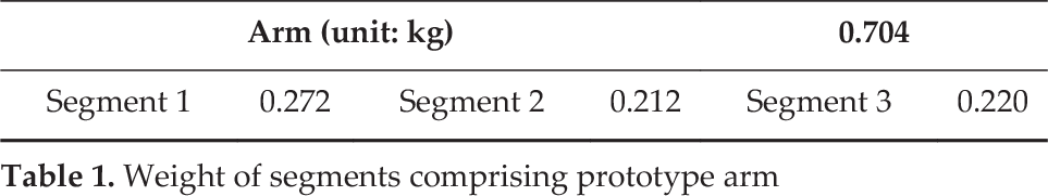
Abstract
Transhumeral and shoulder disarticulation amputees find it difficult to move their prostheses for goal-oriented movement using only their small residual limbs. Thus, spatial accessibility is especially important for shoulder prostheses. Moreover, because responding to external disturbances and absorbing impact using only the viscoelasticity and flexibility of the small residual limb is difficult, the intrinsic viscoelasticity of the shoulder prosthesis is indispensable for safety. In our previous work, we proposed a small pneumatic elastic actuator-driven parallel link mechanism for shoulder prostheses. In this paper, we propose two new devices, a sliding antagonistic mechanism and a soft backbone, to improve the spatial characteristics and disturbance responsiveness. We quantitatively evaluated a prosthetic arm with the two devices. The results showed that the two devices increased the arm's workspace and disturbance responsiveness.
1. Introduction
Upper limb prostheses can be used by amputees to substitute lost motor-sensory functions. Compared with wrist disarticulation and below-elbow (transradial) amputation, prostheses for shoulder disarticulation and transhumeral amputation need much more research. In this paper, we call the prosthesis for transhumeral and shoulder disarticulation level amputation a shoulder prosthesis for simplicity. Such prostheses are also beset with more problems; for example, transhumeral and shoulder disarticulation amputees find it difficult to move their prosthesis for goal-oriented movement using only their small residual limb. Thus, spatial accessibility is especially important for shoulder prostheses. Moreover, because responding to external disturbances and absorbing impact using only the viscoelasticity and flexibility of the small residual limb is difficult, the intrinsic viscoelasticity of the shoulder prosthesis is indispensable for safety.
In our previous study, we proposed a small pneumatic elastic actuator-driven parallel link mechanism for shoulder prostheses. The manipulability and accessibility of the prosthetic arm were defined, and the arm configuration was optimized [1]. However, the spatial characteristic of the optimized configuration was not satisfactory; in particular, the workspace of the arm was insufficient for ordinary activities of daily living (ADLs). Moreover, responses to the load applied to the end-effector were not confirmed. More importantly, safety issues with the intrinsic viscoelasticity such as the disturbance responsiveness—specifically, responsiveness against collision from external impact—have not been investigated.
Only a few studies on the spatial characteristics of shoulder prostheses have been reported. In a related study, a serial link arm where the number of degrees of freedom and a combination of the active rotational joint with a motor and passive rotational joint were set as parameters, the reachable workspace and practicability of some ADL trajectories were evaluated [2]. To improve the spatial characteristics, we previously employed a biasing spacer to adjust the actuator layout and optimize the adjustment length; we proposed a method of tuning the workspace of the whole arm [3]. The mounting angle of the segments making up the arm was set as the parameters, and the design procedure for a shoulder prosthesis that is more viable for daily living was constructed by evaluating the actuator's required force statically in addition to existing spatial characteristics [4]. Other studies reported the development of devices that improved the spatial characteristics, although they did not directly deal with the spatial characteristics of prostheses. Examples include a ball joint mechanism called a partially opened joint that widens the range of motion of a humanlike shoulder complex for musculoskeletal robot arms [5] and a mechanism to lengthen the actuator stroke of rehabilitation devices [6].
A high level of flexibility has advantages with regard to collision responsiveness. This can be achieved by having the device comply with impedance control based on sensor information; the interaction control approach has been studied [7]. However, flexibility requires not only a control method but also a mechanically passive component that is embedded in the mechanism [8]. This will mitigate the colliding force without producing a time delay, even if the mechanism collides against unpredicted objects. Some studies have employed this flexibility of the mechanically passive component to develop robot hands, manipulators, and medical devices that can be applied to shoulder prostheses [9]. For example, a device has been built that uses a nonlinear spring as the mechanical passive element, where controlling the tension of the wire adjusts the flexibility of the joint [10]. Other devices have been developed where the stiffness is changed by inserting a disk into a coiled spring or by adjusting the viscoelasticity with a leaf spring [11, 12]. To achieve a safe damping force, some studies have used a magnetorheological (MR) damper rather than a spring [13]. An MR damper uses MR fluid to change the viscosity in a reversible fashion with a magnetic field.
Some studies have used pneumatic elastic actuators [14, 15], although they did not directly consider prosthetic arms. This actuator possesses flexibility because of the viscoelasticity of the air and elastic. Therefore, preparing the input and passive element separately is not necessary, which reduces the weight and volume. Note, reducing the volume influences the shape of the prosthesis, which is a very important design factor. Considering the properties required of the prosthesis, a pneumatic elastic actuator with light weight and high output power and viscoelasticity is suitable. Shape memory alloys (SMA) have similar properties to actuators. An anthropomorphic prosthesis was developed using SMA [16]. However, SMA is generally inferior to other actuators with regard to responsiveness; and, the prosthesis in [16] was for the hand, not the arm.
In this study, we first developed a prototype arm using a pneumatic elastic actuator as a basic mechanism to serve as the benchmark. Two devices were proposed to enhance the spatial characteristics—i.e., workspace—and mounted onto the benchmark arm. Various arm configurations using different combinations of these devices were tested by loading the end of the arm and compared. Based on a careful consideration of the safety— specifically, disturbance and collision responsiveness— the optimal configuration of the shoulder prosthesis was determined. Safety was improved by using the natural mechanical viscoelasticity; improving the control aspect is a future objective.
2. Arm mechanism
2.1 Overview
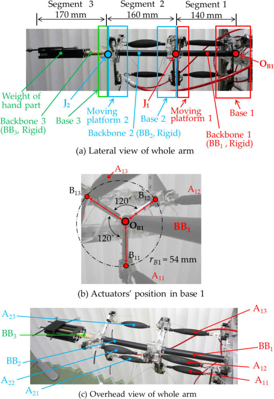
Figure 1 shows the prototype arm for the benchmark. The arm comprises three segments, and each segment is connected to the next one in the series. Segment 1 links two parts, namely base 1 and moving platform 1 with backbone 1 (BB1) as a support rod and three pneumatic actuators (A11, A12, A13) that are evenly arranged centring around the backbone (Figure 1(b)). Thus, this segment has a parallel link mechanism. The backbone is made of polyacetal and assumed to be a rigid body. Backbone 1 is set at the centre of base 1 (OB1) and connected to the centre of moving platform 1 (OM1)by a ball joint (J1). This enables moving platform 1 to turn joint J1 between moving platform 1 and backbone 1 by activating the actuators. Segment 2 has the same structure as segment 1 except for the backbone's length. Segment 3 is presumed to comprise a robotic hand; however, the hand has not been developed yet. Therefore, the experiments were conducted with a weight corresponding to the hand at its position, as shown in Figure 1(a). The dimensions of the segments are shown in Figure 1. The connection points of the actuators to bases 1 and 2 are located at radii rB1,2 = 54 mm from the base centre OB1, 2. Those to moving platforms 1 and 2 are located at radii rM1, 2 = 49 mm from centre OM1, 2. When determining the geometry of the arm, the targeted ADL motions should be considered. We think that all the ADLs, such as eating, toileting, bathing, dressing, and personal hygiene are important. However, current engineering technology, including prosthetic technology, is not sufficient to produce a prosthetic arm for all the ADLs. After carefully checking the ADLs, we found that the hand-to-face-or-mouth motions, which are involved in eating, part of dressing, personal hygiene, are most important. Therefore, in this paper we defined these hand-to-face-or-mouth motions as the intended ADL motions of our prototype arm. Moreover, in our previous study [4], we measured these ADL motions, in particular, eating from a lunch box, drinking a bottle of water, brushing teeth, and putting on socks by using a motion-tracking system (OptiTrack); the user's target area was set up based on the actual motion range of a hand from the ADL data. For optimization, the accessibility and manipulability of the arm in the target area were set as evaluation indices, and the arm dimensions were set as design variables [1, 3–4]. The results were used as a reference to determine the dimensions of this arm in this paper. Table 1 gives the weight of the prototype.
2.2 New devices
In our previous studies, we proposed methods to align actuators by using biasing spacers inserted into the actuator [3] and to adjust the mounting angle of segments [4] to enlarge the workspace of the arm. In this study, we performed experiments to evaluate the new methods of sliding the actuator and changing the material of the backbone in the benchmark prototype for further refinement.
2.2.1 Kinematics models
First, the kinematics model of the mechanical structure of the arm is presented to facilitate comprehension and explain the new devices. The coordinate system of the arm is shown in Figure 2. The global coordinate system OB1-x1y1z1 is set to the centre of base 1 with the z1-axis directed along backbone 1. The local coordinate systems OB2-x2y2z2 and OB3-x3y
3
z3 are placed at the centres of bases 2 and 3, respectively. Ball joints J1 and J2 in Figure 1 are situated at the connection points between segments OB2 and OB3, respectively. As described in Section 2.1, the installation points of the pneumatic actuators to the base and moving platform are B1i, B2i and M1i, M2i (i = 1, 2, 3); these are set up at equal angles along the peripheries of circles with radii rBj and rMj (j = 1, 2), as shown in Figures 1 and 2. Bj1 and Mj1 are each in the local xj-axis direction (j = 1, 2). Backbone 3 is placed at OB3 along the z3-axis. The lengths of the pneumatic actuator
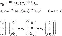
When radii rBj and rMj are fixed (i.e., in the benchmark configuration), activating the actuators as shown in Figure 2(b) causes their lengths to change; a1i and a2i become a1i′ and a2i′ (i = 1, 2, 3). Therefore, M1i, B2i, and M2i (i = 1, 2, 3) are forced to move to M1i′, B2i′, and M2i′. Two passive ball joints (joint J1 between segments 1 and 2 and joint J2 between segments 2 and 3) rotate by θ
xi
, θ
yi
, and θ
zi
(i = 1, 2), respectively. Let the rotation matrix of J1 and J2 be Rθ1 and Rθ2. In addition, let the coordinate of the hand position, i.e., backbone 3′s end tip, be
Prototype
Weight of segments comprising prototype arm
2.2.2 Sliding antagonistic mechanism
A small slider is set up at each point connecting the actuator to the base and the moving platform of the segment: B1i, B2i, M1i, and M2i. The details are given in Figure 2(c) and 3. When a certain actuator is activated and shortens, other actuators mutually interfering with it around a symmetrical axis, i.e., the backbone, are pulled. Therefore, the maximum length of these actuators prevents the joint of the arm from rotating further, as shown in Figure 3(b). However, the slider mounted at the base of each actuator passively slides to the backbone up to 31 mm on its rail, which links the centre of each base or moving platform to the contact points B1i, B2i and M1i, M2i, as shown in Figures 3(c)–(e). Therefore, the actuator also slides in a similar manner. This enables the joint of the segment to rotate further, as shown in Figures 2(a) and (c) and 3(b) and (c). This motion is due to the small angle α (set to 8° in this study) with which the slider and its rail are mounted to the base or platform: in other words, the angle against the x-y plane, as shown in Figure 3(d). Hence, the rotational angle can be increased, and the workspace of the arm can be enlarged. When the activated actuator returns to normal, the slider is forced to return to the initial position by a spring mounted between the slider and Bij or Mij.

Kinematics models
When the sliders are attached to the benchmark configuration, they passively move when the actuators are activated, as shown in Figure 2(c). Their increments are given by dB1i, d
M
1i, dB2i, and dM2i (i = 1, 2, 3). Therefore, assuming that the symbols are the same as in (1), the relational expression between a1i′, a2i′ (i = 1, 2, 3), and 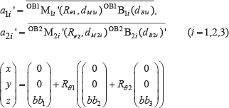

Details of two devices
2.2.3 Changing material of backbone: soft backbone
As described in Section 2.1 a rigid rod was used as the backbone of the benchmark arm In this study we proposed the use of a soft backbone (i.e., elastic) as a substitute for the rigid one We performed experiments to confirm whether the elastic backbone could enlarge the workspace of the arm and impair the payload compared to the rigid one Elastic material has the potential to contribute to the collision responsiveness; details are explained later Two different kinds of backbones were prepared for the experiments: a traditional rigid one and an elastic one The specifications of the two backbones are as follows Both diameters were ϕ15.0 mm; the lengths were keyed to each segment.
Rigid (polyacetal, in Figure 1(a))
Elastic (polyether urethane rubber: Shore A hardness of 95 (ISO 868), in Figure 3(g))
3. Motion experiments
We conducted motion experiments to investigate the workspace, the effect of the load applied to the end tip, and the collision responsiveness, i.e., the viscoelasticity of the arm. The viability of the devices in Section 2.2 was confirmed. To validate the new devices, configurations that combined the slider's presence or absence with the backbone's two materials were set up as shown in Table 2. Only No. 5 HYB (hybrid) used backbones with two materials: rigid for segment 1 and elastic for segment 2. In HYB, segment 1 was rigid because it was placed at the base of the arm and thus subjected to more external force than segment 2. Table 2 presents the initial minimum pressure on the upper two actuators of segment 1 (A12 and A13 in Figure 1(c)) to maintain the arm as horizontally straight. Figure 2(a) shows the initial state of the actuator.
3.1 Workspace and effect of load
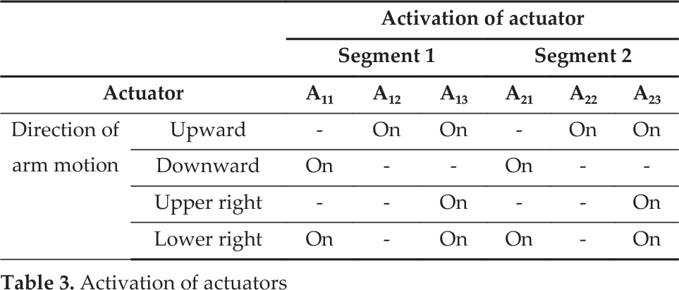
The workspace and effect of the load on the arm were confirmed by the motion experiments. Configuration Nos. 1–5 in Table 2 were used to validate the effectiveness of the devices. First, the workspace was measured without any load when the arm was moved in the upward, downward, upper right, and lower right directions by actuators, as shown in Table 3. In particular, the travel distance of the end tip dTr from the initial state to when the actuators were activated was measured, as shown in Figures 3(b), (c), and (f). Next, dTr was measured with loads of 0.1–0.4 kg in the upward and downward directions.
Configurations of arm

Activation of actuators
3.2 Viscoelasticity measurement
3.2.1 Spring constant
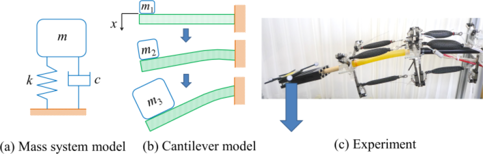
To investigate the characteristics of the arm's collision responsiveness, we measured the spring constant k and viscous damping coefficient c. We considered the arm using the simplified model of a mass system and cantilever, as shown in Figure 4. To examine the spring constant, a static load F (mass m) of 0.05–0.5 kg was added at the end tip of the arm in increments of 0.05 kg. The displacement of the end tip x was measured, and k was confirmed. This measurement was repeated 10 times for all 11 configurations given in Table 2. Configuration No. 6 is the benchmark No. 1 RGD but upside-down, and its initial pressure in Table 2 is for A11, as shown in Figures 1(c) and 5. In configuration Nos. 7–11, the initial pressures were gradually added to No. 1. The effect of the devices was confirmed by comparing No. 1 with Nos. 2–5. The effect of the pneumatic elastic actuator was investigated by comparing No. 1 with Nos. 7–11. The effect of the load in different directions was investigated by comparing Nos. 1 and 6. These measurements were conducted with a motion capture system. Spring constant k was derived from (3).
Measurements of k with static load F

Configuration No. 6

3.2.2 Viscous damping coefficient
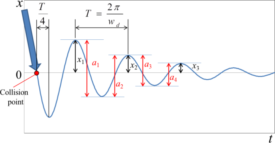
To measure the viscous damping coefficient c of the arm, an experimental system was set up, as shown in Figure 6. First, a free-falling weight of 0.1 kg was collided with the end tip of the arm from a height of 40 cm, as shown in Figure 6. The behaviour of the end tip was measured by the motion-tracking system. Because adhesives were set at the end tip and weight, they adhered to each other and showed the same behaviour after collision. Their trajectory was basically as expected, as shown in Figure 7. This measurement was repeated 10 times for all 11 configurations in Table 2. Their oscillatory waveform is represented by (4) and is shown in Figure 7 [17]. The displacement, natural angular frequency, damped angular frequency, damping ratio, time, and arbitrary constant are denoted by x, wn, wd ζ, t, and C1 respectively.
In Figure 7, the vibration amplitudes are x1 x2, x3,… xi; thus, the amplitude ratio after cycle T is shown by (5). Generally, the amplitude ratio after iT is x1/xi; the logarithmic decrement δ, damping ratio ζ, and viscous damping coefficient c are defined in (6)–(8), respectively [17].

Measurements of oscillatory waveform in collision experiment

Example of experimental damped oscillatory waveform


Because the equilibrium position of the measured oscillatory waveform was difficult to read, a i was read as shown in Figure 7; (6) was doubled to become the logarithmic decrement δ, as shown in (9).

The ζ and c values were obtained from (7) and (8); the natural angular frequency wn, damped angular frequency wd, and cycle T were calculated using (10), (11), and (12), respectively. These values were used to identify C1 in (4). Therefore, (4) could be determined. Thus, the ideal oscillatory waveform can be approximated, as shown in Figure 8. This ideal waveform was used to compare the behaviours of all 11 configurations.


Approximated ideal oscillatory waveform
3.3 Absorption of impact force
Let the velocity of weight m immediately prior to collision with the end tip of the arm be v, the velocity shortly after collision be v′, and the time from collision to when the end tip of the arm stops at the lowest point (v′ = 0) be dt. Using the change in momentum, the impact force FIm can be expressed as shown in (13) [18]. FIm was calculated for all configurations, and the difference in impact force was confirmed. Here, let dt be T/4 by using (12), as shown in Figure 8. The free fall is given by (14). The value of v was calculated to be 2.8 m/s by using h = 0.4 m (see Figure 6) and g = 9.8 m/s2.


4. Results
4.1 Effect of slider on workspace
To confirm the effect of the slider device on the workspace of the arm, we measured the travel distance of the end tips dTr from the initial state when the actuators were activated without any load, as shown in Figures 3(b) and (c) and Table 3. Figure 9(a) compares configurations RGD and SLD. SLD showed improved dTr against the benchmark RGD in all directions (upward, downward, upper right, and lower right); thus, the effect of the slider was confirmed. The effects in the upward and lower right directions were especially large. This is because the slider displacement in these two directions was projected in the direction of the end tip motion and thus was geometrically longer. In these two directions, dTr increased by 105.8% on average in the simulation with (1) and (2); it increased 89.8% on average (standard deviation: 13.1%) in the experiment.
4.2 Effect of elastic backbone on workspace
To investigate the effect of the elastic backbone on the workspace of the arm, we conducted the same experiment presented in Section 4.1. Figure 9(b) compares configurations RGD and ELS. Because the elastic backbone was unable to support the arm's own weight, ELS could not improve dTr relative to RGD with the rigid backbone in the upward direction; it extended in the downward direction owing to the arm being weighed down.
4.3 Effect of the slider on the workspace with load
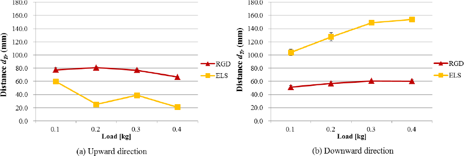
We measured the travel distance dTr in the upward and downward directions with loads of 0.1–0.4 kg. Figure 10 compares configurations RGD and SLD. Basically, SLD was more affected by the load compared to RGD. However, SLD was still confirmed to have an advantage with regard to the workspace.
4.4 Effect of elastic backbone on workspace with load
We conducted the same experiment presented in Section 4.3 for configurations RGD and ELS, which are compared in Figure 11. Similar to the results discussed in Section 4.2, ELS underperformed RGD with regard to dTr in the upward direction. In turn, it extended in the downward direction.
4.5 Effect of combining slider and elastic backbone on workspace with load
We conducted the same experiment presented in Section 4.4 for configurations Nos. 1–5 in Table 2, which are compared in Figure 12. No. 4 ELS+SLD (purple line) combined the slider with an elastic backbone; it was unable to enlarge the distance and support a load of 0.4 kg because the slider was dragged by the strongly bent backbone. No. 5 HYB (green line) combined the slider with elastic and rigid backbones and could support a load of 0.4 kg; the distance in the upward and downward directions was improved compared to RGD.

Comparison of configurations in workspace

Comparison of configurations RGD and SLD in workspace with load
Comparison of configurations RGD and ELS in workspace with load

Comparison of configurations RGD, SLD, ELS, ELS+SLD, and HYB in workspace with load
4.6 Measurement of spring constant
Figure 13 shows the relationship for all configurations between the displacement of the arm's end tip x and static load F (mass m), which was 0.05–0.5 kg added at the end tip in increments of 0.05 kg. Nos. 1–5 are shown in Figure 13(a), and Nos. 1 and 6–11 are shown in Figure 13(b). The spring constant k was calculated from the data by using (3) and the least-squares method, as shown in Figure 14.

Relationship between the displacement and load for all configurations

Spring constant k for all configurations
4.7 Measurement of damping ratio and viscous damping coefficient
The damping ratio ζ and viscous damping coefficient c were derived by using the spring constant k acquired in Section 4.6. Raw data of the oscillatory waveform were obtained from the collision experiment and the method described in Section 3.2.2, as shown in Figures 15 and 16.
Figure 17 shows the ideal oscillatory waveforms that were approximated by using (4).
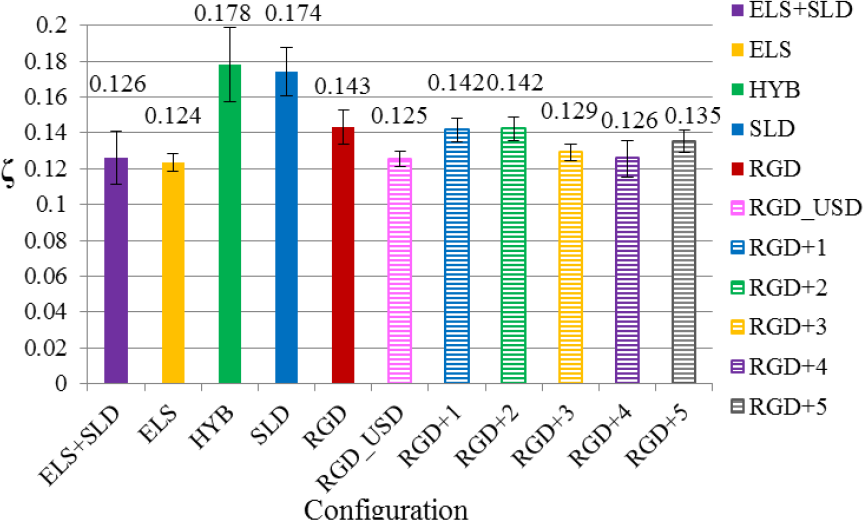
Damping ratio ζ for all configurations
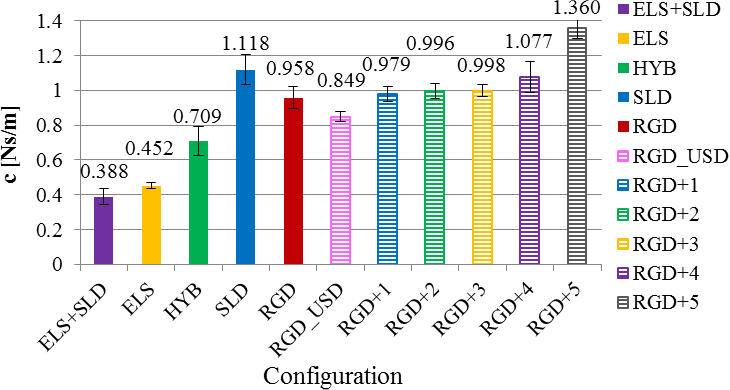
Viscous damping coefficient c for all configurations

Approximated ideal oscillatory waveforms for all configurations
4.8 Calculation of impact force
Impact force FIm was calculated with cycle T by using the coefficients acquired from (12) and (13). The results are shown in Figure 18.

Impact force FIm and cycle T for all configurations
5. Discussion
In the experiments, the devices were embedded into the arm of the basic configuration (i.e., benchmark No. 1 RGD) to evaluate their potential to enhance the workspace with regard to the load and collision responsiveness.
First, the workspace with the load was verified. The slider device improved the distance dTr (i.e., workspace) of the SLD in all directions compared with RGD, as shown in Figure 9(a). Figure 10 shows that the superiority of SLD remained even when the load was increased. Therefore, the SLD was considered superior for both the workspace and payload, which are generally in a trade-off relationship. In this study, although the behaviour of the prototype arm in the ADL motion was not directly examined in this paper, we aimed to fulfil part of the important specification required by the ADL motions, establishing the mechanism to realize the specification, further measuring and analysing the fundamental properties of the mechanism. The ADL test which requires not only mechanical design and measurement, but also path planning, the control of the nonlinear pneumatic actuators, and an interface for subjects, would be addressed in a following project. Regarding dTr, in our previous analysis of the drinking motion with one subject who is 170.5 cm tall, the required angle of the elbow was about 120° in reference [19]. Let the length from the elbow to hand be 330 cm, the dTr in that case corresponds to 571.6 cm whereas the length of SLD with a load of 0.1 kg was nearly 150 cm in Figure 10(a). Therefore, although the dTr of SLD is improved comparing the RGD (benchmark config. without slider), the workspace with a slider device of the SLD arm in this paper is considered to be not yet enough compared to the human arm in an actual ADL motion. However, considering that, this value is achieved by only pneumatic actuators with lightweight, softness but a short stroke, it is not so difficult to understand. Moreover in our previous study [4], a biased or active base segment could satisfy the workspace requirement of the hand-to-mouth motion.
Regarding the role of the slider, as shown in Figure 10(a), the larger the load was, the shorter the dTr was. Thus, it is possible that the load-dTr graph of SLD (with slider) approaches that of the RGD (benchmark config. without slider) as the load increases in Figure 10, and gets worse if the load becomes more than 0.4 kg due to the intolerability of the spring of the slider in Figure 3. Therefore, although we showed that the slider device could improve the workspace property, the mechanism should be designed based on the expected workload, by changing the spring constant, the parameter of sliders. In particular, the tension spring of the slider, as shown in Figure 3(b) and (c), has a large effect on the workload, therefore changing the slider's stiffness with different springs could achieve a different workloading gain.
The elastic backbone was found to be unable to maintain the arm posture owing to its softness and self-weight. Thus, ELS could not improve the workspace with and without the load compared to RGD, as shown in Figures 9(b), 11, and 12. On the basis of these results, the elastic backbone was not found to be effective for this index.
HYB showed better results than RGD when the load was increased, as shown in Figure 12. Compared with SLD, HYB did not show a large difference in the upward motion but did so in the downward motion. This was because of the sagging elastic backbone of segment 2 (see Figure 1 and Table 2). The dTr value of HYB in the upward direction was better compared with that of ELS because of the usage of half the number of elastic backbones. Thus, this elastic backbone can be useful when its length is adjusted. The configuration with the elastic backbone can increase dTr in the gravity's direction; in other words, the workspace can be increased in the direction of the applied external force.
Next, the configurations were compared for their collision responsiveness. The results showed that the spring constant k was slightly smaller for SLD than for RGD, but the difference was not large. This means that the slider could maintain its position despite the load. SLD had a larger dTr than RGD in the upward motion against gravity, as shown in Figure 12(a). This can be explained by the measurement results of the experiment on the spring constant. The presence of the elastic backbone greatly influenced the spring constant; ELS+SLD, ELS, and HYB had a very small k compared with the other configurations, as shown in Figure 14.
When the initial air pressure of the actuator for RGD was added, i.e., RGD+i (i = 1…5), k was confirmed to change quadratically, as shown in Figure 14. Thus, the property was definite and easy to control at higher pressures.
SLD and HYB showed high damping ratios ζ, probably because of the embedded tension spring (Figures 3(c), (d) and (e)), and the application of viscous grease to the slider. Thus, the slider can function as a damping device. The viscous damping coefficient c is a function of ζ and the square root of k, as shown in (8). Therefore, c shown in Figure 16 basically had the same tendency as shown by k in Figure 14. However, because SLD had a high ζ, part of SLD had a different tendency, as shown in Figure 16.
RGD_USD showed similar k and slightly lower viscosity ζ and c than RGD. As shown in Figure 19, the downward (blue) force and upward forces (red) were supported by two actuators (A11 and A21) and four actuators (A12, A13, A22, and A23), respectively. The moment arm from the backbone to the actuator for r of the downward force (corresponding to RGD_USD) was twice that of the upward force. Therefore, the forces of the arm were the same in both cases except for the effect of gravity. Thus, the similar value of k for RGD and RGD_USD is appropriate. The values of ζ and c of RGD_USD are slightly lower than those of RGD probably because of the reduction in the number of actuators supporting the force to half; in other words, the gum elastic and compressed air of the actuators have half the bulk. In other words, though the various configurations of upside-down RGD_USD had similar properties for the static force, they had poorer properties for the dynamic force because of a reduction in the viscous component. However, RGD and RGD_USD did not show a large difference compared to the rest of the configurations.
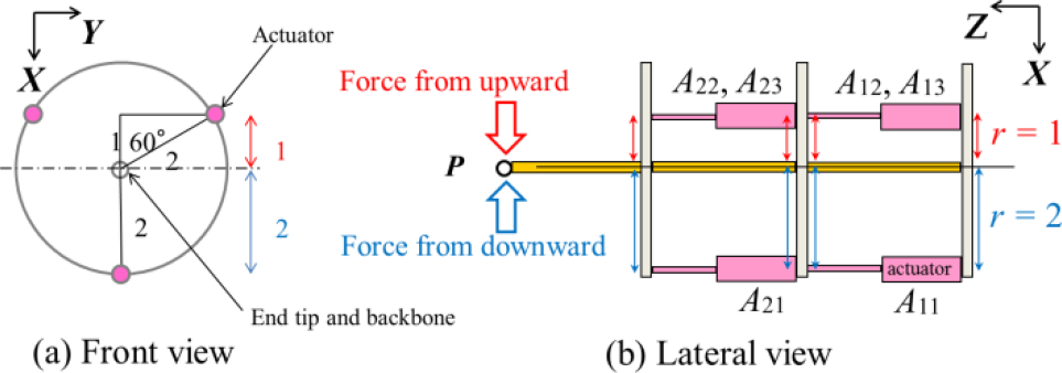
Moment arm from backbone to actuator in arm
As shown in Table 2 and Figure 16, SLD had a larger c than RGD+4 despite the lower initial air pressure. This means that the tension spring and viscous grease in the slider had a larger effect than adjusting the actuator's air pressure on the oscillatory convergence. In RGD+i (i = 1…5), damping ratio ζ did not have a great effect, as shown in Figure 15; however, c was confirmed to change quadratically in a similar manner to k, as shown in Figures 14 and 16.
With regard to the approximated ideal oscillatory waveforms, cycle T did not show a large difference between RGD and SLD; however, SLD converged to the stationary state more quickly because of the larger damping ratio ζ, as shown in Figures 15 and 17(a). Increasing the air pressure of the actuator shortened the time of convergence to the stationary state. The vibration amplitude was also lessened in RGD+i (i = 1…5). On the other hand, the impact force FIm was strengthened, as shown in Figure 18. ELS+SLD, ELS, and HYB, which used elastic backbones, had larger vibration amplitudes and required more time for convergence to the stationary state. This in turn suppressed FIm.
The following summarizes the evaluation of the devices. The slider device improved the workspace with and without the load, collision responsiveness (i.e., oscillatory convergence), and impact absorption. The only disadvantage was the increase in weight from the addition of the slider. However, this weight gain was a fraction of a percent of the weight for the whole arm system. In our previous study, we confirmed that any increase produced for the trunk load was paltry using a dynamic simulator [20]. The tension spring and viscous grease in the slider contributed to the oscillatory convergence and impact absorption of the arm. Therefore, the device can be further optimized by considering the spring and grease as parameters of the arm design.
The elastic backbone did not improve the workspace, both with and without the load and oscillatory convergence because of the excessive flexibility compared with the benchmark configuration RGD. Thus, using it under the current specifications is unfeasible. However, by adding a new device, the backbone may enlarge the workspace in the direction of the applied external force. Moreover, the elastic backbone shows more improvement in the impact absorption than the rigid backbones of RGD or SLD, as shown by impact force FIm in Figure 18. Thus, new methods that utilize this property should be investigated further. For example, when comparing ELS and HYB with the rest of the configurations, the properties of the slider device in HYB were cancelled out by those of the elastic backbone; thus, ELS and HYB showed similar FIm. In this way, the elastic backbone had a large effect. On the other hand, there was a difference between ELS with HYB because of the bulk difference in the backbone's elastic element. By adjusting the bulk, a configuration that has a better balance of the above properties can be developed.
The changes in the spring constant k and viscous damping coefficient c were confirmed by comparing the experiment results of RGD+i (i = 1…5). In particular, Figures 14 and 16 show that a quadratic relationship appeared in the experimental results. This means that the viscoelasticity of the arm itself can be controlled to some extent by adjusting the air pressure of the actuator. Thus, the control technique may improve the performance of the arm. The air pressure influences the oscillatory convergence and impact absorption, which have a trade-off relationship as shown in Figures 17(b) and 18. For example, because the impact is absorbed by the arm's soft motion and the oscillatory convergence is then impacted by the arm's hard motion, the arm should be able to combine the conflicting properties of impact absorption and oscillatory convergence if the actuator is normally set to low air pressure and changes to high pressure soon after collision (accurately after the half cycle) through the use of a force sensor.
Regarding the viscoelasticity, the arm's viscosity in all configurations was around 1 Ns/m as shown in Figure 16. In other related studies [21, 22, 23], the impedance of the human arm or hand was measured in various motions. The viscosity was estimated at around 0 – 100 Ns/m, and it was shown that the value is likely to change even in the process of one motion. The values are comparable to the viscosity achieved in our study. The variety might be due to the difference in the measurement method, the measured motion or output force and weight in the human arm (around 10% of the total body weight [24]) and our lightweight arm (0.7 kg in Table 1). In this study, in the experiment, the arm was tested for only one posture: the arm extended horizontally and the weight was loaded on the hand, as shown in Figure 6(c). Certainly, in the near future, the arm should be tested for other postures and conditions, to investigate the posture-dependent viscoelasticity.
6. Conclusion
We developed a prototype of a small pneumatic elastic actuator-driven basic parallel link arm to act as the benchmark (RGD). We fabricated devices to enhance the spatial accessibility and disturbance responsiveness that were embedded in the prototype: a sliding antagonistic mechanism and soft backbone.
We conducted motion experiments with this prototype arm to examine the workspace with load. We conducted collision experiments to investigate the spring constant, damping ratio, and viscous damping coefficient (i.e., viscoelasticity) of the arm and confirmed its collision responsiveness. Arm configurations that employed various combinations of the slider and changes in the actuator's air pressure showed that the workspace and viscoelasticity of the arm can be improved compared with the RGD, thus ensuring its safety. In particular, the slider device was able to achieve the above properties at the same time. The elastic backbone showed potential with additional refinement.
An individual user may desire to change the dimensions or specifications of an arm because of his or her physical body's measurements and daily lifestyle. Thus, optimizing the parameters that affect the viscoelasticity of the arm, such as the spring and grease in the slider or the arm's physical dimensions, is a new challenge. A control technique that utilizes these new innovations needs to be established.
Footnotes
7. Acknowledgements
This work was primarily supported by JSPS KAKENHI Grant No. 25922011.