
Abstract
This paper studies a robust target recognition and localization method for a maintenance robot in a space station, and its main goal is to solve the target affine transformation caused by microgravity and the strong reflection and refraction of sunlight and lamplight in the cabin, as well as the occlusion of other objects. In this method, an Affine Scale Invariant Feature Transform (Affine-SIFT) algorithm is proposed to extract enough local feature points with a fully affine invariant, and the stable matching point is obtained from the above point for target recognition by the selected Random Sample Consensus (RANSAC) algorithm. Then, in order to localize the target, the effective and appropriate 3D grasping scope of the target is defined, and we determine and evaluate the grasping precision with the estimated affine transformation parameters presented in this paper. Finally, the threshold of RANSAC is optimized to enhance the accuracy and efficiency of target recognition and localization, and the scopes of illumination, vision distance and viewpoint angle for robot are evaluated to obtain effective image data by Root-Mean-Square Error (RMSE). An experimental system to simulate the illumination environment in a space station is established. Enough experiments have been carried out, and the experimental results show both the validity of the proposed definition of the grasping scope and the feasibility of the proposed recognition and localization method.
Keywords
Introduction
Astronauts use video and other instrumentation to monitor a space station cabin. Cabin maintenance and operations involve various movements, such as touching, plugging and pressing [1], [2]. However, the harsh environment of space prevents astronauts from spending long periods of time in the space station. This challenge is further compounded by numerous operational tasks that must take place in narrow spaces and in a microgravity environment. Currently, technological limitations render long-term operational efficiency on a space station unfeasible. Therefore, there is an urgent need to develop a maintenance robot capable of providing assistance to (or replacing) astronauts for operational tasks such as maintenance and other general spacecraft operations. Although this task presents significant technical challenges, it also offers the possibility of increased astronaut safety as well as economic benefits [3], [4].
Space station cabin maintenance robots require target tool recognition and localization abilities to complete maintenance tasks and operations [5]. The National Aeronautics and Space Administration (NASA) has researched space robots for several years and achieved some advances, such as Robonaut [6] and Robonaut 2 [7], [8]. The humanoid robot is designed to use the same tools as space-walking astronauts. Robonaut 2′s integrated mechatronic design results in a more compact and robust distributed control system with a fraction of the wiring of the original Robonaut. In addition to the improvement of force control and sensing the vision modularity has potential to develop further. The most important problem of the vision system is that the large metal surface of the space cabin may result in strong reflection and refraction of light in the cabin, resulting in images with uneven illumination collected by the robot visualization system [9]. Specifically, the change in illumination that occurs near the porthole could cause serious interference to the recognition and localization systems (Figure 1). Furthermore, recognizable objects may undergo affine transformation because of the effect of microgravity [10], which can cause the target recognition task to fail and the accuracy rate to decline. Therefore, it is crucial to develop a target recognition and localization method capable of overcoming illumination and target affine transformation.

Illumination environment in the space station cabin. The left image shows the strong reflection and refraction of light, which is caused by the metal surface in the cabin. The right image shows sunlight near the porthole.
Target recognition is the foundation of target localization; feature extraction is the main component of target recognition. In order to solve the specific environmental challenges in a space station, feature extraction should be invariant to change in both illumination levels and image affine transformation. Slater and Healey [11] propose a method based on local colour invariants for target recognition. The method is unaffected by target location and position, but the effectiveness is low under identical colour object interference. Wu and Wei [12] present an invariant texture method based on a rotating sample and the Hidden Markov Model (ITMM). This method is invariant to rotation and grey transformation and is confined to recognizing similar regions in independent locations. Gevers and Smeulders [13] propose a method that combines colour and shape in order to extract features that are invariant to geometry and illumination. Although this method is robust and highly efficient for target recognition, target discernment decreased with change in moment invariant features. Hence, existing research indicates that feature extraction methods based on global variables cannot adequately address the problem of target occlusion.
Vision-based target localization for space station robot is essential to maintenance robot grasping. Generally, an infrared target recognition and localization system is used for a free-floating space robot [14], [15]. However, this method is sensitive to external disturbance, such as noise and complex background. Meanwhile, pose estimation based on camera has been studied. A closed-form analytical solution to the problem of three-dimension (3D) estimation of circular feature location is presented in reference [16]. This method considers 3D estimation and position estimation when the radius is unknown. But it is confined by the fact that circles must exist in the surface of the target. R. T. Fomena proposes a method which is concerned with the use of a spherical projection model for visual servoing from three points [17], Although this method is robust to points' range errors, it is not perfect for tool localization because the point itself is difficult to pinpoint. Based on the spherical projection model, another method is proposed by using three independent translation parameters and invariance to rotational motion to estimate pose [18]. Due to limitations of a single camera, such as limited field-of-view, it is not suitable for space station tool localization. In F. Janabi-Sharifi's paper [19], an algorithm named Iterative Adaptive Extended Kalman Filter (IAEKF) is proposed by integrating mechanisms for noise adaptation and iterative measurement linearization. This method can estimate position and orientation of an object in real time based on robot vision system. But the non-linearities are usually the main reason for the failure of filtering strategies of the pose, especially during abrupt motions and occlusions.
Based on local interest point feature extraction, a method, called Scale Invariant Feature Transform (SIFT), is proposed by D. Lowe [20], [21], and has a wide application in object tracking and localization [22], [23]. The extracted features are invariant to image scale and rotation, and are shown to provide robust matching across a substantial range of affine distortions, 3D viewpoint changes, occlusion addition, and illumination changes. However, the overall number of matching points will greatly reduced and the number of incorrect matching points will increase when the viewpoint angle of the target grows larger. Based on the SIFT model, Ke and Sukthanka present a method that utilizes principal component analysis, which is called Principal Component Analysis and Scale Invariant Feature Transform (PCA-SIFT) [24]. This method reduces the dimensions of the SIFT feature descriptor effectively. Subsequently, Hakim and Farag propose a Colour Scale Invariant Feature Transform (CSIFT) algorithm for colour images [25] and Bay proposes the Speeded Up Robust Features (SURF) model [26]. Although these methods can solve the problem of complex calculations and time consumption to some extent, the number of matching points and the accuracy are both lower than SIFT. In order to solve the problem of fewer matching points under large affine distortion, Yu and Morel present a fully affine invariant algorithm named Affine-SIFT that treats the two left-over parameters: the angles defining the camera axis orientation [27], [28]. This algorithm is efficiently implemented by using the difference-of-Gaussian function to identify potential interest points that are invariant to scale and orientation. The key point descriptor is represented relative to the orientation and this enables invariance to image rotation and noise by assigning a consistent orientation to each key point based on local image properties. Moreover, the descriptor becomes invariant to affine changes in illumination by creating orientation histograms and modifying the feature vector. Furthermore, the method handles transitions of 36 tilts and above [28]; it also obtains a large number of matches (compared to other algorithms) to simulate all views by using the angles that define the camera axis orientation. The ASIFT algorithm has now been used in remote sensing image stitching, image registration and other image-related operations [29], [30]. However, this method has rarely been used for target localization.
In addition, in order to estimate mismatched points because of the inevitable occurrence of mismatched points under the ASIFT algorithm, the Random Sample Consensus (RANSAC) [31] algorithm (proposed by Fischler and Bolles) is used in this paper. Then, the affine transformation model is established and the affine transformation parameters are obtained. Finally, the three-dimensional (3D) coordinates of the grasping point and range of the target tool are calculated using the binocular vision system.
In summary, in this paper we want to argue that the method we presented is an appropriate approach to achieve a general, robust and versatile vision system for all of the target tools used in the space station cabin.
This paper is organized as follows. Section 2 describes a space station cabin robot system, a target recognition and localization system scheme. Section 3 establishes the affine transformation model and obtains the correct matches based on the ASIFT & RANSAC algorithm. Section 4 introduces the definition of grasping key points and grasping scope, as well as the target localization method by using the estimated parameters and a binocular vision system. Section 5 uses the proposed method to conduct a series of experiments under different illuminations, affine transformations and occlusions, and eventually contrasts the accuracy and processing speed of three methods. Finally, section 6 summarizes the main contributions and also presents areas that merit further research.
Robot system architecture
Implementation of a grasping command for a given object is a fundamental task for a space station cabin maintenance robot when assisting (or replacing) astronauts with cabin operations. The key to grasping is the accurate recognition and localization of the target. Common repair tools are chosen as targets for recognition and localization. A target recognition and localization system for a space station cabin maintenance robot is built to test target recognition (Figure 2). The humanoid space robot consisted of a head with a binocular vision system, two arms, a trunk and 16 degrees of freedom (DOFs).

Humanoid space robot
A binocular stereovision system is built into the head of the robot. In order to ensure wide coverage of the vision system, the vision platform of the space robot head is designed with two DOFs. A Permanent Magnet Synchronous Motor (PMSM) and a harmonic reducer are used to drive the DOFs, ensuring that the cameras move accurately and smoothly to the desired targets. The positions of the target tools are calculated using the binocular stereo vision system of the robot.
Figure 3 shows the target recognition and localization system scheme based on the humanoid space robot. First, the appointed target will be recognized. By using the local interest point feature extraction algorithm to obtain the matches between the reference image and the experimental image, the mismatched points are eliminated. Then, the affine transformation model is established, and the transformation parameters can be estimated using the stable matching points. Second, we define the key points and grasping scope of the reference image, and calculate the 2D coordinates of the transformed key points based on the transformation parameters. On the basis of the parallax principle of the binocular vision system, the 3D coordinates of the target key points and the grasping range are obtained. Target identification and localization are completed under these two mechanisms. The whole process is implemented through the image processor DSP and FPGA.

Flowchart for target recognition and localization
In this section, two asymmetrical and symmetrical target tools are selected, and the space station cabin illumination environmental simulation system is established. Based on the target and system, the key points of the target and affine transformation parameters which are used to recognize and localize the target are obtained using ASIFT & RANSAC algorithm.
Target and illumination environment simulation
The maintenance tools used in the space station can generally be divided into asymmetrical ones and symmetrical ones (Figure 4). In order to prove the presented algorithm is applicable to both tools, a common wrench has been chosen as the asymmetrical sample target and a common pair of pliers is used as the symmetrical sample target.

Maintenance tools used in the space station
Figure 5 shows simulated space station cabin lighting conditions. These are simulated using an illumination environmental simulation system that included both a lamplight system and sunlight irradiation. In the space station cabin, because the metal surfaces might cause the strong reflection and refraction of light, to simulate the actual environment, we design a metal operating desk, a metal box and a metal plate around the robot.

Illumination simulation system
The illumination conditions are quantitatively analysed by controlling the number of light sources and the sunlight irradiation at noon in the experimental environment. There are three illumination conditions based on the lamplight system, classified as strong, medium and weak light sources. Non-sunlight and sunlight irradiation is controlled by curtain openings. Altogether, there are six levels corresponding to the different illumination conditions (Table 1).
Illumination conditions
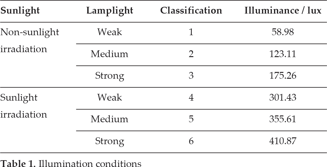
For a quantitative description of light, the illumination intensity of the captured images in the six illumination levels are measured. Under non-lamplight condition, the indoor intensity of illumination on a sunny day is 256.73 lux measured by the illuminometer whose model is SS-TES-1339R, and it decreases to 9.14 lux without the sunlight irradiation. Controlling both sunlight irradiation and lamplight illumination at the same time, the specific illumination intensity of six illumination levels are measured and shown in Table I.
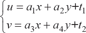
During the target recognition process, the captured images are divided into two parts: reference image and experimental image (Figure 6). For easy evaluation of the accuracy of the estimated affine transformation parameters using the present method, each of the transformations is determined by the known matrix

Reference images stored in the library. Image (a) is the reference image of wrench. Image (b) is the reference image of pliers.
Figure 6 shows the reference images that are captured at the front view when the target tools are vertical and under the third illumination level (non-sunlight and strong lamplight conditions). The reference images will be stored in the library, enabling the matching points to be extracted during the test. The experimental images under different environmental conditions will be provided in section 5.
All of the captured images are saved as 800 × 600 pixels, for the following reasons. On the one hand, the size is small enough to accelerate the image processing speed; on the other hand, it is not small enough to miss numerous vital details of the target. Because a binocular visual system includes two cameras, in order to avoid the confusion of whether the images are captured by left camera or right one, from now on, all of the presented images are captured by the left camera.
ASIFT
ASIFT is an affine invariant feature extraction and matching method based on SIFT. It is not only fully invariant with respect to zoom, rotation and translation, but also treats the angles defining camera axis orientation.
In 2004, Towe proposed the SIFT algorithm. The major stages used to generate a set of image features include scale-space extreme detection, key point localization, orientation assignment and key point descriptors. This enables the generation of a 128-dimensional feature vector for each key point. The Best-Bin-First algorithm is then used to obtain the minimum Euclidean distance for the invariant descriptor vector between the reference image and the collected image. The best candidate match for each key point is then selected from these images. However, mismatching and a decrease in the number of matching points occur when the target undergoes significant affine distortions.
The ASIFT algorithm fundamentally enables the simulation of all views to achieve fully affine invariance based on the angles defining the camera axis orientation. The projection transformation of the image is simplified to the affine transformation model. The transform matrix has a decomposition shown by equation (1).

Where λ is the scale factor; ψ is the angle between the camera and the optical axis; and t is the absolute tilt rate of the camera, determined by the latitude angle of the optical axis, θ. t = 1/cosθ, where ϕ is the longitude angle of the optical axis. Figure 7 shows a camera motion interpretation of equation (1).

Affine transformation model
A series of affine transformation parameters are obtained by sampling the longitude angle, ϕ, and the latitude angle, θ, of the camera optical axis. The obtained transformation parameters are then used to transform the reference images and the target images. This step simulates the original images distorted under any affine transformation. Next, the feature vectors of the transformed images are extracted using the SIFT algorithm. Figure 8 shows the algorithm flowchart of ASIFT.

Algorithm flowchart of ASIFT
The Random Sample Consensus (RANSAC) algorithm was used to eliminate the mismatched feature points. In 1981, Fischler and Bolles published the RANSAC algorithm at SRI International (SRI). First, an objective function will be designed based on that discussion. The data is assumed to consist of ‘inliers’ (data distribution explained by a set of model parameters) and ‘outliers’ (data that do not fit the model). RANSAC assumes that, given a set of inliers, there exists a procedure that can estimate the parameters of a model that optimally explains or fits these data.
This research aims to eliminate mismatched feature points; as such, the transformational matrix is chosen as the objective function. Reference image I (stored in the library) and target image C satisfy the affine transformation relationship, such that:
where I (x, y) and C (u, v) represent a feature point of reference image I and collected image C, respectively. Equation (2) can be written in matrix form as:

where H represents the transformational matrix of I (x, y)→C (u, v); A is the affine transformational matrix, which includes scaling, rotation and shearing; and T is the translation vector.
At least three non-collinear matching points are required to calculate the transformational matrix H. The equality relationship is:

This equation is solvable when there are more than three matching points. Based on the above analysis, four steps are used to implement the RANSAC algorithm:
Three matching points are selected from matching points set S; the transformational matrix, H′, is calculated using equation (4);
The matching points belonging to reference image I are selected from the remaining elements of set S; equation (3) calculates the transformed results and errors based on matrix H′; the agreement set of matrix H′ is established along with the set that includes the points where the error value is less than the threshold, t h (in section 5, t h will be determined by repeated experiments);
The number of the agreement set is updated when it is more than the threshold, T, whose initial value is set at 0. The threshold, T, became the new number of the agreement set;
Set K = 1000 is selected and the process above is repeated until the iterations are completed. The agreement set with the most points is then obtained. Based on these points and using equation (4), the transformational matrix, H, is obtained.
The Root-Mean-Square Error (RMSE) is a measure of the feature points that are precisely matched based on ASIFT and RANSAC algorithms.

The statistical error threshold is set at t h ; as such, the requirements are satisfied as long as the RMSE is less than t h .
In the space station cabin, microgravity and the general movement of the station result in target transformation and occlusion, which make target localization much more difficult than on Earth. Furthermore, features of key points and grasping range are difficult to extract under a special illumination environment. This paper proposes a method to calculate two key points of a transformed target based on grasping points' definition and estimated transformation parameters (section 3), and then obtaining the 3D coordinates of the grasping points and three Euler angles based on a binocular vision system.
Determination of 3D coordinates
For convenience of localization and target tool grasping, the 3D coordinates of a grasping point and three Euler angles of the target should be calculated. In order to obtain the six parameters, two key points k1(x1, y1), k2(x2, y2) are selected from the target tool. Two coloured circles are added to the reference images (Figure 9). The two circles are segmented based on the HSV colour space and the contour shape feature is extracted to obtain the centre coordinates. Therefore, the target coordinate system can be defined, which is determined by the two key points k1′, k2′, with the original point k2′ and the direction of X axis (direction of vector K2′K1′).
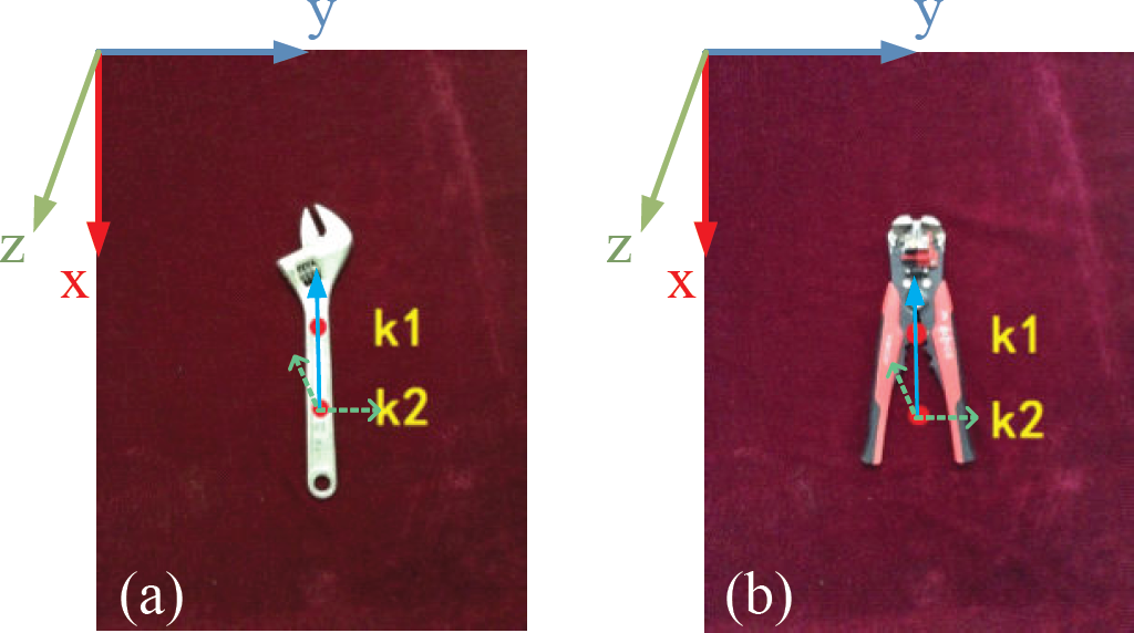
Key points of the reference image. Image (a) is a wrench, image (b) is pliers.
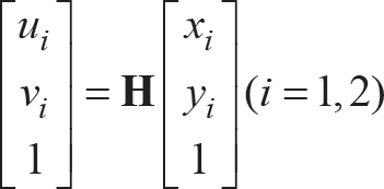
Based on section 3, the transformed matrix, H, can be estimated when the wrench is transformed from the reference image position to the collected image position. Using the coordinates k 1 , k2, matrix H, and equation (6), the coordinates of the transformed k1′(u1, v1), k2′(u2, v2) are obtained.
The left camera coordinate system is selected as the world coordinate system. The 3D coordinates K1′(X W , Y W , Z w ), K2′(X W , Y W , Z W ) in the world coordinate system are calculated based on the binocular camera internal and external parameters, M L , M R , and equation (7).

Where A1L, A1R and A2L, A2R are the matrixes of internal and external parameters of the left and right cameras, respectively. The centre of the line K1′K2′ is selected as the localization grasping point O′(X W , Y w , Z W ).
The Euler angles of the transformed target are determined by vector K2′K1′. For a target tool, both the 3D vector K2K1 of the reference image and the 3D vector K2′K1′ of the transformed image can be calculated based on the binocular vision system. Therefore, the rotation angles between vector K2K1 and K2′K1′ can be represented by quaternion form. Then, three Euler angles ψ, θ, φ, which are the rotation angles around the Z axis, Y axis and the X axis, respectively, will be obtained by transforming the quaternion.
Considering the size of target tools, we define the accurate grasping scope: a cylinder. The centre of the cylinder is O(X W , Y W , Z W ) and the height is 1.2 times that of line K2K1, and the radius is the same as the radius of the red circles (radius equals 7.5 mm) on the target. This definition means that the grasping motion is accurate as long as the localization results (O′(X W , Y W , Z W ) and vector K2′K1′) are included in the cylinder. The size of the cylinder is closely related to both the angle of view and the scraping precision of the robot, and it can be redefined by the specific scraping precision.
Experimental results
To test the feasibility and effectiveness of the above algorithm, three groups of experiments based on the simulation of the special illumination environment are conducted. The experiments include estimations of the transformation parameters and target localization under the following conditions: same transformation and different illumination; same illumination and different transformation; different illumination, transformation and occlusion.
Recognition results under different illumination levels
In this test, images for each tool are captured under six different illumination levels (Table 1) with the same transformation, H1 and H2, respectively (Figure 10). In order to eliminate the influence of uncertain exterior factors, 20 images are captured and saved under each light level. Hence, there are 20 sets of images and each set contains six images. At this section, as only illumination is the influencing factor, we thus set matrix H1 and H2 as the actual transformation matrix for all the captured images of wrench and plier, respectively.

Target images of wrench and plier under different illuminations when the transform matrix is H1 and H2, respectively. Images (a) are transformed images of wrench, and images (b) are transformed images of plier.
The illumination intensity changes from 58.98 lux to 410.87 lux. The number at the bottom left of each image corresponds to the illumination level. For convenience of explanation, we will use the number on behalf of the illumination conditions in the following discussion. Figure 10 also shows the coordinate system of each target tool.
Take one set of images as an example and analyse the determination of threshold t h . Figures 11 (a) and (b) show the number of matching points (based on ASIFT and combined ASIFT & RANSAC algorithm) between the reference and transformed images under different illuminations. The X axis represents the illuminance for six illumination levels, and the Y axis shows the number of matching points. Each figure includes six curves corresponding to the threshold t h which changed from 1 to 10. Threshold t h must be chosen to be large enough to satisfy two conditions: that the correct model should be found for the data, and that a sufficient number of mutually consistent points should be found to satisfy the needs of the final smoothing procedure. In order to obtain the optimum threshold t h to eliminate the wrong matching points as far as possible, and at the same time to make sure that the number of matching points is not too small, t h = 4 is chosen based on Figure 11 (c) and (d). This is because the number of matching points decreases sharply when t is less than 4, and it declines slowly when t is more than 4. The result also fits for the following experiments.

Number of matching points based on ASIFT and combined ASIFT & RANSAC algorithm between the reference and transformed images under different illuminations, where the threshold t h was valued 1, 2, 4, 6, 8 and 10
This experiment takes the image of the plier under non-sunlight and weak lamplight (the first image of Figure 10 (b)) as an example to show the matching point image based on the ASIFT algorithm and the combined ASIFT & RANSAC algorithm (Figure 12). Figure 12 (a) shows the matching points based on ASIFT, where the white lines are the connecting lines of the wrong matching points and the black lines are the same as in Figure 12 (b), which are the matching points based on ASIFT & RANSAC algorithm. The white lines show that there are many mismatching points under first illumination level, and the blue ones show the matching accuracy of the remaining points after RANSAC screening is satisfied.
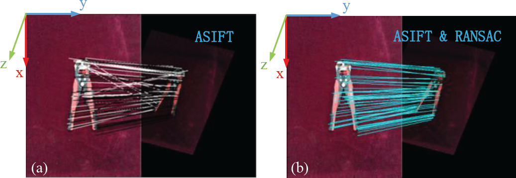
Image of matching points of the plier under first illumination level. Image (a) is the matching point image based on ASIFT algorithm. Image (b) is the matching point image based on combined ASIFT & RANSAC algorithm.
The transformational matrix under six illumination conditions based on matching points after screening can be estimated. Comparing the estimation values and the affine transformation model H1, H2, the RMSE of each image is obtained (Figure 13). Figure 13 shows the values are relatively high under both weak and strong illumination, but all of the RMSE values are less than the threshold t h which is 4. These values verify that the method of affine transformation parameter estimation based on the combined ASIFT & RANSAC algorithms is invariant to illumination.

Curve of RMSE values under six illumination conditions for both wrench and plier (threshold t h = 4)
The 3D coordinates of the reference vector K2Kt and the transformed vectors K2′K1′ can be calculated based on the binocular vision system (Figure 14). In Figure 14, the red solid line is the reference vector K2K1, and the rest of the lines are the transformed vectors K2,K1′, where the blue solid line represents the actual transformed vector. Furthermore, Figure 14 also shows the grasping scope of the cylinder. The results show that all of the transformed vectors K2′K1′ are contained by the cylinder.
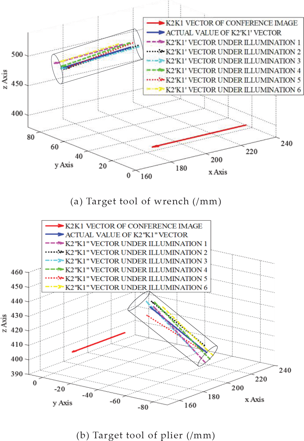
Coordinates of target vector and grasping scope under different illumination conditions
Additional experimental processes for all 20 sets of images are repeated, and the localization accuracies are achieved: 94.17% for wrench and 93.33% for plier. At the same time, we also get the average frame speed of 26 frames per second. This demonstrates that the 3D localizations for both the symmetric and asymmetric targets are accurate.
In this section, a series of transformations are set up to test the effect of a change in target position. For the same reasons as described in section 5.1, 20 sets of images are captured at the same light level and position. The position of the target, including H1, H2, H3, H4, is changed under the third illumination level (non-sunlight irradiation and strong lamplight).
Figure 15 shows the transformed images of one set of wrench and plier images, respectively, which have varying degrees of rotation, shearing, scaling and translation to simulate the change of the target position.

The number of matching points based on ASIFT and combined ASIFT & RANSAC algorithms between the reference and transformed images under different transformational matrixes are shown in Figure 16. The threshold t h = 4, based on section 5.1.
After screening the inaccurate matching points, the transformational matrix under different transformation can be estimated, and the RMSE of the estimation values and the affine transformation model are obtained (Figure 16). It is obvious that all of the RMSE values are less than threshold 4.

Image (a) is the number of matching points based on ASIFT and ASIFT & RANSAC algorithms under different transformation matrix (t h = 4). Image (b) is the curve of RMSE values under different transformational matrix for both wrench and plier.
By repeating the above method to process all 20 sets of images, the corresponding RMSE value of each image can be obtained, and the accuracies for wrench and plier are 97.5% and 98.75%. The results verify that the proposed method is invariant to affine transformation.
To achieve the range of scale, extensive tests have been carried out, and the results are shown in Figure 17. The results are the average RMSE value of the 20 captured images under a certain scale or viewpoint angle. It can be seen that both the RMSE values of wrench and plier are below the threshold (t h = 4) when the scale changes from 0.3 to 2 times the initial reference image. So, we can conclude that the proposed method is applicable to changes in scale from 0.3 to 2.

RMSE values with different scales. Because of the limited view-angle coverage, when scale equals 2 the target is out of the image range, so the maximum of scale is 2. Figure also shows that the value of RMSE exceeds the threshold t h = 4, when scale equals 0.2.
The sensitivity of the estimated transformational matrix to viewpoint angle (include both longitude and latitude) change is examined in Figure 18. The graph shows the changing of RMSE values between the actual transformed matrix and the estimated matrix with different viewpoint angles. The solid lines show the RMSE value of target wrench, and the dotted lines represent the RMSE value of the target plier. The blue curves (solid one and dotted one) are the RMSE value under changing longitude when the latitude is zero, and the red ones are the values under different latitudes when the longitude is zero. The green curves show the value of RMSE under different longitude and latitude, but the two angles are the same.
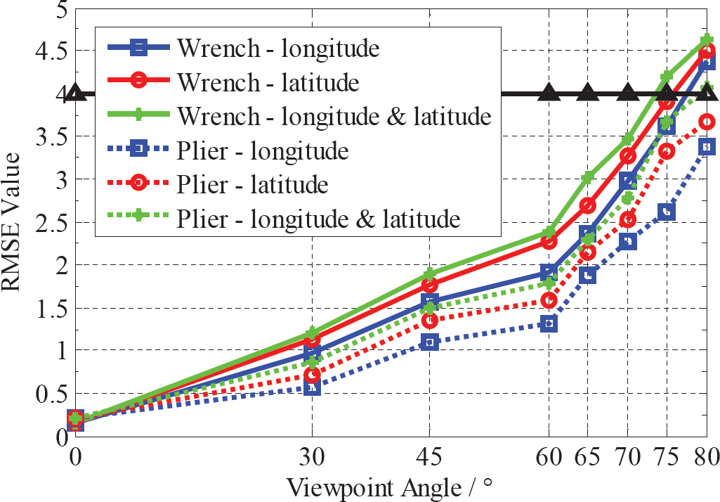
Curve of changing RMSE value with increasing viewpoint angle. The angle contains three conditions in order to achieve a fully affine distortion.
It can be seen that each stage of RMSE value has risen repeatedly with increasing affine distortion, and we can see especially that some of the final values exceed the threshold when viewpoint angle rises to 80 degree. Figure 18 illustrates that all of the RMSE values are less than the threshold t h = 4 when viewpoint angle (both longitude and latitude) changes from 0° to 75°.
To verify the accuracy of the 3D coordinates of the transformed vectors K2′K1′ of the targets in Figure 15, Figure 19 shows the calculated results corresponding to the four matrixes. Because the transformational matrix model for wrench and plier are the same, the 3D coordinates of the vectors are shown in the same way, Figure 19 (a). Matrix H1, H2, H3, H4 in Figure 19 (a) corresponds to the four groups of transformed vectors. As it is difficult to find an appropriate view position to show all of the transformed vectors, we give them the larger vision, which shows the 2D (X axis and Y axis) images (Figure 19 (b), (c), (d) and (e)). From the larger visions, all of the transformed vectors K2′K1′ are contained by the cylinder. The larger visions show that the 3D localizations for both the symmetrical and asymmetrical targets are accurate under four different transformational matrixes.

Coordinates of target vector and grasping scope under different transformational matrix (/mm)
According to the localizations of all 20 sets of images, the accuracy for wrench is 96.25%, and plier is 97.5%, and the average frame speed was 27 frames per second. The experiment verifies that the proposed method is invariant to affine transformation.
The third experiment addresses recognition in complex conditions, including different illumination, affine transformation and occlusion. In this section, we set five different types of target occlusion, and in each occlusion a set of different illuminated images is captured which includes six images. Then, five transformational matrixes, H, are selected to transform the above 30 images captured for each target. Finally, a total of 150 images under varying degrees of occlusion, illumination and transformation are obtained. Figure 20 shows one set of the images for each of the target tools (wrench and plier), corresponding to matrixes H1 and H2, respectively. Other tools, such as scissors, awl and a circular coil occlude the target in the collected images.

Images of target tools corresponding to matrixes H1 and H2 under different illumination and occlusion conditions
Based on section 5.1, we chose t h = 4 as the threshold. The number of matching points based on ASIFT and combined ASIFT & RANSAC algorithms under complex conditions are shown in Figure 21 (a). The X axis represents the illuminance for six illumination levels. For this test, there occur not only lighting effects but also different degrees of occlusion. Thus, the number of matching points decreased sharply compared with the former two groups. Although the matching points are relatively fewer in quantity, the RMSE value of each transformed image fulfils the requirement compared with threshold th = 4 (Figure 21 (b)).

Image (a) was the number of matching points based on ASIFT and ASIFT & RANSAC algorithms under complex conditions. Image (b) was the curve of RMSE for both wrench and plier.
Figure 22 shows the 3D coordinates of the reference vector K2K1 and the transformed vectors K2′K1′ From the larger vision, all of the transformed vectors K2′K1′ are contained by the cylinder. It shows that the 3D localizations for both the symmetrical and asymmetrical targets are accurate under complex conditions.
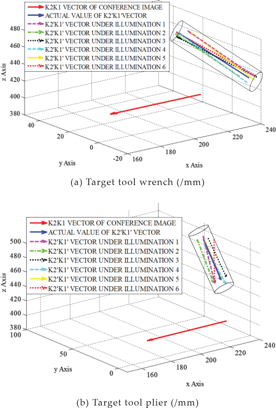
Coordinates of target vector and grasping scope under complex conditions
By calculating and analysing the recognition and localization results of all 150 images of each target tool, we calculate that the accuracy for the wrench is 89.33%, and for the pliers 88.67%. Moreover, we determined that the average frame speed was 23 frames per second. The experiment verified that the proposed method was invariant to space illumination, affine transformation and occlusion. Therefore, we can come to the conclusion that the maintenance robot can successfully use this method to accurately localize and grasp the transformed target under reflection and refraction of light in a cabin and a space microgravity environment.
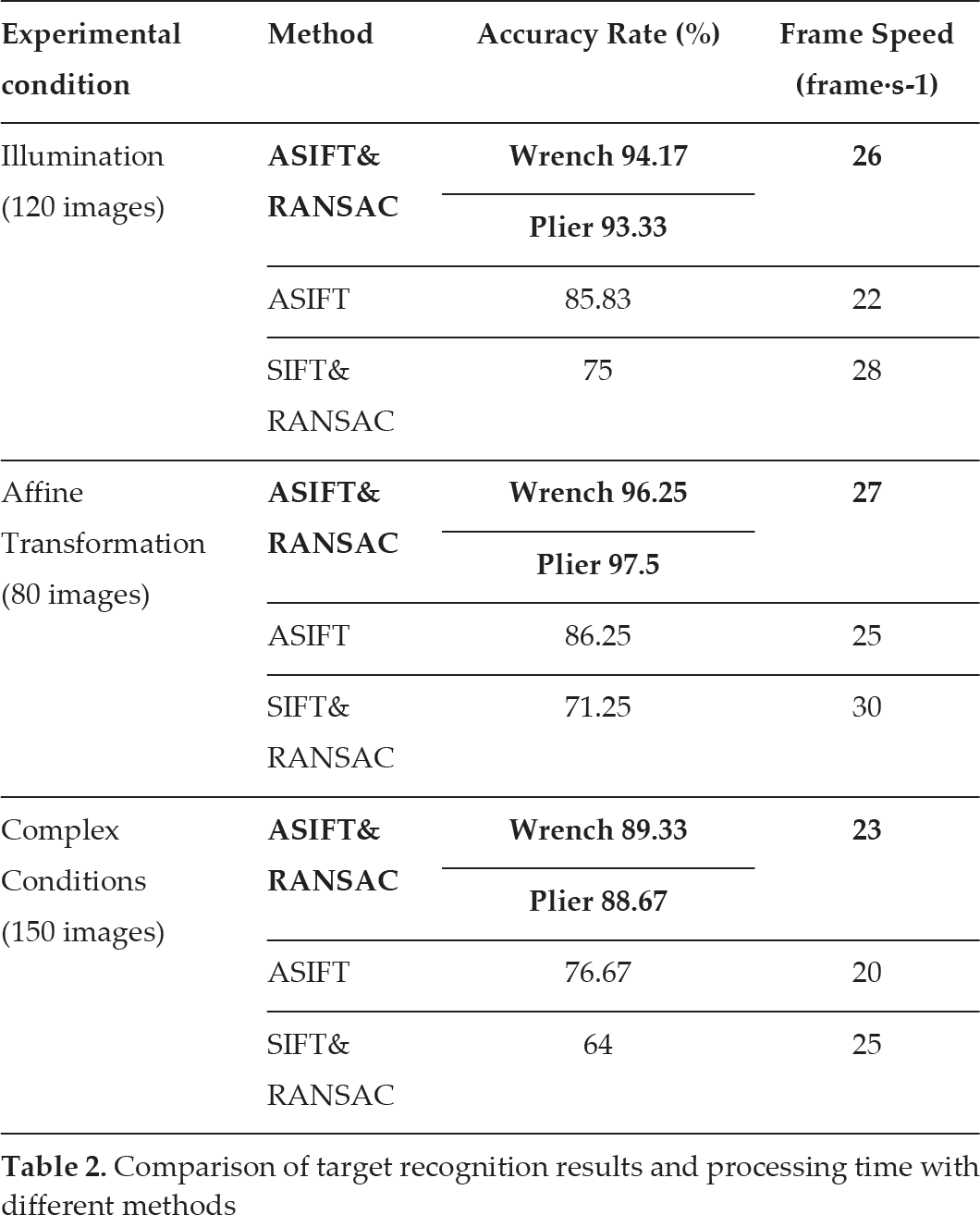
Based on the above research and experiments, a series of data are calculated. For further comparison with some previous methods, such as ASIFT, SIFT & RANSAC, etc., additional experiments are carried out, and the results are shown in Table 2. From the above results, it is obvious that the accuracy and processing speed for asymmetrical tool wrench and symmetrical tool plier have no distinct differences, so, in additional experiments, we select the asymmetrical wrench as the target for both ASIFT algorithm and SIFT & RANSAC algorithm.
Comparison of target recognition results and processing time with different methods
Comparison of target recognition results and processing time with different methods
The results of these experiments demonstrated that the object recognition and localization method, by combining Affine-SIFT and RANSAC, is sufficiently accurate and feasible. Compared with the ASIFT method, ASIFT & RANSAC has greatly increased efficiency both in accuracy and in speed. Furthermore, ASIFT & RANSAC, as an efficient alternative to SIFT & RANSAC, although the speed of operation declines slightly, shows significantly improved accuracy of localization. All the data show that the ASIFT & RANSAC method can solve the interference of different illumination, affine transformation and occlusion robustly and efficiently.
This paper proposed a novel method that could significantly increase the accuracy rate for robot target recognition and localization in a space station. This method made the following contributions:
An estimation method of affine transformation parameters of robot vision target based on ASIFT and RANSAC algorithms. This method could provide robust matching across a substantial range of affine distortion, change in 3D viewpoints, occlusion additions and change in illumination in an illumination environment simulation of a space station.
A new definition for target localization and grasping based on estimated transformation parameters. By combining the target size and the scraping precision of the robot, two grasping points and a cylinder scope of the tool were defined to obtain the 3D coordinates of the grasping point and evaluate the accuracy of positioning results, which could help the robot to accurately localize and grasp tools in a space station.
An experimental system to simulate illumination environment in a space station was established, and enough experiments have been implemented under many special conditions, including different illumination, affine transformation and comprehensive factors. By comparing the influence of different thresholds of the RANSAC algorithm on the number of matching points, the optimized threshold t h was obtained as 4 in this paper for enhancing the accuracy and efficiency of calculation. In illumination experiments, six illumination levels were defined, and the results showed tool recognition and localization was accurate from 58.98 lux to 410.87 lux. In the affine transformation experiment, the limitations of scale (0.3~2 times the target) and viewpoint angle (0° ~75°) were determined.
A set of comparative experimental results was presented based on previous methods (ASIFT and SIFT & RANSAC) and our proposed method (ASIFT & RANSAC). The data verified that this method is robust and efficient.
The robotic visual system should be further studied in order to understand its viability for use in an actual space station environment, in which recognition would occur. A viable system would also need to demonstrate effectiveness in coping with uncertainties that were not considered in this paper, such as the recognition and localization of moving targets.
The algorithm used in this study only focused on robotic visual recognition and localization, because the aim was to propose a method that was invariant to image affine distortion and illumination change. Future studies should focus on the grasp mode of the space robot end executor based on visual positioning, including path planning, system optimization, and enhanced human and robot safety.
Footnotes
7.
The authors wish to express their gratitude to the National High Technology Research Programme of China (Grant 2011AA040202), the Beijing Science Foundation (Grant 4122065) and the National Natural Science Foundation of China (Grant 60925014 and 61273348) and the “111 Project” (Grant B08043) for their support of this work.