
Abstract
The field of Medical Capsule Robots (MCRs) is gaining momentum in the robotics community, with applications spanning from abdominal surgery to gastrointestinal (GI) endoscopy. MCRs are miniature multifunctional devices usually constrained in both size and on-board power supply. The design process for MCRs is time consuming and resource intensive, as it involves the development of custom hardware and software components. In this work, we present the STORM Lab Modular Architecture for Capsules (SMAC), a modular open source architecture for MCRs aiming to provide the MCRs research community with a tool for shortening the design and development time for capsule robots. The SMAC platform consists of both hardware modules and firmware libraries that can be used for developing MCRs. In particular, the SMAC modules are miniature boards of uniform diameter (i.e., 9.8 mm) that are able to fulfill five different functions: signal coordination combined with wireless data transmission, sensing, actuation, powering and vision/illumination. They are small in size, low power, and have reconfigurable software libraries for the Hardware Abstraction Layer (HAL), which has been proven to work reliably for different types of MCRs. A design template for a generic SMAC application implementing a robust communication protocol is presented in this work, together with its finite state machine abstraction, capturing all the architectural components involved. The reliability of the wireless link is assessed for different levels of data transmission power and separation distances. The current consumption for each SMAC module is quantified and the timing of a SMAC radio message transmission is characterized. Finally, the applicability of SMAC in the field of MCRs is discussed by analysing examples from the literature.
Keywords
Introduction
Capsule robots are meso-scale devices that leverage extreme miniaturization to access and operate in environments that are out of reach for larger robots. In medicine, capsule robots can be designed to enter the human body through natural orifices or small incisions, and to perform endoscopy and surgery while minimizing the invasiveness of the procedure.
In general, Medical Capsule Robots (MCRs) are characterized by their small size, (i.e., typically 1 cm in diameter), and their ability to collect information and to interact with the surrounding environment either autonomously or in response to an external command. Wireless or soft-tethered MCRs have been designed to reduce the number of incisions required by laparoscopic surgery [1–4], to perform Natural Orifices Transluminal Endoscopic Surgery (NOTES) interventions [5–8], and to provide advanced functionalities during gastrointestinal (GI) endoscopy [9–13]. Since each application is unique, designing and developing a MCR requires significant skill and effort in prototyping, programming, debugging and miniaturizing the device. These requirements increase the barriers to design space exploration, limiting the number of research groups active in the field to those who possess an adequate background and who can access advanced fabrication and testing facilities. However, many subsystems of MCRs developed thus far are comparable and share some portion of equivalent hardware and software components. These include a large number of low-level design elements, such as sensing, data processing, actuation driving and wireless communication, to perform similar functionalities.
Therefore, it is possible to provide the research community with a number of constitutive bricks that can be assembled together to achieve the desired functionalities and investigate the feasibility of a specific design. Should the proof-of-concept phase be successful, the researchers can focus their resources in custom design optimization to concretely translate their solution into a clinical product.
A first step in addressing the common requirements of MCRs was proposed by the authors in [14], where a pseudo kernel approach was developed. This laid the groundwork for the implementation of a number of devices based on one-time hardware prototyping with the support of reconfigurable firmware architecture [6, 15–18]. By adopting this approach, the firmware development time can be reduced drastically by software layering, but reconfiguring the hardware still requires substantial effort. Having a platform with modular hardware and firmware components would benefit the research community by lowering the barriers to design space exploration, thus accelerating progress in prototyping, as demonstrated by MOTES [19], SAND [20] and ECO [21] for wireless sensor network applications. Similar paradigm shifts are currently taking place in micro aerial vehicle research, with the introduction of open source hardware and software platforms [22, 23], and in robotics, thanks to the availability of the PR2 robot and the development of ROS [24, 25].
In this spirit, this paper proposes the STORM Lab Modular Architecture for Capsules (SMAC) as a modular open source platform for MCRs development. The primary advantages of using SMAC include module reusability, a reconfigurable software library, and the potential for significant support from the free and open source software community. Our main contributions with SMAC are ready-to-use modular hardware in the form of miniature boards featuring a microcontroller with radio, power management, sensor and actuation modules accompanied with a highly reconfigurable and open source software stack. SMAC modularity and reconfigurability allow MCR developers to focus directly on the specific application, without the burden of designing and developing basic functional blocks. Developers can either reconfigure interconnections among existing SMAC modules to meet application requirements, or test and validate their own novel modules by connecting them to existing SMAC components.
This paper is organized as follows: Section 2 presents the requirements of MCRs addressed in SMAC, Section 3.1 describes the SMAC hardware, Section 3.2 describes the firmware structure, and Section 3.3 provides an example of an SMAC application. Section 4 presents the experimental assessment of the wireless link at different levels of data transmission power. In Section 5, we provide an overview of MCRs that have already been implemented with SMAC, together with other examples from the literature that can easily be adapted to our proposed modular approach. This illustrates the potential impact of SMAC in the field of MCRs. Finally, Section 6 discusses conclusions and future works.
Architecture requirements
MCRs are tightly constrained in size and power consumption, and must be fail-safe and reliable in order to operate inside the human body. In addition, the modularity and reusability of both the software and hardware components of MCRs would open this field to a wider community of researchers. In this section, we expand on these requirements and we lay the foundation for our SMAC open platform.
Miniature size
The diameter of a MCR is typically constrained by the entry point into the human body. In Minimally Invasive Surgery (MIS) [1], the MCR must fit the internal diameter of a surgical port, typically from 3 mm to 12 mm. For GI applications [15, 16, 26, 27], we can assume the diameter of commercially available Wireless Capsule Endoscopes (WCEs), (i.e., 11 mm) as the benchmark [28]. Adopting these size constraints as a reference, all of the SMAC hardware modules presented in Section 3.1 have been designed with a round-shaped Printed Circuit Board (PCB) having a maximum external diameter of 9.8 mm. SMAC modules can be stacked to achieve a cylindrical capsule-like shape.
Data connectivity
To reach deep inside the human body, MCRs may be either wireless or softly tethered, depending on the specific application and/or the target anatomical district. In case of MIS, NOTES or GI endoscopy in districts that are close to a natural orifice (e.g., the colon, oesophagus or stomach), a soft tether can be used to power the MCR and to easily retrieve the device at the end of the procedure. While in principle wired connectivity can be used to transmit data as well, increasing the number of wires in the tether may reduce its overall flexibility, thus affecting the mobility of the MCR [8]. Therefore, wireless data connectivity may still be a valid option for rapid the prototyping of soft-tethered MCRs, as discussed in [6].
Power consumption in case of wireless operation
Progress in battery energy density thus far has been slow compared with the pace of miniaturization in electronics. For this reason, batteries are typically the largest component of a wireless MCR [1, 15, 18]. Increasing battery capacity is typically required to achieve a longer operational time, but is rather expensive in terms of the space occupied on board the MCR. Moreover, in a modular system in which different kinds of sensors and actuators are embedded, and multiple tasks are performed, power consumption is not easily predictable a priori. For this reason, it is common practice to use low power Integrated Circuits (ICs) to limit the MCR's power consumption [17]. In addition, switches or General Purpose Input/Output (GPIO) pins should be used to power down sub-modules whenever their contribution is not required. Similarly, the firmware development must include techniques to reduce power consumption, such as selecting the lowest transmission power that still allows for wireless connection or reducing the data sampling rate to the minimum required by the specific application.
Safety and reliability
In order to move towards clinical trials, a MCR must comply with regulatory requirements (e.g., U.S. Food and Drug Administration (FDA) 510(k) or Investigational Device Exemption (IDE), European CE Approval Process for Medical Devices). The adoption of standardized hardware and software modules that are compliant with regulatory requirements would facilitate and speed up the clinical translation of innovative MCRs. The authors designed the SMAC modules based on FDA guidelines [29], and are maintaining the appropriate documentation related to the design process. This documentation can be made available upon request for MCR designers interested in clinical trials. The authors are also closely watching the evolution occurring in the field of international standards for the interoperability of wireless medical devices [30]. However, at the time of writing, no international standard is specifically addressing wireless communication from a device inside the human body to a collector point outside the patient.
In terms of safety of operation, one main constraint for intra-body devices is the operating temperature. Developed hardware modules should not increase a patient's body temperature by more than 1°C, as reported in [31]. This requisite has been taken into account when testing SMAC modules, as reported in Section 4. The requirement in temperature variation is also related to the electromagnetic energy density of the Radio Frequency (RF) waves carrying the telemetric signal. According to [31], the reference level for general public exposure to time-varying electric and magnetic fields is 10 W/m2 for a signal frequency of 2.4 GHz, which is used by the SMAC modules. Staying below this level would ensure that the body temperature increase due to wireless communication remains below 1°C. This requisite has also been considered during testing.
Concerning reliability, MCRs are beyond reach once they have been deployed in the human body. Therefore, fail-safe operation becomes a required feature. All hardware and supporting software must be extensively tested to prevent unexpected behaviours or failures, while the firmware must include mechanisms to guarantee robustness during the device's operation (e.g., communication error checking, watchdog timers). A main contribution in terms of robustness may come from the open source community [32, 33]. Once the SMAC platform starts to be adopted by researchers, the user community will identify bugs and sources of error that the authors did not envisage at the time of writing, such as preventing a malicious attack against it, as in [34].
Modularity
The architecture of a MCR consists of the following general hardware modules: (1) a Central Processing Unit (CPU) that can be programmed by the user to accomplish a specific task; (2) a communication sub-module that links the device with user intent; (3) a source of energy that powers the system; (4) sensors and (5) actuators, both of which interact with the surrounding environment to accomplish one or more specific tasks [35, 36]. While sensors and actuators are specific to the application, CPU, wireless connectivity and power management modules can be designed to fit a number of different scenarios. Following this approach, specific actuation and sensing modules can be connected with the generic modules to achieve the desired MCR functionalities. This allows the user to focus on interfacing the modules rather than designing them. When developers need functionalities that cannot be accomplished with the available modules, novel components can be developed and interfaced with existing SMAC blocks. This alleviates the burden of having to design each individual module of a MCR, and shortens the time-to-prototype for novel MCRs.
The main downside of a modular approach, however, is that a system made of modules is not optimized for the particular application, and it usually requires more space compared to a custom device. The best course of action for MCR designers would therefore be to validate their hypotheses and preliminary designs using the SMAC platform, and then move to a custom approach as soon as they are satisfied with the results. Software modularity is also pursued within the SMAC platform by providing the users with interface layers to the hardware modules.
Reconfigurability
Reconfigurability is the ability of a modular system to be rearranged, adding or removing either hardware or software components in order to adapt to variable requirements. Reconfigurable hardware plays an important role in designing MCRs, since most developers look for the best performance with a very limited power budget. In SMAC, each miniature module is associated with a block of code (or a library) that can be included or removed from the main code at the time of design, along with the corresponding sensor or actuator module addition or removal.
SMAC overview
As represented in Figure 1, a system based on SMAC consists of three separate subsystems: the MCR, the data bridge and the workstation. Each subsystem is made of different hardware components and is programmed with dedicated firmware/software.
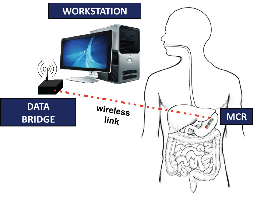
A SMAC-based platform, including the MCR, the data bridge and the workstation
Concerning the hardware, a SMAC-based MCR embeds miniature modules connected together by the developer to accomplish the desired task. Each miniature module provides a distinct functionality, such as wireless communication, powering, digital or analogue sensing, actuation, vision and illumination. These modules are presented in Section 3.1. Bidirectional data communication between the MCR and the workstation is handled by the data bridge, described in Section 3.1.8. Finally, the workstation consists of a Personal Computer (PC), where the user interface is implemented.
Regarding the programming code for the three different subsystems, both the MCR and the data bridge are embedded systems that require dedicated firmware. For this purpose, SMAC provides a three-layer stack, described in Section 3.2. Given this stack of libraries, the developer can implement the main codes to fulfill the specific application requirements. The user interface runs on the workstation and accesses the interface libraries to communicate with the data bridge. As the user interface is strictly related to the specific application, providing details about its implementation is outside the scope of this paper and, therefore, will not be addressed.
An example of an application implementing a robust communication protocol is described in Section 3.3. This example illustrates the interdependencies between the user interface running on the workstation and the firmware codes embedded in the MCR and in the data bridge.
To support the research community in adopting and using SMAC, schematics, PCB layouts, firmware libraries and code examples developed by the authors are open source and available online at http://github.com/SMACproject. This repository also includes guidelines and rules to design new SMAC modules and to integrate them within the existing architecture.
In this section, we provide a description of the SMAC hardware, covering the individual MCR modules in Sections 3.1.1 to 3.1.7, and the data bridge in Section 3.1.8.
Miniature MCR hardware
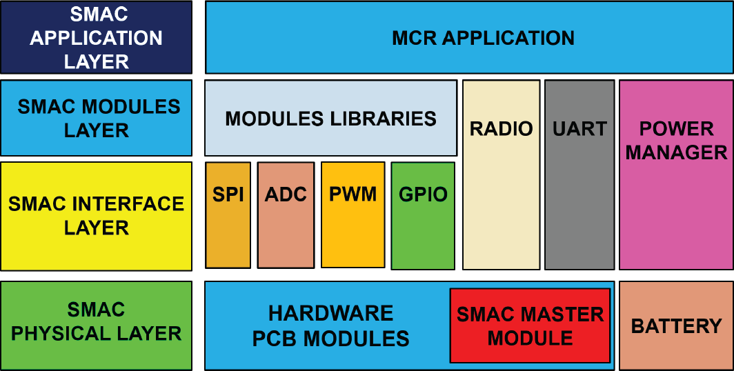
Referring to Figure 2 and Table 1, the 14 SMAC modules developed at the time of writing can be categorized according to six different types: master, digital sensing, analogue sensing, actuation, power management and vision/illumination. For each specific module, Table 1 reports the name, the type, the function, the core IC, the diameter and the current consumption for both active and idle modes (i.e., I ACTIVE and I IDLE , respectively), derived as described in Section 4.2. The maximum module thickness is 1.54 mm. Solderable pads are available on each module for wired connectivity, while the schematics and PCB layouts are provided in the open source repository. It is worth mentioning that user-defined modules can be connected to the master module via one of the communication or data acquisition peripherals, or by using the available GPIO pins. If the developer wishes to replace the master module with a different microprocessor, the other SMAC modules can still be integrated in the MCR, as they are provided with standard connectivity.

The SMAC Modular Architecture. The modules in blue are described in this work and are provided open source, while the modules in orange should be added by the developer.
Main features of the SMAC modules

The master module is the programmable component of a SMAC-based MCR and is also responsible for wireless communication with the data bridge. As represented in Figure 2, other functionalities include data acquisition (directly from a sensor or through a dedicated front end), the generation of control signals for the actuators, and the management of active/idle mode for the other modules. The core IC in the master module is an 8051-based wireless microcontroller (CC2530, Texas Instruments, USA) [37]. It features an 802.15.4 radio transceiver, 8 kB of Random Access Memory (RAM), and 256 kB of flash, GPIO pins, Serial Peripheral Interface (SPI), an eight-channel Analogue-to-Digital Converter (ADC) with a 12–bit resolution, energy management, sensor data processing and Pulse Width Modulation (PWM) generation for actuator driving. The board layout of the master module was designed with 19 solderable GPIOs pads for interfacing with the other hardware components.
Concerning wireless connectivity, the CC2530 IC package comes with two unbalanced output pins that need to match a 50 Ω impedance with a single termination. This matching is typically obtained by passive discrete RF front-ends, consisting of dedicated high-precision capacitors and inductors. However, this is not an optimized solution in terms of the component count and PCB surface required. Therefore, a matching impedance balun low-pass filter was selected (2450BM15A0002, Johanson Technology, USA) for the SMAC master module. The routing from the unbalanced RF pins is symmetrical to the balun, with tracks of the same length and width, thus reducing RF absorptions by working in combination with a ground-shielded plane underneath. Concerning the antenna, it consists of a quarter-wave monopole, obtained by a copper wire soldered nearby the balun on a specially designed pad.
Selecting this specific IC as the core of the Master Module has a double advantage in terms of size. First, a single SMAC module can fulfill both wireless communication and data management functions. Second, the antenna for a 2.4 GHz communication is typically smaller than what would be required if using a lower carrier frequency. On the other hand, 2.4 GHz is very close to the resonance frequency of water molecules and, thus, it is not an optimal solution for devices working inside the human body due to tissue attenuation of the electromagnetic signal. While our previous work shows that the solution proposed here is suitable for feasibility studies and in vivo trials in porcine models [38], the optimal solution when transitioning to design optimization is a carrier frequency in the 433 MHz band [39].
Power management module
The Power Management Module (PMM) provides regulated power from the battery to the rest of the SMAC modules. The PMM (architecture is represented in Figure 3 (a)) allows the developer to use different powering solutions. In particular, this module integrates a Low Drop Output (LDO) to generate a single supply-fixed 3.3 V voltage, providing up to 500 mA of current. The PMM also generates a variable regulated output voltage within the range of 0 V to 3.3 V, and two equal fixed dual-supply ±1.65 V voltages. This module features circuit protection to prevent an incorrect battery connection and Electrostatic Discharge (ESD). The core ICs for this module is a LDO (TPS33, Texas Instruments, USA) and a dual operational amplifier (AD8617, Analog Devices, USA). The PMM also implements a battery monitor by partitioning the battery voltage. This signal can then be connected to an ADC input pin of the master module.

The architecture of the PMM module (a) and the 2AF&ADC module (b), respectively
As reported in Table 1, we have implemented seven different sensor modules with a digital interface to the master module. The master module can configure the sensor and retrieve the data via SPI communication. To save power whenever the application allows, the master module can control the active/idle mode of the sensor via GPIOs connections. The available digital sensing modules at the time of writing – with their SMAC identifier in brackets – include a triaxial accelerometer (3DA), a triaxial gyroscope (3DG), a triaxial magnetometer (3DM), a triaxial accelerometer combined with a triaxial gyroscope (3DAG), a triaxial accelerometer combined with a triaxial magnetometer (3DAG), a full nine-Degrees of Freedom (DOF) Inertial Measurement Unit (IMU) (3DAMG), and a pressure and temperature (PT) sensor. Core ICs, board diameters and current consumptions are provided in Table 1. The sensor configuration and data collections are handled by the interface library described in Section 3.2. If the developer needs to use a different digital module, it can be connected directly to the SPI port of the master module.
Analogue sensing modules
Whenever a 12-bit resolution is acceptable for the specific application, analogue sensors can be connected directly to the ADC embedded in the master module, as suggested in Figure 2. If a higher resolution is required, the SMAC eight ADC module can be integrated in the MCR. This module embeds an ADC (AD7689, Analog Devices, USA) with eight single-ended channels (or four differential), a resolution of 16 bits per channel and a 250 kHz sampling rate.
Another available module – the 2AF&ADC – includes a two-channel analogue front end for conditioning the sensor signals before digitalization. This module features hardware bias correction, double-ended or single-ended sensor interface, gain selection, and single or dual supply operation (± 1.65 V). The block diagram for this module is represented in Figure 3 (b) and consists of low-pass filters and gain selectors for the instrumentation amplifier (AD623, Analog Devices, USA) and a 16-bit resolution ADC (ADS8320, Texas Instruments, USA) [37].
Both analogue sensing modules described in this Section exchange data with the master module via the SPI interface.
Actuation modules
Two different SMAC modules are currently available for driving miniature actuators by reading PWM signals from the master module.
A first board (BSDCC) was designed to drive up to four brushed Direct Current (DC) motors, or four vibrating mass motors, or two step motors. This module integrates a dual full-bridge low-voltage motor driver (A3901, Allegro Microsystems, USA).
A second module – the BSLDCC – is capable of driving up to two brushless motors via two identical ICs (BH67172NUX, ROHM Semiconductor, Japan). This board is also able to read the rotor relative position through Back Electromotive Force (BEMF) feedback, and change the direction of rotation depending on the status of a digital input pin connected to the GPIO port of the master module.
Vision and illumination module
MCR applications may include the use of a vision module [4, 6, 40]. Since the SMAC master module only provides low data-rate wireless connectivity, a dedicated telemetry channel is required for image transmission.
A number of miniature wireless cameras that integrate telemetry are available off-the-shelf, including the CMDX-15, CMDX-23, CMDX-6, CMDX-58 (RF LINKS, USA) [41], and can be integrated within the SMAC platform. Miniature wired camera can be used [42] for prototyping or soft-tethered applications.
Regarding illumination, which is always required for acquiring endoscopic images, we have developed a dedicated module (VI) consisting of a Light Emission Diode (LED) driver (TPS61161, Texas Instruments, USA) and four white LEDs connected in series. LED brightness is controlled by the master module via a PWM signal. The driving current can reach up to 120 mA. This module also includes a digital switch (MIC94044, Microrel, USA) to power the wireless camera. The switch can be connected to a GPIO on the master module. As represented in Figure 4, the VI board comes with an off-centred circular opening (diameter of 4 mm) to accommodate the optics of the camera. Should a larger opening be required, the number of LEDs can be reduced. Extreme care is required in integrating the camera, the illumination and the optics (i.e., in order to avoid image degradation due to reflection and back scattering, the camera needs to be optically isolated from the LEDs).

The SMAC platform hardware modules
The current version of the SMAC data bridge consists of the same wireless microcontroller used in the master module (CC2530, Texas Instruments, USA), a Universal Serial Bus (USB)-to-Universal Asynchronous Receiver/Transmitter (UART) converter (FT232R, Future Logic Devices, UK), and 19 GPIOs available to developers for connecting external peripherals. As represented at the top of Figure 4, the data bridge is a 25 mm × 30 mm × 1.54 mm PCB board that can be powered over the USB connection with the workstation.
Regarding the RF connectivity, the data bridge implements the same circuitry as the master module (i.e., the balun and the quarter-wave monopole antenna). Experimental data reported in Section 4 shows a reliable connection within 2 m of separation distance during in vivo trials. If the wireless link needs to cover a larger range, a power amplifier (e.g., CC2590, Texas Instruments, USA) must be integrated in the data bridge.
The SMAC firmware stack
As represented in Figure 5, the SMAC firmware stack consists of three layers of libraries that build on top of the physical layer. The SMAC interface layer and the SMAC modules layer together constitute the SMAC Hardware Abstraction Layer (HAL). The SMAC application layer is where developers implement the main routine that defines and instantiates the tasks for the SMAC modules.
The SMAC firmware stack
The SMAC firmware stack is written in the ANSI C programming language and can be compiled by any standard C compiler, such as Code Composer (Texas Instruments, USA), IAR Embedded Workbench (IAR Systems, USA) or Eclipse (Eclipse Foundation, CAN) [37, 43, 44].
This layer provides functionalities for the developer to interface the MCR master module, either to the data bridge via radio communication, or to the other hardware modules via SPI, PWM, ADC, GPIOs or UART peripherals. In particular, the SPI interface can be used to configure and receive data from the digital sensing modules or to gather data from the ADC channels in the analogue sensing modules. Actuation can be controlled via the PWM interface or by the GPIOs pins used as ON/OFF switches. Another possible function for the PWM interface is to regulate LED brightness in the illumination module.
As the MCRs are battery operated, the interface layer gives the developer several macros to handle the master module power modes and the battery monitor in the PMM module.
Regarding wireless communication, a dedicated radio library provides macros to configure the 2.4 GHz RF wireless link and set connection parameters, such as security key, RF channel, frequency tuning and device addresses. The radio interface is capable of transferring data within a defined time-out, varying the RF power to save battery lifetime, and measuring the Signal Strength Indication (RSSI). The SMAC radio message, represented in Figure 6, has the IEEE 802.15.4 Physical Layer (PHY)/Medium Access Control (MAC) standard frame [45], with a formatted payload that includes a message header, a package counter, the battery level, a time stamp, the master module core IC temperature, RSSI, the data length, a variable-size data slot, and a message-end code. The maximum data payload is 108 bytes per message. Typically, the SMAC payload contains messages and sensor data in case of communication from the MCR, or messages and commands when travelling in the opposite direction (i.e., from the data bridge to the MCR).
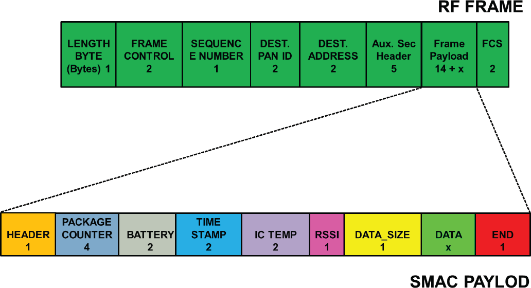
The SMAC radio message and the RF frame descriptor
As proposed in the example illustrated in Section 3.3, the SMAC payload can be used as a shared package across platform subsystems to allow state synchronization. This can be achieved by using a common message syntax, data types, encoding rules and nomenclature. This approach also allows the application to detect the status of data transmission, to check reception errors and to assess data corruption. These features are very useful in notifying the workstation of any possible failure in the MCR.
When the developer is programming the microcontroller in the data bridge, the interface layer provides UART communication with the workstation, as well as radio communication with the MCR and control over the GPIO pins.
This layer provides libraries for each specific SMAC hardware module. These libraries are linked in the SMAC application through a configuration file, which defines the MCR configuration (see examples available in the SMAC repository). Each library consists of primitives for the interface layer to access the internal functionalities of the specific module. These macros can be used to read/write the module registers, access the module GPIOs or operate the core IC. This layer allows the developer to easily reconfigure the MCR in case a hardware module needs to be added, removed or replaced by a different one. Any library describing user custom modules can be straightforwardly integrated in the SMAC modules layer.
The SMAC application layer
The application layer consists of a main routine where the developer implements the MCR application. Inbound commands for the HAL are included here through the macros defined in the configuration file. These commands include sampling, actuation and data transfer through the radio interface to the data bridge. The developer can incorporate into the application layer custom algorithms to accomplish the desired MCR tasks.
A SMAC application example
The application example provided in this section describes a robust handshaking protocol for wireless communication between the MCR and the user interface running on the workstation. This protocol was successfully implemented in [1, 46, 47].
The SMAC application used in this example includes two different firmware codes – one for the MCR and one for the data bridge – that can be represented as two separate FSM diagrams. The FSMs implemented in the MCR and in the data bridge are shown in Figure 7 and Figure 8, respectively, while the FSMs interaction with the workstation is presented in the time-flow diagram in Figure 9. Each of the FSMs consist of six numbered states (i.e., S0 to S5). State transition from a certain state to another for both the FSMs are caused by triggering events, such as condition changes, timer expiration, firmware failures or workstation commands from user input devices (e.g., a keyboard, a joy-pad or a mouse).

Finite State Machine (FSM) diagram for the MCR

FSM diagram for the data bridge

Time flow diagram representing the handshaking protocol among the MCR, the data bridge and the workstation
The three SMAC subsystems, after powering up, are in a BOOT state to configure themselves upon the configuration file settings. For example, the MCR configures the communication interface parameters (i.e., RF and SPI), as well as the embedded hardware modules. When the BOOT completes, the subsystems change their own state according to their FSMs. The MCR switches into the WAIT COMMUNICATION state, the data bridge into the WAIT WORKSTATION ACTIVE state, and the workstation into the WAIT USER COMMAND state. These are passive states in which packages are broadcast from the MCR to the rest of the platform, regardless of an established connection, and the workstation can access the shared payload fields, such as the battery level or the RSSI, or send notification to the user that the MCR has successfully booted up.
In the WAIT COMMUNICATION state, the MCR periodically switches between Low Power Mode (LPM) (i.e., SLEEP and IDLE) and attempts to establish the communication with the data bridge. When the MCR is IDLE, it executes sequentially the following tasks: radio activation, Connection_En message transmission, and reception of the data bridge acknowledgement, the Connect_En. This acknowledgement is accepted only when it arrives within a predefined time frame (typically in the order of a few ms), otherwise a time out event will occur, forcing the MCR back to the SLEEP LPM. This sequence repeats until the communication with the data bridge is established through the Connect_En command, triggered from user input devices. On this event, the workstation and the data bridge change their states respectively to WORKSTATION ACTIVE and BRIDGE ACTIVE, and subsequently, the MCR switches to COMMUNICATION ACTIVE. In the COMMUNICATION ACTIVE state, the MCR has to notify whether the communication was established with all the subsystems (e.g., itself and the workstation). Thus, it replies to the data bridge with the Connect_Ack message and changes its state to MCR READY, waiting for the Ready radio acknowledgement. To guarantee robust handshaking messaging, both the FSMs implement the reception of acknowledgements within firmware time outs. Every time a time out event occurs, no frame is detected and a time out counter is increased. The MCR retries the previous message transmission until the next acknowledge is received, or a Time out Overflow Event occurs, which triggers back the MCR to the WAIT COMMUNICATION state. The same mechanism is implemented by the data bridge which, after receiving the Connect_Ack, changes its state into BRIDGE READY, waiting for the Ready workstation message as shown in Figure 9. Any error in the communication to or from both the MCR and the data bridge forces their states to WAIT COMMUNICATION, while the workstation is notified by error messaging. Once the Ready and Ready_Ack messages are received by all of subsystems, the entire platform waits in the READY state for user input device commands, such as Start, Pause, and Stop.
The user command Start executes the main application, and the command Pause stops its execution and forces each subsystem back to S3, the READY state. In the APPLICATION state, the battery charge level and the RSSI are checked constantly in addition to the RF time out. This improves the robustness and the reliability of the platform by notifying the user if packages get lost, if the battery level is low, or if the RF signal strength is weak. The data flow in the APPLICATION state is bidirectional and the workstation can control the MCR by sending commands for actuators or data for embedded algorithms. Finally, the Stop command forces the subsystems to S5, the CLOSE APPLICATION state, in which the communications are closed. Here, each subsystem ‘falls back’ to the BOOT state after the Quit_Ack message.
We conducted experimental trials aimed to test the reliability and the quality of the wireless connection between the MCR and the data bridge. We also measured the transmission power, P TX , required to establish a connection at different separation distances. We experimentally quantified the current consumption for each SMAC module and we characterized the timing of a SMAC radio message transmission. The MCR's temperature was monitored during an in vivo trial on a porcine model to confirm that the temperature increase was below 1°C.
In Vitro trial
The MCR used for this trial consisted of a master module, a PMM, a PT module and a 50 mAh battery (LP50, Plantraco, CAN). All the modules were enclosed in a rapid prototyped (Objet 30, Objet Geometries Ltd., USA) cylindrical shell (30 mm length, 11 mm diameter). The MCR was submerged in the centre of a 25 cm diameter glass tank, filled with 1.5 l of saline solution to emulate tissue absorption of RF [48]. Weight was added into the shell to achieve neutral buoyancy for the MCR.
The main application for the MCR attempted to establish communication at 14 different levels of P TX , ranging from −18 dBm to 4.5 dBm, and to send pressure and temperature data acquired from the PT module. The data bridge was programmed with P TX at 4.5 dBm. If the MCR received an acknowledgement from the data bridge within a time out period of 5 ms, a confirmation message was broadcast back to the workstation to notify that wireless communication was established successfully for the P TX level used. The sleep time in between consecutive communications was set to 94 ms. The experiment consisted of 100 attempts for each of the 14 transmission power levels, for a total of 1,400 attempts. This test was repeated with the MCR at five different distances from the data bridge (i.e., 0 m, 0.3 m, 0.6 m, 1 m and 2 m).
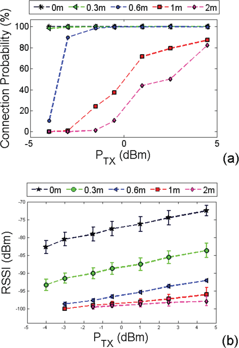
(a) Probability to establish communication with the data bridge at different transmission power levels and distances. (b) The measured RSSI for the message received by the data bridge at different transmission power levels and distances.

Current consumption profile for a master module transmitting a SMAC radio message at full P TX with a 5 ms acknowledgement time out
For P TX below −4 dBm, the connection probability – defined as the number of successful connections over the 100 attempts – was 95% for a 0.3 m distance, but dropped below 10% as the distance was increased. For larger P TX , the experimental results are represented in Figure 10 (a) for the connection probability, and in Figure 10 (b) for the RSSI of the message received by the data bridge.
In order to save power, the developer may want to reduce P TX to the minimum value that still allows for a reliable connection at a certain separation distance. As a guideline, for applications in which the two RF units are within 0.5 m, data can be broadcast with P TX at −4 dBm. If the distance increases up to 2 m, then P TX should be within −3 dBm and 2.5 dBm in order to achieve a connection probability of at least 75%.
The maximum value of the plane wave power density emitted by the MCR was measured in order to compare it with the safety regulations discussed in Section 2.4. Measurements were obtained by a portable field strength meter (8053, PMM, Italy) located in closest proximity to the antenna. The transmission power P TX was set to the maximum level (i.e., 4.5 dBm). The instrument probe was oriented along the maximum radiation direction of the antenna, measuring 0.01 W/m2. This value is considerably lower than the reference levels for general public exposure to time-varying electric and magnetic fields provided in [31].
In order to quantify the current consumption of each SMAC module for both active and idle modes, the voltage drop across a 10-Ω resistor placed in series to the positive voltage supply terminal was recorded with a digital oscilloscope (Tektronix, TDS12014C, USA). The experimental values of I ACTIVE and IIDLE acquired for each module with a voltage supply of 3.3 V are reported in Table 1. It is worth mentioning that the values of I IDLE for the 3D A, 3DM, 3D AG, 3D AM, 3DAMG, PT, 8ADC and 2AF&ADC modules were measured by driving the onboard digital components into low-power mode. Regarding the actuation and illumination modules (i.e., BSDCC, BSTDCC, and VI), I IDLE was measured with no motors connected and with the TEDs off, respectively.
The current consumption of the master module was characterized with the same setup, but with a different protocol. In particular, we focused on analysing the wireless transmission of a SMAC radio message during the APPTICATION state (S4 in the example described in section 3.3). The plot in Fig. 11 shows the single phases of a message transmission and acknowledgement time out expiration with the master module operating at a transmission power P TX of 4.5 dBm and a 5 ms time out. After a period T IDLE the MCR exits from the idle mode and switches on the digital core during T WK After an additional T ON the radio is active and a SMAC radio message with 0 bytes of data is sent during T TX Referring to Fig. 6, the message transmitted in this example consists of 29 bytes (i.e., the RF frame and the SMAC payload with no data) and takes 1.38 ms. If data are transmitted, the T TX period increases by 47 μs per byte sent. Once the radio transmission is over, the master module switches to the radio receive mode for T RX until an acknowledgement is received or the time out expires. In this example, we let the time out expire; thus, T RX is 5 ms. Next, the radio and the core switch off during T OFF , and the master module goes back to idle mode. This example can be generalized considering that T IDLE is decided by the user depending on the level of responsiveness required by the MCR for the specific application, and that T ON or T OFF can be expanded in case of sensor data acquisition or actuator operation (both actions that typically do not require the radio in active mode). The experimental values of current consumption for each specific state of the microcontroller are I IDLE — 9 μA, I WK = 5.8 mA, I ON = I OFF = 12.9 mA, I TX = 36 mA, and I RX = 26.3 mA. It is worth mentioning that these values deviate from what is reported in the data sheet [37] by less than 2%.
As detailed in [38], the battery lifetime can be estimated by using the following average current consumption:

where I t and T i are the current consumption and the time interval related to a single action performed by the MCR within a periodic operation. Considering a worst case scenario of no sleep between consecutive message transmissions (i.e., T IDLE null), 29.69 mA is the average current drained by the master module in the example of Fig. 11.
Equation 1 can be used to predict I for a generic MCR by including the current consumption values reported in Table 1 for the specific SMAC modules composing the MCR, and by considering the time periods when each module is active or idle. Once I is available, the battery lifetime in hours can be estimated simply by dividing the battery capacity - typically provided in Ah (Ampere-hours) - by the average current consumption.
The reliability of the wireless connection and the temperature behaviour of the same MCR described in Section 4.1 were assessed in vivo on an anaesthetized porcine model. The porcine surgery was performed at Vanderbilt University under IACUC protocol M/14/014. A 56 kg female Yorkshire swine was used for this study. After intravenous sedation, an overtube (Guardus Gastro, US endoscopy, USA) was placed in the upper GI tract to facilitate the endoscopic introduction of the MCR into the stomach.
In this case, the wireless connectivity test was focused on pressure and temperature data streaming from the MCR to the data bridge at different levels of P TX and different distances of the data bridge from the animal. The communication protocol described in Section 3.3 was adopted, and 200 bytes of payload were transmitted for each value of P TX (range: −4 dBm, 4.5 dBm) and distance (0 m, 1 m, 2 m, and 3 m). The application implemented error checking to notify the workstation for missing packages. A package was considered lost after three transmission retries. The experimental results are presented in Figure 12.

Percentage of lost packages during the in vivo trial
The minimum RSSI needed to achieve a package loss below 20% was −86.9 ±0.62 dBm at 0 m with a P TX of −4 dBm, −98.21 ±0.34 dBm at 1 m with a P TX of 1.5 dBm, −98.57 ±0.55 dBm at 2 m with a P TX of 2.5 dBm, and −99.19 ±0.48 dBm at 3 m with a P TX of 2.5 dBm.
With a P TX of 2.5 dBm, we were able to achieve a package loss below 20% within 2 m of the animal. In this configuration, the average current consumption of the MCR during data broadcasting was 25.9 mA. Considering the main application data streaming frequency of 166 Hz, the MCR was able to transmit data for 110 minutes with a 50 mAh battery.
Regarding the thermal behaviour of the MCR, the temperature acquired by the PT module reached a plateau of 37°C within about 10 minutes after introducing the capsule into the stomach of the animal. Afterwards, the recorded temperature variation was within 0.6°C.
In this section, we provide a brief description of three different SMAC-based MCRs recently developed by the authors. In addition, we list a number of other MCRs described in the literature that can easily be implemented via the SMAC approach. All of these MCRs are listed in Table 2, together with the SMAC modules required to implement them.
SMAC modules required to implement the MCRs reported in the literature
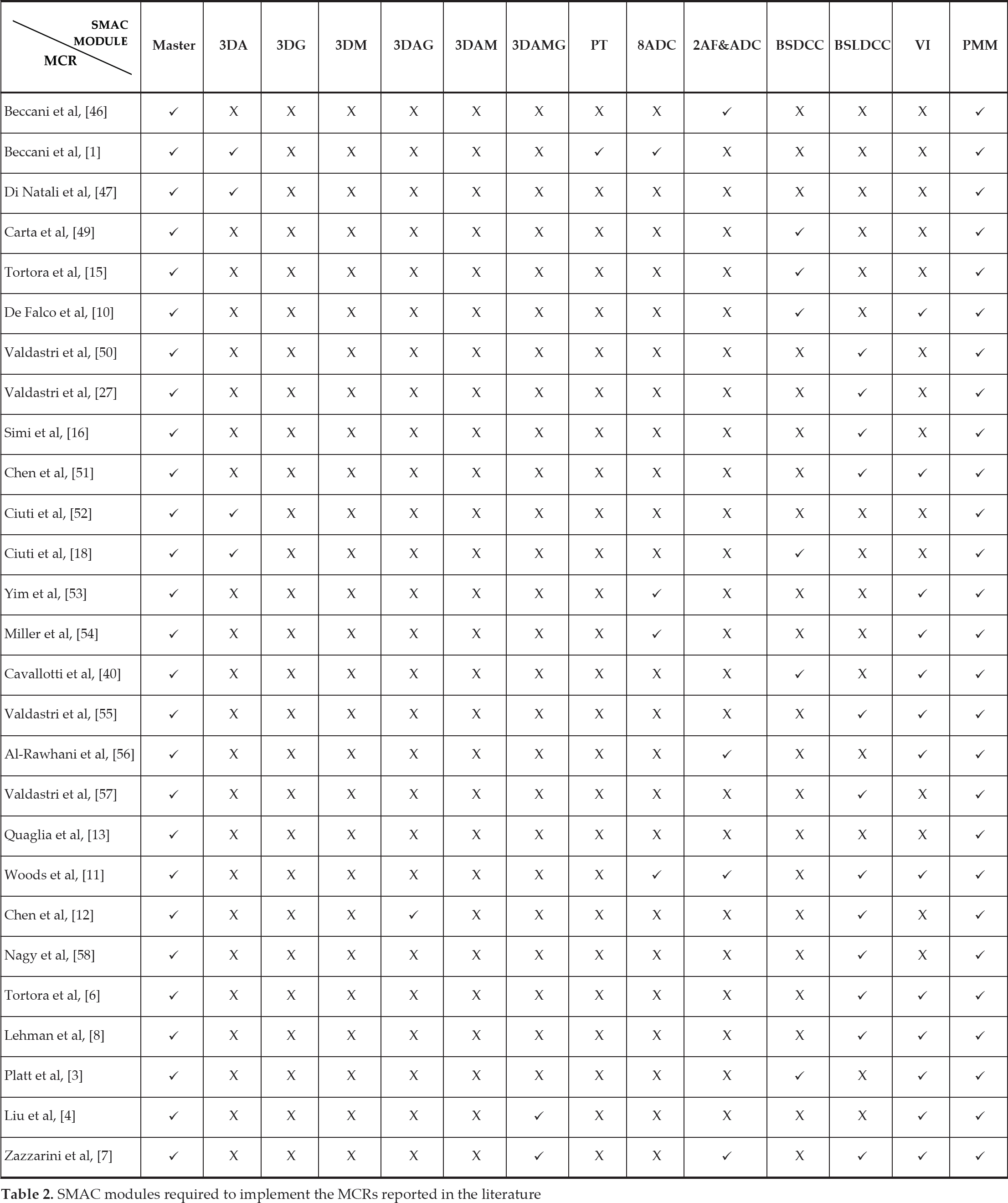
SMAC modules required to implement the MCRs reported in the literature
While this analysis is not intended as an extensive review of the field of MCRs, it clearly shows the flexibility and the potential impact of the proposed modular approach.
In [46], we showed the feasibility of a single DOF Wireless Tissue Palpation (WTP) to identify hidden tumoural masses inside the liver during MIS. The proposed approach consisted of a wireless probe – the MCR for this particular application – that was deployed into the abdomen through laparoscopic access. The MCR in this case was manipulated by an external magnetic field to palpate the liver at different points on the surface. To measure the tissue indentation, the MCR embedded a 3DA module and an analogue mono axial Hall effect sensor, connected to a 2AF&ADC module. High accuracy was required to sample the Hall effect sensor in order to reconstruct the indentation depth with sub-millimetre accuracy. Master and PMM modules were also included in the MCR.
For this application, the SMAC payload was composed of 20 bytes. Each dataset required an acquisition time of 3.1 ms, while the workstation program had a refresh time of 6 ms. The device current consumption was 70 μA in low-power mode, increasing to an average of 33 mA during data streaming. The battery lifetime was about 100 minutes.
Surgeon-operated wireless tissue palpation
A different approach to WTP was presented in [1]. In this case, the MCR was designed to be grasped by a laparoscopic instrument and directly operated by the surgeon. Thanks to the modularity and the reconfigurability of the SMAC approach, the time required for redesigning the MCR was minimal. In this case, the MCR had to measure the device position and orientation in six DOFs with respect to an external magnetic field source. The MCR consisted of three Hall effect sensors mounted on a custom structure, two 2AF&ADC modules, a 3DA module, a PT module and a PMM module. All of sensing modules were connected via the SPI interface to the master module, using a data transfer rate of 1 Mbit/s.
The payload was composed of 28 bytes, the data acquisition time was 3.7 ms, and the application refresh time was 5 ms. The MCR power consumption was 200 μA while trying to establish a connection and 24 mA during sensor data acquisition. The average current consumption for each payload transmission was 33.3 mA. The resulting battery lifetime was 88 minutes.
Measurement of resistant properties in the GI tract
The order of magnitude of the resistant force that must be exceeded in order to move a WCE in the GI tract is an interesting parameter for the MCR research community. In [47], we designed an MCR based on SMAC to measure this parameter in an in vivo porcine model.
In this case, the MCR was magnetically coupled with an external permanent magnet and was able to acquire inertial and magnetic field measurements to determine in real-time its motion profile (i.e., position, velocity and acceleration) and the inter-magnetic force. The MCR embedded a custom analogue force and motion-sensing module, integrating six Hall effect sensors and a 3DA module. The master module acquired the Hall effect sensor readings with the embedded ADC, and communicated with the 3DA module via the SPI interface. The PMM was also included in the MCR.
Sensor data were bundled for wireless transmission every 4.4 ms in a 32-byte package. The refresh rate at the workstation was 6 ms. To save power, the MCR sensing front-end was operated in low power mode whenever data acquisition was not required, thus achieving a current consumption of 400 μA. This increased up to 20 mA during data acquisition, and to 48 mA for each payload transmission. The battery lifetime was 75 minutes.
Overview of MCRs that can be implemented via SMAC
Other examples of MCRs published so far that can be implemented via the SMAC approach range from WCEs, which can swim in a water-filled stomach [10, 15, 49, 50], or crawl inside a colon [16, 27, 51], or be manipulated by external magnetic fields inside the GI tract [18, 52–54], or perform advanced imaging [40, 55, 56], or execute a therapeutic function inside the intestine [11, 13, 57]. The modular robotic endoscope for colonoscopy recently reported in [12] can also be implemented via SMAC.
Additional examples can be found in the field of MCRs for MIS or NOTES, such as the wireless modular robots reported in [58], the soft-tethered robots described in [6] that use a wired connection just for powering, the bimanual robot introduced in [8], the wireless laparoscopic cameras described in [3, 4], or the soft-tethered one in [7]. All of these MCRs can be deployed through a surgical incision or a natural orifice and used without the need for a dedicated entry port. This has the potential to reduce the number of incisions required for an abdominal surgery, thus decreasing the potential for surgical site infection and improving aesthetic outcomes.
All of these MCRs are listed in Table 2, together with the SMAC modules that would be required to implement them.
Conclusions and future work
In this work, we introduced for the first time SMAC, an open source platform to foster the development of MCRs. With its modular and reconfigurable approach, pursued at both the hardware and firmware levels, the platform gives the MCRs research community a number of constitutive bricks that can be assembled together to obtain different functionalities. This approach has the potential to lower the barriers to design space exploration in terms of the effort and skills required, thus allowing a wider community to experiment with novel MCR designs.
Our main contribution is ready-to-use modular hardware in the form of miniature, round boards, accompanied with a highly reconfigurable and open source software stack. The low power operation, safety and reliability of wireless communication were experimentally assessed via in vitro and in vivo trials. Aside from what is currently presented in this paper, developers will be able to implement additional modules and to integrate custom solutions into the SMAC architecture by following the guidelines posted in our open source repository. This will expand the component libraries and provide even further support to the MCR design community.
In terms of the limitations of the current platform, better physical connectivity between the modules must be implemented to improve reliability and further reduce the effort required to assemble a specific MCR. Currently, the authors are exploring flexible and magnetic connectivity to address this issue.
Wireless connectivity for the SMAC modules across biological tissues is limited to 2 m. This is typically sufficient for exchanging data between a MCR inside the body of the patient and the data bridge in close vicinity. If a larger distance needs to be covered by the wireless communication, a power amplifier must be integrated in the data bridge, as mentioned in Section 3.1.8.
Future work will aim to extend the SMAC libraries to include additional microprocessors, sensor and actuator modules, and wireless transceivers implementing different communication protocols and carrier frequencies (e.g., Low Power Bluetooth, 433 MHz).
Footnotes
7.
This material is based upon work supported by the National Science Foundation under grant number CNS-1239355. Any opinions, findings and conclusions or recommendations expressed in this material are those of the authors and do not necessarily reflect the views of the National Science Foundation.