
Abstract
Information system change is concerned with deliberate modifications to an organization's technical and organizational subsystems that deal with information. Changes result in adjustments being made to the configuration of information systems that could have an impact on the operations of those systems. This paper examines the problem of interference between old configuration activities, new configuration activities and reconfiguration activities that occur due to overlapping modes. The paper proposes a novel form of depicting and solving the problem based on a flow-based conceptualization in which a configuration can be viewed as a system of flow systems organized architecturally, described by their internal flows, and connected by external flows and triggering. This method of diagramming is applied to a complex case study involving the reconfiguration of an office workflow for order processing described in BPMN. The diagrams resulting from this method and the BPMN diagrams are then examined side by side. Accordingly, the conclusion is that a new high-level representation seems more systematic as a foundation for building a conceptual schema of business processes.
1. Introduction
The ancient Greek philosopher Heraclitus is quoted as saying, “Everything changes and nothing stands still.” The phenomenon of change applies to organizations and their information systems. Information system (IS) change is concerned with deliberate modifications to an organization's technical and organizational subsystems that deal with information [1]. According to Magalhaes [2], “IS implementation is a (never-ending) process of change.” An organization must make frequent changes to its IS in order to update hardware and software components, fix software flaws and other errors, address security threats, and adapt to changing business objectives.
These constant changes result in adjustments being made to the configuration of IS; hence, they could have an impact on systems' operations. “Configurations can be complex, often involving state, and they are expressed in a plethora of languages which differ not only by syntax, but also by semantics and domain” [3]. The notion of configuration is applied in diverse contexts such as hardware, software, and theoretical computer science. In Turing's machine, “the configuration determines the possible behaviour of the machine” [4]. Software configuration management is concerned with assembling software applications systems from component parts with a focus more on change management [5]. As systems change, the configuration specification determines aspects that may vary when the system is reconfigured.
Note that this configuration conception is different from what is called configuring software package servers and data files that support diversity in applications. This latter type of configuration refers to a repository containing different versions of an application, and the configuration specification may simply define which version is installed on a system, e.g., a machine. This paper is concerned with schematic configurations involving structural changes having to do with activities and their precedence [6] resulting from changing configuration requirements and bringing a system into compliance with those requirements (reconfiguration). Examples of structural changes include the deletion of an activity, the addition of a precedence relation between two activities, and the parallelization of two activities [6]. Reconfiguration necessitates first changing the global conceptual view; in an analogy to programming, this schematic reconfiguration entails changing the program flowchart as a first step in modifying the program in response to a change in its requirements.
The aim of schematic reconfiguration is to minimize changes, limiting them to the reconfigured portion of the system. For example, it is possible to clone the entire software system, modify it, then switch to the new system, or we can follow the approach, as we do in this paper, of developing a new subsystem as an independent subsystem, pasting it to the running system, testing its behaviour, then switching to the partially modified system.
Configuration and reconfiguration specifications can be described at different levels of abstraction, with transformations ranging from high- to low-level specifications. A high-level representation specifies the overall configuration of a system. This paper focuses on a diagrammatic high-level description as a tool in maintaining a system's configuration and reconfiguration. Visualizing the configuration of a system decreases the time required to diagnose and repair failures [7].
1.1 Problem
Adjustments made to the configuration of information systems can have an impact on systems' operations. The problem of the reconfiguration of IS is difficult, highly visible and costly [8]. Many organizations suspend work in progress in order to avoid the undesirable side effects of complex changes, but sometimes it is impossible to shut down all activities in order to make changes [6]. Accordingly, “The problem of interference between old configuration activities, new configuration activities and reconfiguration activities that occurs due to overlapping modes needs to be addressed” [9].
Generally, in software systems, local changes can have global effects [10], and many examples can be given in this context [7], e.g., a 2011 outage in Amazon Web Services [11] and a 2010 outage in Facebook [12] were each a disaster caused by a configuration change.
The need exists for better understanding of system configurations, provided by tools for explanation, visualization, and the repair of high-level processes instead of low-level program code [10].
1.2 Solutions
The problem mentioned above is typically discussed in the context of how to build dependable systems that operate in dynamic environments. Dependability is “the ability of a system to avoid failures… and outage durations” [13]. Two of the basic characteristics of dependable service are flexibility and availability, made possible through dynamic reconfiguration. Dynamic reconfiguration aims at making software systems highly available, maintaining their consistency, and minimizing the down-time caused by reconfiguration [14].
Reconfigurations can be instantaneous or non-instantaneous; in the latter case, system service is discontinued during the reconfiguration process. According to Abouzaid et al. [9],
[Instantaneous reconfigurations] are unrealistic in the service domain. For example, instantaneous mode change in a distributed system is generally not possible, because the system usually has no well-defined global state at a specific instant (due to communication delays). Also, waiting for the reconfiguration to complete is not acceptable if (as a result) the environment becomes dangerously unstable or the service provider loses revenue by the environment aborting the service request.
Accordingly, the need exists to study the problem of dynamic reconfiguration of dependable services, especially on its formal foundations of modelling and verification [9].
Dynamic reconfiguration enables resources to be added or removed while the system is running [15]. It “can provide maximum flexibility of the system by replacing one configuration by another at runtime. Furthermore, it makes the system more dependable because the overall architecture of the system has not been changed by adding or removing configurations” [16].
Extensive research and development has been conducted on handling this problem [9, 17–19]. Run-time testing of configurations is valuable; it also has weaknesses and may require an “extensive complex virtualized infrastructure” [3]. In the static analysis of configurations, they are treated as mathematical artefacts with automated reasoning. Analysis is limited by the mathematical model of the system, and most static analyses do not catch low-level errors. A scenario-finding technique provides specific instances of the behaviour of a configuration. Furthermore, software modelling helps to facilitate understanding of the specifications, constraints, and alternatives [3]. “Specification languages like UML benefit from scenario-finding to help bridge concrete and abstract representations” [3].
This paper utilizes a flow-based conceptual description to solve the problem of dynamic reconfiguration. Here a configuration is viewed as a system of flow systems organized structurally (e.g., a nested structure); these are described by their internal flows and connected by external flows and triggering (see Figure 1; flows and triggering are represented by solid and dashed arrows, respectively). The resultant systematic representation can provide a foundation for building a conceptual schema of business processes and their relationships.

A configuration based on a system of flow systems
In such a proposed scheme, a change in configuration (reconfiguration) means a change in flow systems, structural change (e.g., eliminating a flowsystem), or a change in flow. The overall configuration is similar to the blueprint of a building, where the reconfiguration of flow involves changes made by adding new units, and by changing flows, e.g., the movement of people and things, flows of water and electricity, gas, communications, etc.
As an introduction to this technique of flow-based description, the next section provides a brief overview of the background and features of the proposed model, called the Flowthing Model [20–23]. The specific example developed in this paper is a new contribution.
2. The Flowthing Model
The foundation of the Flowthing Model (FM) can be related to the notion of fluidity propounded by Heraclitus, a pre-Socratic Greek philosopher who declared that “everything flows.” Plato explained this as, “Everything changes and nothing remains still,” where instead of the word “flow” he used “change”.
2.1 Description of FM
In FM, things that “flow” (called flowthings, denoted by solid arrows in the FM diagram) are things that make their appearance in a system within their spheres. If a system (global sphere) includes a human sphere, then this human sphere has subspheres such as actions, money, information, emotions, etc. as flowthings. These flowthings flow in specific “flow channels,” changing in form and interacting with outside spheres. The lower-level spheres where the flows occur are called flowsystems; these include, at most, six stages (states of a flowthing), as follows:
Arrive: a flowthing reaches a new flowsystem
Accepted: a flowthing is permitted to enter the system. Note that, in FM, if arriving flowthings are also always accepted, Arrive and Accept can be combined as a single
Processed (changed in form): the flowthing passes through some kind of transformation that changes its form but not its identity (e.g., compressed, coloured)
Released: a flowthing is marked as ready to be transferred (e.g., airline passengers waiting to board)
Created: a new flowthing originates (is created) in the system (e.g., a data-mining program)
Transferred: the flowthing is transported somewhere outside the flowsystem (e.g., packets reaching ports in a router, but still not in the arrival buffer).
These stages are mutually exclusive; i.e., a flowthing in the process stage cannot be in the created stage or the released stage at the same time. An additional stage of stored can also be added to any FM model to represent the storage of flowthings; however, storage is a generic stage, not exclusive, because processed flowthings can be stored, as can created flowthings, and so on.
Figure 2 shows the structure of a flowsystem and its internal flows with the six stages and transactions among them, assuming the irreversibility of flow, e.g., released flowthings flow only to transfer. A flowsystem may not need to include all the stages; for example, an archiving system might use only the stages arrive, accept, and release. Multiple systems captured by FM can interact with each other by triggering events related to one another in their spheres and stages.

Flowsystem
FM uses the following basic concepts:
2.2 Example: FM version of a Simple BPMN Mode
Analysing a hotel reservation scenario, Zhou [16] builds a BPMN-based graphical description of a hotel booking process in which a hotel receives a reservation request, checks the availability, and finally, based on that, either rejects or confirms the request (see Figure 3). Figure 4 shows the corresponding FM representation. It includes three flowthing types: request, rejection, and confirmation, each with its own stream of flow across different flowsystems in the customer and hospital spheres. The figure is a type of map, like the map of a city showing streets, buildings and facilities. A reservation request is created in the customer sphere (circle 1 in the diagram). It flows to the request flowsystem in the hotel sphere (2), where it is received and processed (3). The process results in triggering (4) the creation of either a rejection (5) or a confirmation (6) that flows to the customer. Details of constraints, synchronization, timing, etc., can be superimposed on the diagram, just as details for managing traffic can supplement a city map.
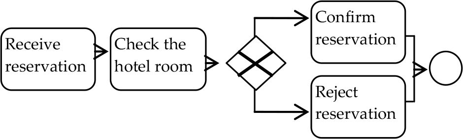
BPMN representation of the Hotel Reservation Scenario (redrawn from [16])

FM representation of the Hotel Reservation Scenario
Note how continuity in the narration of possible flows has forced the addition of the customer side of the “story” to complete the scenario. Different flowthings (data types) are separated into different streams of flow, each specific to its own realm of creation, movement, and destination. There are no unbounded natural language operations such as check, confirm, reject, etc., rather, only five operations –create, release, transfer, receive, and process – that are rhythmically repeated in all flowsystems.
3. Complex case study
Abouzaid et al. [9] use BPMN to describe a “complex case study” involving the reconfiguration of an office workflow for order processing. They then use different formalisms (VDM, a model-based formalism; π, calculus and process algebras) to model the design and study reconfiguration requirements. “This evaluation may be useful to system designers intending to use formalisms to design dynamically reconfigurable systems, and also to researchers intending to design better formalisms for the design of dynamically reconfigurable systems” [9].
This case study has been studied in several works, including [6, 9, 16, and 24]. It describes the dynamic reconfiguration of an office workflow that processes orders from customers in a number of activities, in the following sequence:
Receipt of order
Evaluation
Rejection/acceptance:
If the order is to be processed, then the following tasks are performed concurrently:
Billing: the customer is billed for the total cost of the goods ordered plus shipping costs.
Shipping: the goods are shipped to the customer.
Archiving
Confirmation
After some time, it is decided “to change the order processing procedure, so that Billing is performed before Shipping” instead of concurrently [9].
A version of this problem was analysed by Ellis et al. [6] using Petri net formalism based on what they call “sequel flow nets,” as shown in Figure 5.
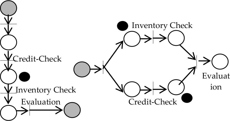
Different configurations described in Petri net (from [6])
This paper focuses on the problem presented by [9] in a design utilizing Business Process Modelling Notation [BPMN] for an office workflow case study [25]. BPMN was selected for comparison with FM because of its wide adoption as a standard for business process modelling [26].
Accordingly, Figures 6 and 7 show a partial view of the original, and a new configuration, respectively. Only partial views are shown because we focus on the portions related to the reconfiguration problem. Additionally, the aim of this paper is not to produce an exhaustive or definitive description of Abouzaid et al.'s [9] design scheme; rather, the intent is to show only details sufficient to facilitating the objective of the paper: to contrast the diagrammatic representation of BPMN against our model of reconfiguration of the design of the office workflow case study.

Partial view of office workflow – BPMN diagram of the original configuration (From [9])

Partial view of office workflow – BPMN diagram of the new configuration (from [9])
Figure 6 includes three pools representing the functional entities of main, bill, and ship. In the main pool, when the order is received, the bill and ship activities are called concurrently by means of a parallel gateway. “The same gateway is used to merge the results from Bill and Ship. The bill and ship details are then sent to the caller (Office Workflow)… for the sake of simplicity and readability of the overall workflow, we assume that neither the billing activity nor the shipping activity provides a negative result” [9].
In Figure 7, the parallel gateways have been removed, and according to [9], the reconfiguration requires a change in the main lane only “where the billing and shipping activities are called, and therefore their invocations ordered, while the rest of the workflow remains unaltered.”
Now, how can the transition from the original configuration to the new one be accomplished? Figure 8 shows a redrawing of the overall workflow during its reconfiguration.
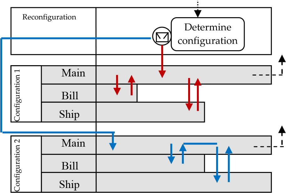
Partial view of office workflow – BPMN diagram of the reconfiguration (based on a diagram in [9])
Abouzaid et al. [9] also introduce an alternative overall workflow during reconfiguration, as shown in Figure 9, where the bill and ship pools are separated from the region of reconfiguration. However, they opted to use the first design (Figure 8) for a “technical reason where two outputs cannot be in sequence.”

Partial view of an alternative BPMN diagram of the reconfiguration (based on a diagram in [9])
The default flow is made to the original configuration. “This default flow can be altered through an interrupting message event contained in a ‘determine configuration’ activity, an activity that determines which configurations should be used” [9]. An authority can be placed in charge of deciding the reconfiguration.
It can be presumed that the solid arrows in the BPMNbased Figure 10 may represent pure “control flow.” For example, “Receive ship details” in the new Figure 6 activates “Send bill and ship details,” even though there is no direct connection between “Receive bill details” and “Send bill and ship details” as shown in Figure 10.

Illustration of pure control flow in the BPMN diagram.
4. FM-based Modelling
4.1 The original view of office workflow
Figure 11 shows the FM representation that corresponds to the BPMN workflow diagram of the original configuration in Figure 6.

The FM representation of the original configuration.
FM includes “real” data flow represented as solid lines in the representation. Accordingly, so orders can be sent in parallel, the flowthing order includes the original order and its copies. How else could we send an order concurrently to bill and ship? FM conceptualizes the order and its copies as being of the same type of flowthing, just as even and odd are types of integers in a programming language. Consequently, we do not need to separate the flows of the original order and its copies.
In Figure 11, the four flowsystems in the lower/middle part of the figure are in the main sphere: main/order, main/ship details, main/bill calculation, and main/sending. For the sake of simplicity and compactness, the box around these flowsystems is not drawn. An order flows to the main/order flowsystem (circle 1 in the figure). It is processed, triggering (2) the creation (3) of two copies, Copy A and Copy B (4 and 5, respectively).
Copy A flows to the Bill sphere (6), where it is processed (7) to trigger (8) creation (9) of the bill calculation that flows to its flowsystem in main (9). In the main/bill calculation flowsystem, the bill calculation data is processed (10) and triggers the creation (11) of the report, including bill calculation and shipping details, which flows to the office workflow.
Copy B (5) flows to the ship sphere (12) to be processed (13) to trigger (14) the generation (15) of shipping details that flow to main (16), where copy B is processed (17) and flows (18) to trigger the creation (11) of the report that includes bill calculation and shipping details.
Figure 12 depicts the new configuration. It shows that copy B of the order is blocked (the dark bar – can be implemented as an ‘if statement’ inside the FM stage) in the release stage (circle “a” in the figure). When the Bill calculation arrives (“b”), this triggers (“c”) clearing the flow of copy B to ship (“d”).

The FM representation of modification in the new configuration
Figure 13 shows the FM overall workflow during reconfiguration. An order is received (circle 1) by the reconfiguration selection flowsystem (2, the long flowsystem on the right side of the figure). The received order is processed (3) to determine whether it flows to the parallel procedure of bill and ship (4) or the sequential procedure (5). The default flow can be altered by interrupting the process stage with a triggering signal (6) to determine which configurations should be used.

The FM representation of the reconfiguration
5. Discussion
BPMN and FM can be contrasted and compared at two different levels: the overall model and the level of technical details.
5.1 Some remarks on the BPMN and FM representations
Contrasting the FM representation of Figure 11 with the BPMN modelling (Figure 6), it can be noted that the sequence flow in BPMN (solid arrows) may or may not subsume the message flow (dashed arrows). For example, in Figure 6 the “Receive order”, parallel gateway, and “Call bill” are connected by solid arrows representing the sequence of execution. It is understood, implicitly, that the order is also flowing in the same direction. The same BPMN representation can depict two situations: one in which the control flow coincides with the data flow, and one where they do not, e.g., a message arrives, activating a sequence of processes that do not use the message. Additionally, there is an implicit “jump” in message (data) flow, as illustrated previously in Figure 10.
In FM, the semantics of flow are clear. The flow of data implies a possible chronological sequence. If a piece of data moves from one sphere to another, it is received (after transfer) sometime after it is sent (released/transferred). Additionally, one clear weakness of BPMN representation is the infinite number of processes that can be specified, e.g., in Figure 6, receive, call, calculate, send, ship; in principle, all natural language verbs could be used to denote activities, whereas FM uses only six generic “processes.”
5.2 General comparison, BPMN vs. FM
The Flowthing Model presents an alternative conceptual representation for use in the context of change during reconfiguration activities. FM-based description concentrates on identifying flowthings and their flows. In FM, flowthing movement (solid arrows) is a fundamental characteristic that denotes an actual or logical flow. The structure of the FM representation reflects a map of the system, in the same way a blueprint serves as the map of a high-rise construction project. By contrast, the BPMN depiction has a prevailing “control flow” distinction that reflects, in general, the network (e.g., sequence) of tasks to be performed; e.g., in the construction analogy: import material, calculate cost, lay foundation, pour concrete, etc.
Accordingly, this implies that an FM schema precedes and is more basic than the BPMN scheme.
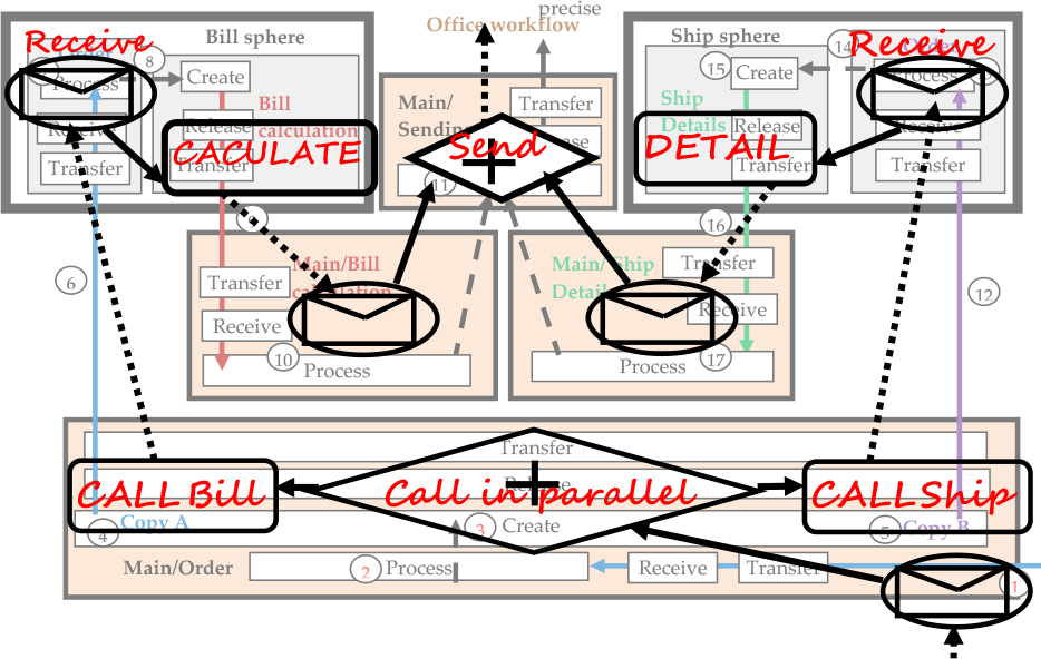
Figure 14 shows the superimposing of the BPMN original configuration of Figure 6 over the corresponding FM schemata of Figure 11. In Figure 14, the BPMN designations and symbols seem heterogeneous (e.g., shapes, icons, text, etc.) over the FM map. If the purpose of such “shorthand” diagramming of BPMN is to make “easier the communication and coordination between non-technical and technical users by offering a common language” [27], the FM description can be simplified as shown in Figure 15.

Simplified FM representation of the original configuration
6. Conclusion
This paper has applied an alternative representation of workflows to the problem of dynamic reconfiguration in the context of business processes. A new solution to the problem is not introduced; rather, the paper proposes a novel form of depicting the problem and its solution.
It is difficult to prove technically that a certain diagramming method is better or worse than another, especially if they are at the same level of abstraction. One way to achieve a reasonable comparative analysis is to apply the same problem to both methodologies and then inspect the resultant diagrams side by side.
Accordingly, the opinion expressed in this paper is that FM representation seems more systematic as a foundation for building a conceptual schema of business processes and their relationships. This observation can be made throughout the paper in the “sketchiness” of the BPMN diagrams, ambiguity in their connections, and excess kinds of activities, e.g., almost any English verb is used. While such an observation is not a conclusive result, FM is potentially worth pursuing to facilitate modelling in this area of application, because it may lead to more precise tools, and it improves understanding of modelling notions (e.g., differences and combinations of types of flows: control flow, data flow, triggering).
Future work may explore the possibility of enhancing the two models with each other. For instance, the basic notions of FM can be injected into workflows, or the rich constructs of workflows can be incorporated into FM.