
Abstract
In this paper, an optimal reconfiguration control scheme is proposed for a quadrotor helicopter with actuator faults via adaptive control and combined multiple models. The combined models set contains several fixed models, an adaptive model and a reinitialized adaptive model. The fixed models and the adaptive model can describe the failure system under different fault conditions. Moreover, the proposed reinitialized adaptive model refers to the closest model of the current system and can improve the speed of convergence effectively. In addition, the reference model is designed in consideration of an optimal control performance index and the principle of the minimum cost to achieve perfect tracking performance. Finally, some simulation results demonstrate the effectiveness of the proposed reconfiguration control scheme for faulty cases.
1. Introduction
In exhibiting open-loop, unstable, dynamic characteristics, the quadrotor helicopter poses challenges for researchers and several significant results have appeared in the literature [1–5]. In designing a controller for this emerging aircraft, there are several important considerations. Numerous sources of uncertainty may appear in the operating system, such as actuator degradation, external disturbances, potential time delays, and so on. These problems may be amplified in the case of actuator faults whereby the helicopter loses its control effectiveness. Many control approaches have been investigated to solve these problems, such as backstepping control [6], sliding mode control [7], LQ control [8] and neural network control [9].
For flight control system reconfiguration there are many methods and more applications in various fields. Its control object is to compensate the change in dynamic performance resulting from actuator faults, which can be supplemented by the redundancy of the effective control mechanism. Various reconfiguration control techniques and strategies have been the focus of many investigations [10–17]. A. J. Calise proposes a developed reconfiguration control law for the X-36 tailless fighter aircraft and offers some results [12]. In this paper, we consider the reconfiguration control of a faulty quadrotor helicopter and put it into application.
In a flight control system, faults may occur such that the corresponding parameter jumps are huge, and thus large transient tracking errors are caused by the large parameter error. Thus, an adaptive control law may take a relatively long time to compensate the uncertainties caused by the actuator failures if the control law is simply based on a single-model design. A multiple models approach is utilized to cover the parameter region. Each model can match a type of fault and the closest model is chosen to describe the current faulty system. Actuator and sensor failure compensation via multiple model-based adaptive control is investigated by P. S. Maybeck [18]. C. Tan applies a multiple model-based adaptive actuator failure compensation scheme for the control of near-space vehicles [19]. Other compensation control schemes based on multiple models have been employed by other researchers [20–25].
In this work, an optimal reconfiguration control scheme via multiple models is studied for a quadrotor helicopter with actuator failures. Mathematical models of the helicopter in terms of rotation and position are analysed based on various physical dynamics and assumptions. In reference to the model design, the optimization of the original control system is conducted via the principle of minimum cost and the optimal performance index has the minimum value simultaneously. The design of the reconfiguration control law is shown in the corresponding part. The proof of its stability is also presented to ensure good tracking capability. Several fixed models can cause the faulty system to track the reference model instantly, while the transient performance can be improved by utilizing the adaptive model. However, if the error in the initial parameters is relatively large, the convergence time of the adaptive model may be longer. Thus, a reinitialized adaptive model is also designed for the faulty helicopter and the system can choose the initial model closest to the current system, which increases the rate of convergence.
The remaining parts of the paper are organized as follows. Aircraft modelling and analysis are introduced in Section 2. In Section 3, the control law is designed in view of reconfiguring the faulty system, followed by proof of its stability. In Section 4, the optimization design of the reference model is presented. The combined multiple models set and some modifications are described in Section 5. Section 6 presents the simulation results. Finally, conclusions are drawn in Section 7.
2. Control Problem
2.1 System Description
The quadrotor aircraft is controlled by the angular speeds of four electric motors, as shown in Figure 1. Each motor produces a thrust and a torque, whose combination generates the main thrust, the yaw torque, the pitch torque and the roll torque acting on the quadrotor. Compared with conventional helicopters, quadrotors do not have a swashplate or constant pitch blades. Therefore, varying the angular speed of each rotor can obtain the pitch and roll control torques. Figure 1 shows the framework of the quadrotor helicopter.

Framework of the quadrotor helicopter
The mathematical model described in this part relies upon the following assumption:
2.1.1 Modelling of the rotation
The thrust generated by each propeller can be modelled as a first-order system described by:

where u is the PWN input to the actuator, ω is the actuator bandwidth and K is the positive gain. A state variable, v, is used to represent the actuator dynamics and is defined as:

Two propellers contribute to the motion along each axis. The rotation around the centre of gravity is produced by the difference in the generated thrusts. The roll/pitch angle θ can be formulated using the following dynamics:

where:

denoting the rotational inertia of the device along the roll and pitch axes. L is the distance between the propeller and the centre of gravity. ΔF represents the difference between the forces generated by the motors.
The motion in the yaw axis is caused by the difference between the torques exerted by the two clockwise rotating propellers and the two counter-clockwise rotating propellers. The dynamic equation of the yaw axis can be described by:

where
2.1.2 Modelling of the position
The motion of the quadrotor along the x and y axes is caused by the total thrust and by changing the roll/pitch angles, while the motion in the vertical direction (along the z axis) is affected by all the propellers. The dynamics of the position can be written as:

where (X, Y, Z) refers to the body-frame Cartesian coordinates, M is the total mass of the aircraft, r and p represent the roll and pitch angles, respectively, and g is the acceleration of the gravity.
2.2 Problem Formulation
In this paper, the nonlinear models of the quadrotor are linearized to design the controller. The models ignore the nonlinear gyroscopic effect resulting from the rigid body rotation in space and the four propulsion rotors' rotation. As such, the following linear system can be obtained:

where
Here,
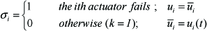
The Lock-In-Place (LIP) fault is one of the most common actuator faults, resulting in the non-responsiveness of the actuator. For this type of fault, we can transform system (7) into the following form:

where:

where ki is the loss coefficient of the fault and
3. Reconfiguration Control Law
A linear reference model is selected as follows:

where
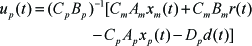
In order to reconfigure the failure system and compensate for the loss of control under actuator faults, the following reconfiguration control law is chosen:

where
When the actuator fails, the control input of the reconfiguration system can be described in the form:

Then, system (7) can be rewritten as:

Let e = xp – xm represent the state error vector, then we can obtain:

In order to guarantee the asymptotic convergence of the state error e(t), the following equations should be satisfied:


Substituting (15)–(17) into (14), then we can get:

where
To guarantee the asymptotic convergence of the state error e(t), that is:


Where

A positive definite Lyapunov function can be chosen in the form:

where

for any constant matrix
Next, we combine (20) with (22) and we can get the time-derivative of V described as:

which verifies that the closed-loop system can be kept in stability by applying the reconfiguration controller (11).
From (24), we can know that 0 ≤ V(t) ≤ V(0), and then V(t) ∈ L∞.
By integrating (24), we can obtain the equation:
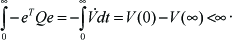
The global stability of the system can be attained by (25). Hence:

and
The block diagram of the entire control system is presented in Figure 2.

Optimal reconfiguration control scheme via adaptive control and combined multiple models
Reference Model Design via Optimal Control
A standard linear time-invariant flight control system can be constructed by the state-space equation:
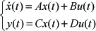
where x(t) is the state vector, u(t) is the control input vector and y(t) is the output vector. For system (7), the optimal performance index can be introduced as follows:

where Q(t) and R(t) are the weighted matrices of the state vector and input vector. They satisfy:

The object of the optimal control is to calculate the control u(t), which guarantees that the index J(x, u) will have a minimum value. Thus, a Hamilton function [27] can be selected as:

Using the principle of minimum cost, the optimal control law can be obtained as:

where K is the linear optimal control matrix and P is the unique symmetrical positive solution to the Riccati equation, shown as follows:

Considering that Equation (31) satisfies Equation (32), then the state control matrix after optimization can be attained as follows via eigenvector values:

5. Combined Multiple Models Scheme
In particular flight operating conditions, actuator failures can cause the system parameters to change abruptly from one region to another and thus the time interval needed for a single adaptive controller to compensate the failures may be large. Over this interval, the performance of the system can deteriorate substantially and may be unacceptable in practice. Hence, a single model-based adaptive control method cannot achieve the control object. Because of this, the multiple model control approach is applied.
In this paper, the combined models set includes several fixed models, an adaptive model and a reinitialized adaptive model. The fixed models whose parameter vectors will not vary relative to the surroundings can draw near the failure system according to different faults, while the adaptive model is utilized to ensure the convergence of the identification error. The reinitialized adaptive model can be replaced with a fixed model which is closest to the current actual model of the system at every time interval.
5.1 Fixed Models and Controller Design
In this part, two fixed models corresponding to two classes of fault are designed as the following forms:

To get parameterized model forms, we can define the variables


According to the reference model, the tracking object is:

Then:
As such, the controllers for (36) and (37) are:


5.2 Adaptive Model Design
Suppose that there are n actuators which fail, that is:

Then, system (7) will be described as:

where bi is the ith column of Bp.
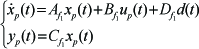
Thus, a series of identification models are constructed as:

where ûki is the estimate of ūki.
By (43) and (44), the estimation error (

where

where

where
5.3 The Reinitialized Adaptive Model Design
When there are errors between the controlled system and the fixed models, the reinitialized adaptive model can update the parameters automatically with the object of tracking the failure system. Thus, the initial value of the adaptive model can be reset to the closest fixed model. The adaptive model can be described as the following state equation:

where
We define

where η(t) is a positive real number and η(t) ∈ (0, 2).
6. Simulations
6.1 Helicopter Model Parameterization
According to the descriptions in Section 2, general models of attitude and position can be constructed for the helicopter. We choose the angle state vector


where:

The main parameters associated with the quadrotor model are given by the following table [26].
Values of the model parameters

6.2 Numerical Experiment
In this paper, the situation in which one propeller is locked and loses its control effectiveness is considered for the faulty helicopter. Thus, the construction of multiple models can be formulated in terms of certain patterns:
No fault;
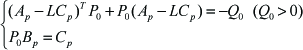
With appropriate switching under different fault patterns, the proposed control scheme exhibits superior performance compared to the normal multiple models based adaptive control method. Under pattern 5), Figure 3, Figure 4 and Figure 5 show the curves of the tracking errors in terms of pitch angle, yaw angle and height using the proposed scheme and the normal multi-model adaptive control method. The curves of the tracking errors with external disturbance, where:
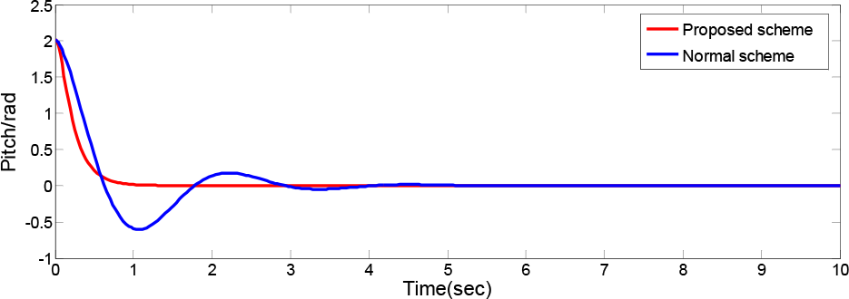
Tracking errors of the pitch angle using the proposed and normal schemes

Tracking errors of the yaw angle using the proposed and normal schemes

Tracking errors of the height using the proposed and normal schemes

are illustrated in Figure 6, Figure 7 and Figure 8 for comparison.

Tracking errors of the pitch angle using the proposed and normal schemes with disturbance

Tracking errors of the yaw angle using the proposed and normal schemes with disturbance

Tracking errors of the height using the proposed and normal schemes with disturbance
From the curves in the first three figures, we can see that a weaker oscillation (having almost no oscillation in Figure 3 and Figure 4) and a faster convergence (within 1 s to 2 s) of the tracking errors are attained under the proposed control scheme. In the last three simulation figures, where the disturbance occurs at 5 s, we can see that a higher speed of asymptotic convergence and better response lines (the oscillation under disturbance is very weak after 5 s) are achieved by applying the proposed reconfiguration control method. The tracking errors tend to zero and the overall system stability is also guaranteed. Meanwhile, the control capability of the normal scheme seems to be less effective. The method is also tested on a real-time simulation platform (Qball-X4, of Quanser Company - see Figure 9) online [26], and the results are provided in Figure 10 and Figure 11.

Quanser Qball-X4

Tracking error of the pitch angle in online simulation

Tracking error of the yaw angle in online simulation
Compared with the numerical simulations of the pitch and yaw angles (see Figure 3 and Figure 4), the real-time experiments (see Figure 10 and Figure 11) can also ensure the approximate stability of the system under the reconfiguration control scheme, which demonstrates its excellent ability in practical applications. Some fluctuations (generally within the region from −1 to 1) in the figures are the results of the nonlinear characteristics of the online Qball-X4 system. However, the values of these fluctuations are low, so the system can still run well and achieve good tracking. The aircraft shown in Figure 9 has superior performance in position tracking simultaneously.
7. Conclusions
This paper has derived a new reconfiguration control scheme for a quadrotor helicopter with actuator faults. The method synthetically applies direct adaptive control and the combined multiple models. An optimal control design has been considered for the construction of the reference model. With appropriate switching of the multiple models, the asymptotic tracking of the states is ensured and the speed of convergence is improved by adding the reinitialized adaptive model. The reconfiguration ability is confirmed through the simulation results. This work provides an improvement on existing results in the reconfiguration control literature. Future work will focus on the fault estimation and fault tolerance of a quadrotor with nonlinear terms.
Footnotes
8. Acknowledgments
The project was supported by the National Natural Science Foundation of China (61374130), a project funded by the Priority Academic Programme Development of Jiangsu Higher Education Institutions.