
Abstract
This paper presents a 2D indoor localization and orientation system based on a TDOA (Time Difference of Arrival) technique. It uses an array of receivers (four low-cost ultrasonic resonant devices in a square distribution) to implement low-computational-effort DOA (Direction of Arrival) algorithms, based on assumed plane-wave reception. The system only demands two transmitters at well-known positions on the ceiling of the room for obtaining the node position and orientation when it is deployed on the floor of the room. This system has been tested using a Xilinx Spartan-3A FPGA that implements a 52 MHz MicroBlaze. The experimental results include a total of 1,440 points, obtaining a mean localization error of 5.17 cm and a mean orientation error of 3.34°. For this system, the localization and orientation processes are executed in less than 50 us.
1. Introduction
Low-cost and precise indoor localization systems are currently in high demand for new commercial robots. From robots that clean floors to robots that emulate the behaviour of a waiter, knowledge on the position and orientation of the node is one of the most important requirements to implement accurate navigation systems.
Nowadays, a robot can find out about its indoor localization with various technologies. From systems based on radiofrequency [1] to systems based on image processing [2, 3, 4], there are multiple systems that allow it to ascertain the position of an object. The decision depends on multiple factors, such as the resolution demanded by the application or the cost. Among all localization systems, the one that allows a relatively high precision with an associated low cost is the one based on ultrasound technology [5].
Ultrasonic systems can be divided into two main groups in terms of the propagation delay measurement. TOA (Time of Arrival) systems [6, 7, 8] estimate the absolute distance between the node and the reference points, while TDOA (Time Difference of Arrival) systems use the difference of the propagation delay of a reference wave between multiple points.
Traditional TDOA systems use the intersections of hyperboloids to obtain the position of the node [9–14]. The main disadvantage of these systems is the high computational cost, so they usually implement minimization algorithms. There are also TDOA systems that are based on estimating the direction of arrival (DOA) of the reference wave [15–18]. As with hyperboloid TDOA systems, these systems present a high computational cost as they need trigonometric and/or minimization functions.
In this paper, an evolution of a previous TDOA system (ALO − Angle Localization and Orientation [19]) is proposed. The ALO system (ALO3 from now on) is characterized by its low computational cost, allowing the implementation of localization algorithms without minimization or trigonometric functions.
The evolution with respect to ALO3 consists in adding one additional receiver to the node, moving the reference point of the node to a point in the middle of the receivers. This almost removes the error in considering the arrival of the ultrasonic signal as a plane wave, significantly improving the system performance without increasing the computational effort. This new proposed system will be referenced as ALO4 from now on.
The rest of the paper is organized in eight main sections: “ALO4 System”, describing the new TDOA system; “Computational Effort”, analysing the cycles needed by an embedded microprocessor to execute the localization and orientation processes; “ALO4 Error Analysis”, where plane-wave approximation error is analysed using the new distribution; “Calibration”, which describes the process followed to improve the estimation of the direction of arrival; “Implementation”, where the description of the implemented system can be found; “Deployment” where a description of how to deploy transmitters is shown; “Mobility Performance”, where an analysis of the performance of the localization and orientation system is made when the node is moving; and “Results”, where the experimental results are presented.
2. ALO4 System
The ALO4 system is based on the same principle as ALO3: estimating the direction of arrival of the reference wave, measuring the propagation delay between receivers. The only difference is that the node reference point is between its four receivers (Figure 1).

ALO3 − ALO4 reference points
This new approximation allows the capturing of more precise measurements of the propagation delay between receivers. When choosing one receiver as the reference point, as the signal does not arrive as a plane wave to the node, the distance measured (dm) will always be smaller than the ideal one (d).
When the reference point is the midpoint between receivers, the reference signal will also arrive earlier at the nearest receiver, but later at the second one, so the measured distance will be more similar to the ideal one. This effect can be clearly observed when only two receivers are involved (Figure 2), but the same effect exists between the configurations of ALO4 and ALO3.

Comparison of measured (dm) and ideal (d) distances in ALO3 and ALO4
Mathematically, ALO4 angle estimation (Figure 3) formulae are ‘identical’ to those of ALO3. As the reference point is in the middle of the receivers, the distance measured must be divided by two, but as the distance from the reference point to the receiver has also been divided by two the equations do not change.
ALO4 angles obtained with Equation (1)

d1 = distance measured between R1 and R2
d2 = distance measured between R3 and R4
a = distance between receivers
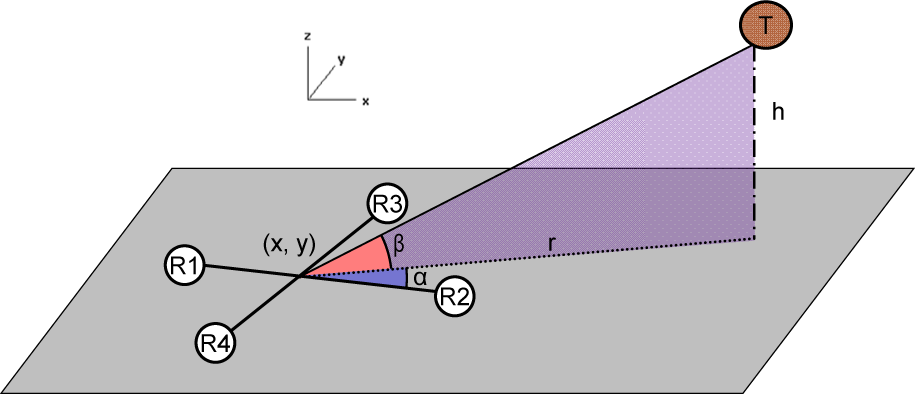
With these angles, localization (Equation 2) and orientation equations (Figure 4) are identical for both systems.

ALO angles and vectors required for the orientation process

rx = distance from the projection of transmitter X on the floor to the node
h = height of the ceiling
b = distance between transmitters
βx= vertical angle measured to transmitter X
(Px, Py) = vector from node position to the transmitter projection over the floor.
(Nx, Ny) = vector that represents the system North.
3. Computational Effort
Computational cost associated to this system can be measured in the number of clock cycles needed by the microprocessor to execute the algorithm. In this case, the chosen microprocessor is MicroBlaze [20], which is an embedded microprocessor used in FPGAs.
The first consideration is that the use of ultrasonic signals considerably reduces the noise that is captured by the receivers, so the node does not need to implement any kind of filters or process the incoming signal [21] to deduce that a transmitter is emitting. The transmitter ID is deduced from the time between transmissions (see section 7 for more details), so this does not represent a computational cost either. The main computational cost is represented by the localization and orientation algorithms.
Analysing the equations described in the previous section, the minimum requirements demanded by the system are as follows:
Localization needs 10 multiplications (h2, a2, b2 and 2b are constants), nine add-subtract operations, three divisions and one square-root, representing a total of 10.4+9.4+3.28+1.27=187 clock cycles.
Orientation, considering that system North is (0, 1), two multiplications, two adding operations, one division and one square root, representing a total of 71 clock cycles.
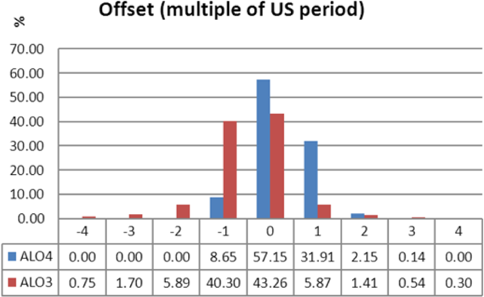
Due to the use of resonant receivers, we have observed that measures can contain an error that is a multiple of the reference signal period (see section 9, Figure 12, for more details about this error), which is treated as a variable offset. This offset generates a big error in the localization system, so in order to improve the localization performance the system iterates the localization process, adding or subtracting one ultrasonic period to the measure until the node position is near to the previous one. This error is never over +/− four periods (Figure 13), so, for the worst case, the system would need to perform nine localization iterations to correct the offset (if the offset is greater, the measures will be discarded).
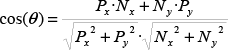
ALO4 localization error caused by plane-wave approximation

ALO4 orientation error caused by plane-wave approximation

General layout of the transmitters used in the experimental results

Node implementation
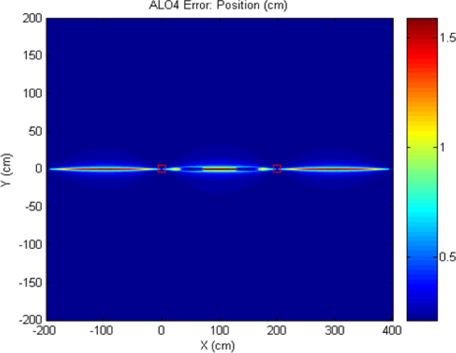
General-purpose board used for digitalization of the received signals

Transmitter deployment and coverage area: red for transmitter T5 and blue for T6)

Transmitter deployment (with extended coverage area: red for transmitter T5 and blue for T6)

Ultrasonic resonant devices offset error
Ultrasonic signal period offset applied to the captured measures
At the end, we must add some extra computational cost representing the control process of the algorithm (20% of the calculated computational cost), obtaining a total of 2105 clock cycles. In our implementation, we use a Xilinx Spartan-3A FPGA that implements a MicroBlaze working at 52 MHz, so the localization and orientation processes only need 40.5 us (less than two ultrasonic periods) to be executed.
This computational cost is negligible in comparison to other DOA [17] or DTOA [22] systems, where minimization functions are used, allowing low-cost implementations.
4. ALO4 Error Analysis
The only error source, of the ones detailed in [19], that is affected by the new receiver deployment is the plane-wave approximation error. This error occurs because, as the distance between transmitter and receiver is not infinite, the reference signal does not arrive at the node as a perfect plane wave. As the system considers the plane-wave arrival in order to simplify the localization and orientation algorithms, this simplification introduces an error in the final performance.
In this section, the effects of this error on the localization and orientation system are analysed and compared to the one obtained for ALO3.
4.1 Localization Errors
To measure the effect on the localization process of the plane-wave approximation error, a simulation was executed using an environment with two transmitters at positions (0, 0, 280) and (200, 0, 280) cm, and a node whose distance between receivers is 10 cm. The node is deployed at different positions (x, y, 0) and is always orientated to the system North. The error between the position of the node and that obtained after the localization process is shown in Figure 5.
Note: In the simulation figures, the red squares represent the projection of the transmitters over the floor.
The mean error obtained for this simulation is 0.05 cm, 100 times lower than the error reported by the same simulation for ALO3.
4.2 Orientation Errors
The plane-wave approximation also introduces errors in the orientation due to the fact that the measured and ideal distances (dm and d in Figure 2) are not the same. This has an impact on the horizontal angle (α in equation 1), and therefore also the orientation. To measure its effect, a simulation of a node with its receivers deployed at 10 cm was carried out (Figure 6).
In this simulation, the node estimates the horizontal angle (α in equation 1) in relation to only one transmitter at (0, 0, 280). When more than one transmitter is available, there is redundant information, which can be used for minimizing the error. However, in this simulation only one transmitter is used in order to highlight the effect of the plane-wave approximation.
The mean error obtained for this simulation is 5·10−40, 10,000 times lower than that obtained for ALO3.
5. Calibration
To obtain more accurate results in the ALO3 and ALO4 localization and orientation processes, a calibration procedure was defined. The objective of this calibration process is to reduce the errors generated by an incorrect estimation of some parameters of the system (ceiling height, distance between receivers and transmitters or the sound propagation speed) and to compensate the error of the different propagation delays between the analogue conditioning circuits used for each receiver.
The calibration process includes the following steps:
Deploy the node at an arbitrary point on the map.
Capture the ALO3 and ALO4 differential times of arrival with respect to the system transmitters and with four different orientations (02, 902, 1802 and 2702).
Remove the offset generated by ultrasonic resonant devices. This error is detailed in section 8 and Figure 12. As all the captured measures are referenced to the same position, the localization results after removing this error offset shall be referenced to a small area.
When all localization points share the same area, modify the initial system parameters trying to minimize this area where the measures are represented (adjusting the ceiling height, sound propagation speed and the distance between receivers/transmitters).
To conclude, apply a fixed time to the measured propagation delay between the node receivers, trying to minimize the area where the measures are represented. The objective of this offset is to consider the error caused by the different propagation delays in the analogue conditioning circuit for different receivers.
6. Implementation
The ALO4 system was deployed using four transmitters on the ceiling of a room and a node on the floor area between transmitters (Figure 7).
The prototype developed is shown in Figure 8. It consists of three main layers: receiver board, analogue conditioning board, and FPGA board.
The receiver layer consists of four ultrasonic receivers, model 400SR120, deployed in a square distribution with a diagonal of 10 cm.
For the analogue conditioning board we use a general-purpose board not specifically designed for this experiment (Figure 9). This board provides multiple functionalities (ADCs, motor drivers, Zigbee, etc.). The system only requires the board in the digitalization phase, which consists in:
A first RC filter: To remove the DC component of the received signal.
An amplification stage: As the signal received is weak, it is amplified with an INA2331 amplifier.
A second RC filter: Due to the high gain of the amplification stage, a continuous component appears at the output of the previous stage. This filter removes this component for each channel, setting the amplified signal mean value to 0 V.
A diode attached to GND: To prevent the sending of negative voltage signals to the input of the comparator stage, this diode removes all the negative part of the amplified signal.
A comparator: To digitalize the signal, a comparator is used. This comparator (model TLC352CP) is included in a small separate board (see Figure 8). The output of this stage is the input of the FPGA board.
The FPGA board is a Spartan-3 Evaluation Board from Digilent. The FPGA implements a MicroBlaze embedded microprocessor with a custom PLB peripheral. In this peripheral, the difference time of arrival is obtained. The MicroBlaze microprocessor accesses this peripheral to obtain this information and calculates the node position and orientation applying equations (1), (2) and (3).
The transmitter system is controlled by another Spartan-3 Evaluation Board. The FPGA generates trains of 15 pulses (with a frequency of 40 kHz) for each transmitter with the timing modulation detailed in section 7. Before the signal arrives at the transmitters (model 400ST120), the signal voltage level is converted from the range provided by the FPGA (0 − 3.3 V) to a more effective range for the transmitters (0 − 20 V) with push-pull driver L293B.
7. Deployment
In order to adequately cover the localization area, the transmitters must be deployed according to the following principles:
Transmitters are grouped in nine groups (ID numbered from 1 to 9) and are deployed following the structure shown in Figure 10.
Distance between transmitters is fixed and shall be calculated to guarantee that the signal generated by a transmitter can be correctly received on the floor point under any adjacent transmitter. This distance depends on the transmitter potency, the receiver sensitivity, the precision of the analogue conditioning circuit in the node and the height of the ceiling.
Transmitters of the same group transmit the signal at the same time, but the distance between them is great enough that any receiver will only receive the signal from one transmitter of each group at a time.
The time elapsed between transmission is defined as 55 ms + 2·ID ms. This gap guarantees that the time between any pair of transmitters of different groups is unique, and the node can identify the transmission group measuring the gap between received signals.
The node uses its previous position to discriminate between transmitters of the same group. Therefore, an initial position must be given, although it can be an approximate one, as it is only used to distinguish between very distant receivers (those of the same group which share ID).
This deployment guarantees that any given area is covered by at least two transmitters, and all transmitters emit each second, so the node can update its position and orientation at this rate, without any initialization process. The only initialization requirement is that the initial position region must be known.
This deployment is valid for areas without obstacles. As ALO4 requires line of sight between the node and the transmitters, if the area contains multiple obstacles, the system will report big localization errors for the zones with bad coverage. To minimize this effect, transmitters shall be deployed closer, covering the area with obstacles with multiple transmitters from different angles.
For example, deploying the transmitters close enough together, as shown in Figure 11, enables some areas to be covered by more than 14 different pairs of transmitters, increasing the possibility that there is a line of sight between the node and any given pair of transmitters.
The time modulation method requires all transmitters to be synchronized. In our implementation, this synchronization was provided by a unique FPGA board controlling all transmitters of the system.
As can be seen, the main drawbacks of the proposed system are that it needs direct line of sight and also multiple transmitters on the ceiling. When direct line of sight is not possible in all zones, a multiple localization system should be used, adding some other method (i.e., wheel encoder). The advantage of the proposed method is that its error is non-cumulative (the error of each measure does not depend on the error of previous measures, as in wheel encoders, for instance) and it uses low-cost resources. Both transmitters and receivers are low-cost devices, and processing requirements are small, so they can be implemented with low-cost microcontrollers.
8. Mobility Performance
In order to obtain a low-cost implementation, ultrasonic resonant devices and simple conditioning circuits are proposed for both the transmitter and receiver. However, in this case different transmitters cannot emit simultaneously. If the node is moving, this will have an important impact on the localization, as the node position changes between receiving different transmitter signals. This error is affected by:
Node movement direction.
Position of the node.
Time elapsed between transmitter emissions.
Node speed.
Simulations with changes in all these parameters were carried out using the deployment setting of section 6. The node was deployed at all points in a grid of 1 cm in the area covered by the transmitters. The results are summarized in Table 1.
ALO4 localization and orientation errors occurring because all transmitters do not emit simultaneously and the node is moving
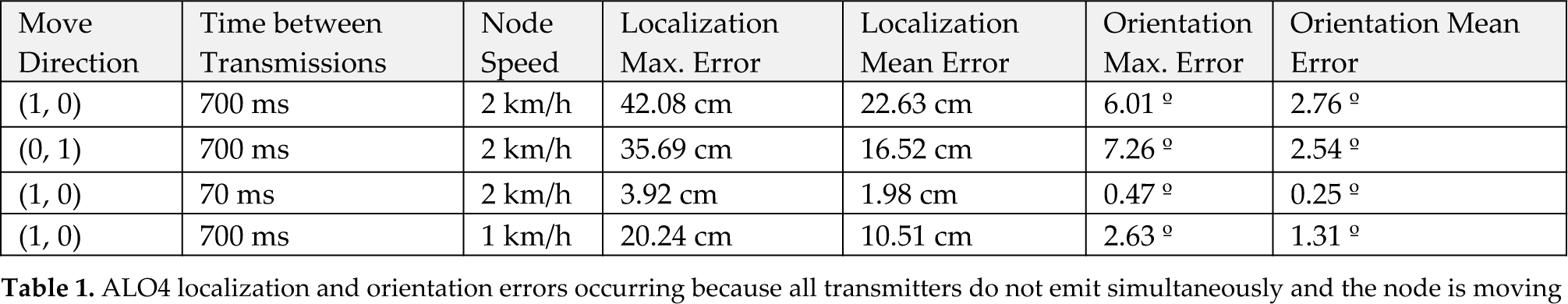
As can be seen, node speed and time between transmissions are the most critical aspects, as they both change the position of the node when different transmitters are received. An important conclusion is that non-simultaneous transmitters are not suitable for localization while the node is moving. If localization when the node is stopped is not enough, then simultaneous transmitters should be used.
In order to achieve simultaneous emission of all transmitters, modulating the ultrasonic signal is necessary. However, this increases the complexity and cost associated to transmitters and receivers (low-cost resonant devices cannot be used) and conditioning circuits.
Even when all transmitters emit simultaneously, there is also an error when the node is moving, as the different receivers are not in the same position. This is affected by:
Distance between receivers.
Position of the node.
Node movement direction.
Node speed.
The errors in the vertical angle estimation will generate an error in the localization, while errors in the horizontal angle will affect the orientation. Simulating the effect of these errors on the environment defined in section 6, we obtain the results summarized in Table 2.
ALO4 localization and orientation errors caused by node movement using simultaneous transmitters

These errors are inherent to the ALO4 system when the node is moving, so they cannot be easily removed. Table 2 shows that the node speed is the most important parameter to be taken into account in this case, with almost linear behaviour. However, the localization error is acceptable for typical indoor-robot speeds.
After these simulations, we can conclude that the ALO4 system is suitable for mobile nodes only if transmitters emit at the same time.
9. Results
To measure the precision of the ALO4 system, a comparison with the ALO3 system was carried out. The node in Figure 8 was placed at different points in the environment defined in section 6. A total of nine points were analysed, and at each point 10 different measures were taken for four node orientations (0°, 90°, 180° and 270°) and for each transmitter, generating a total of 360 localization measures.
As we have four transmitters in the defined environment, and the system can calculate its position with respect to only two of them, the system applies the localization algorithm with respect to each pair of transmitters forming one side of the square where they are deployed. This implies that four different positions are calculated for each measure (obtaining a total of 1,440 localization points).
The ALO3 system only needs three receivers to perform the localization process, but the node has four receivers, so for each measure the localization process is applied four times (switching the reference point at the receiver), obtaining a total of 5,760 localization points.
As our implementation uses resonant devices, an offset error (Δ′ in Figure 12) is sometimes added to the ideal time (Δ) between the captured signals. This error is caused because the reference signal does not arrive with the same strength and angle at all receivers, so the comparator will not always detect the signal after the same number of cycles. This error is always a multiple of the ultrasonic wave period (Δ=Δ′ ± n·T), and causes substantial error in the localization results (i.e., an error of one ultrasonic period at any measure causes a localization error of up to 55.6 cm). However, the error can be easily removed by a simple algorithm: the node only needs to add or subtract the ultrasonic period to the captured measures until the resultant position is near to the previous one.
The offset error detected and corrected on the captured measures (measured as an integer number ‘n’ of ultrasonic period ‘T’) is detailed in Figure 13.
After correcting this error, the node position results of the localization process are summarized in Figure 14 (ALO3 system) and Figure 15 (ALO4 system).

ALO3 localization results

ALO4 localization results
As can be seen, the ALO4 system has higher positioning accuracy and lower positioning jitter. To measure these effects, the absolute error between the ideal point (where the node was deployed) and the point reported by the localization process was calculated for both systems, and these results are shown in Figure 16.
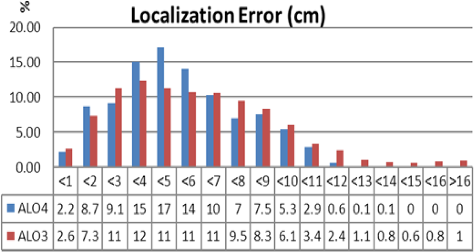
Localization error for ALO3 and ALO4
ALO3 obtained a maximum positioning error of 20.89 cm (with a mean error of 5.89 cm and a standard deviation of 3.30 cm) while the ALO4 maximum error was 13.03 cm (the mean error was 5.17 cm and the standard deviation 2.51 cm). The mean error corresponds to the positioning accuracy, and the standard deviation to the positioning jitter.
Comparing the ALO3 localization results with the results obtained by ALO3 when no calibration was carried out [19], it can be concluded that the calibration process is very important for these systems as it reduces the localization error by more than 33%.
Important comparisons can also be made with other, similar localization systems. The precision results are very similar or even better than those of other TDOA systems (about 10 cm in [23]), but using much simpler localization algorithms. On the other hand, TOA systems can obtain some further accuracy (3 cm in [24]), but they need an auxiliary synchronization system (usually RF) between node and transmitters, which is avoided in TDOA implementations such as ALO4.
Both the ALO3 and the ALO4 system report node orientation in relation to the system North. The errors in the reported absolute orientation, in degrees, are shown in Figure 17.

Orientation error for ALO3 and ALO4
The ALO3 system obtains a mean orientation error of 3.34° (its maximum error is 16.27° and its standard deviation 3.01°) while ALO4 obtains a mean error of 1.53° (with a maximum of 5.88° and a standard deviation of 1.09°).
10. Conclusions
This paper presents an inexpensive localization and orientation system for indoor environments based on ultrasound transceivers. It uses a TDOA technique, but with very simple algorithms, suitable for embedded systems. It is based on estimating the reception angle of an ultrasonic signal, calculated measuring the difference in the time of arrival between four receivers.
This system is an evolution of a previous system (ALO3), which used three receivers instead of four. With this new receiver, the localization and orientation performance is increased but keeps the localization and orientation algorithm as simple as its predecessor.
Analytically, the ALO4 system can estimate more precisely the arrival angle because it reduces the error that comes from considering the received signal as a plane wave. The current implementation of ALO4 obtains high localization and orientation errors when the node is moving, but these errors can be reduced drastically when all transmitters emit at the same time, making the system suitable for mobile nodes.
The experimental results show that ALO4 reduces the mean and maximum localization error to 12.22% and 37.63%, respectively, and the mean and maximum orientation error to 54.19% and 63.86% compared to its predecessor, and its precision is comparable to other TDOA and DOA systems that implement more complex algorithms.
Footnotes
11. Acknowledgements
This work has been supported by the Spanish Ministerio de Ciencia e Innovacion under project TEC2009-09871