
Abstract
Current magnetic systems for microrobotic navigation consist of assemblies of electromagnets, which allow for the wireless accurate steering and propulsion of sub-millimetric bodies. However, large numbers of windings and/or high currents are needed in order to generate suitable magnetic fields and gradients. This means that magnetic navigation systems are typically cumbersome and require a lot of power, thus limiting their application fields. In this paper, we propose a novel propulsion method that is able to dramatically reduce the power demand of such systems. This propulsion method was conceived for navigation systems that achieve propulsion by pulling microrobots with magnetic gradients. We compare this power-efficient propulsion method with the traditional pulling propulsion, in the case of a microrobot swimming in a micro-structured confined liquid environment. Results show that both methods are equivalent in terms of accuracy and the velocity of the motion of the microrobots, while the new approach requires only one ninth of the power needed to generate the magnetic gradients. Substantial equivalence is demonstrated also in terms of the manoeuvrability of user-controlled microrobots along a complex path.
1. Introduction
The field of microrobotics has experienced tremendous advancements in recent years [1]. Due to recent advances in milli- and micro-scale science and technology, and due to increasing demand for new microsystems for applications in medicine, biotechnology and manufacturing, creating tiny mobile robots has become a critical issue [2–3]. These tiny robots should be able to access enclosed small spaces down to the milli-scale, such as inside the human body, and should be able to manipulate and interact with milli/micro-scale entities. The fundamental challenge when decreasing robots' sizes below a millimetre is providing them with power and actuation. Magnetic propulsion is the best-established method for providing power and actuation at the milli/micro-scale [2]. Up to now, most of the research on magnetic propulsion and control for microrobots has been mainly focused on steering and propulsion systems that are able to generate tailored magnetic fields by employing electromagnets (i.e., coils) [4, 5, 6, 7, 8].
Yesin et al. [4] proposed a simple way to steer a magnetic device, whereby a Helmholtz coil and a Maxwell coil that align along the same direction are employed. Electromagnets are also used to steer microrobots in vitroretinal surgery and for targeted drug delivery [5]. The proposed electromagnetic system, called OctoMag, consists of eight electromagnets capable of controlling magnetic devices in five degrees of freedom (DoF).
Recently, some commercial solutions have become available. For example, a five DoFs robotic system based on electromagnets has been proposed for the control and steering of magnetic devices in biomedical applications [9].
Electromagnets are advantageous as permanent magnets [10, 11] because they allow for the fine control of the generated fields, leading to an accurate navigation. However, electromagnets are generally cumbersome and require high driving currents to generate adequate magnetic fields and, especially, gradients. This also implies that the power consumption and the heat produced by a magnetic navigation system could be very high [6, 8, 12].
In this work, we modelled, implemented and tested a novel propulsion method for the magnetic navigation of microrobots. In particular, we developed and implemented a propulsion method that significantly reduces power consumption without hardware modifications or loss of navigation performance. This feature makes our solution for power reduction very flexible for different platforms.
In our method, we considered the so-called “pulling” propulsion method [13], which consists of pulling a magnetic microrobot with magnetic field gradients. This method has been employed by different research groups for the propulsion of magnetic microrobots intended for medical applications. In particular, in [6, 8] 3D navigation of intravascular microrobots was achieved by means of a 2D magnetic field generator based on a planar assembly of Helmholtz and Maxwell coils. However, one of the issues to be solved was related to high power requirements. We implemented a power-efficient method specifically for this kind of electromagnetic system and then we employed a 2D magnetic navigation system to experimentally evaluate its performances. The obtained results can be directly extended to magnetic navigation systems, such as those mentioned above, that are specifically conceived for the steering of medical microrobots.
The paper is organized as follows: Section 2 describes the fundamentals of the magnetic steering and propulsion of microrobots by means of electromagnets. Section 3 describes both the traditional and novel power-efficient propulsion strategies. Section 4 describes the set-up used for the experimental evaluation of the developed propulsion strategies and the obtained results. Finally, discussions and conclusions are reported in Section 5.
2. Pulling propulsion by means of electromagnets
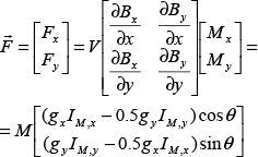
The magnetic navigation of microrobots consists of the generation of suitable forces F(N) and torques T (Nm) that can be expressed as [14]:


where B (T) is the magnetic field, V (m3) and M (A/m) are the volume and the magnetization of the robot, respectively.
These actions are usually produced by electromagnets in almost all the magnetic navigation systems that have been proposed until now in the literature [4, 5, 6, 7, 8]. In particular, most of them consist of different spatial arrangements of Helmholtz and Maxwell coil pairs [4, 6, 8]. A Helmholtz coils pair consists of two identical circular magnetic coils placed symmetrically one on each side of the experimental region along a common axis. The coils are separated by a distance d h equal to their radius r h . Each electromagnet carries the same electrical current flowing in the same direction. This particular configuration enables the generation of a highly-uniform magnetic field that can be used to apply a torque to a magnetic microrobot. In a Maxwell coils pair, instead, the electromagnets are separated by a distance d m = r m √3, where r m is the mean radius of the coils and the currents flow in opposite directions. The Maxwell configuration enables the generation of highly-uniform magnetic field gradients along its main axis. The generated gradients can be used to apply a magnetic force to the robot.
The magnetic flux density and its gradient, generated by the Helmholtz and Maxwell coils pairs along the main axis of the magnetic generators, can be reasonably considered to be constant. In particular, they can be related to the flowing current I by the following expressions:


where k and g are proportional coefficients that depend on the number of turns and on the radius of the Helmholtz and Maxwell coils, respectively [15]. Furthermore, in addition to the axial component of the gradient, the magnetic field generated by a Maxwell coil pair has a uniform gradient component in the radial direction. The amplitude of this radial component of the gradient is half that of the axial component.
3. Propulsion Strategies
We addressed two strategies for the magnetic navigation of microrobots. A traditional pulling approach, as already used in the literature [6, 8], was given as a reference. In parallel, we focused on the development of a different method aimed at reducing the power needed by the system without any performance loss. Then, the two propulsion strategies were compared in terms of performance, which is presented in the next section.
Both strategies implemented here are used in order to achieve the wireless 2D magnetic navigation of robots. Therefore, the system consists of an in-plane assembly of two Helmholtz coil pairs and two Maxwell coil pairs. One Helmholtz coil pair and one Maxwell coil pair are assembled along each of the two orthogonal directions x and y. However, the propulsion strategies can be extended for a 3D magnetic navigation, involving two different orthogonal arrangements of Helmholtz and Maxwell coils pairs that can be rotated in the space.
3.1. “Traditional” propulsion
Considering the architecture of a 2D magnetic navigation system and referring to the expression in (3), the in-plane magnetic flux density generated by the two Helmholtz pairs can be expressed as:

In particular, each Helmholtz coil pair needs to be mounted so as to generate a positive magnetic field when the current flows in the positive direction. Similarly, with regard to the Maxwell coils, each pair needs to be mounted so as to generate a positive axial gradient when the current flows in the positive direction. In this way, however, the radial component of the magnetic gradient of each pair is negative. Thus, the gradient in each direction results in the sum of the positive axial component of the pair along that direction and the negative radial component generated by the pair in the orthogonal direction. Considering the expression introduced in (4), the in-plane magnetic gradient generated by the Maxwell pairs can thus be described as [16]:

By means of the uniform magnetic field expressed in (5), the microrobots can be both magnetized (if they are paramagnetic) and aligned (if they are ferromagnetic) to an in-plane direction within the entire workspace. In fact, the alignment of the robot to the desired direction θ in the x-y plane was controlled by applying a magnetic field in that direction with the two orthogonal Helmholtz coils. From (2) and (5) we obtain:

Indeed, the orientation of the microrobots along the direction of the applied magnetic field occurs nearly instantaneously. Therefore, the dynamics of orientation is neglected and the robots are considered as always being aligned to the applied field. In particular, their magnetization can be expressed as:

where M is the remanent magnetization amplitude for ferromagnetic robots, or M=VχB where χ and B are the susceptibility of the robots and the amplitude of the magnetic field generated by the Helmholtz coils if the microrobots are paramagnetic.
The uniform magnetic gradient of (6) can instead be used to apply a propulsive force to the magnetized and oriented microrobots. According to (1), (6) and (8), this propulsive magnetic force can be expressed as:
Both in this traditional propulsion method and in the novel one described in the next section, the amplitude of the magnetic field was kept constant throughout the workspace and during the trials. This was done by fixing the module of the applied magnetic field. The orientation of the robots, instead, was controlled by varying the values of the field components according to (7).
According to the traditional propulsion method, the condition that the robot should move along the direction of orientation is imposed. Hence, the following condition is fulfilled:

By setting in turn
This thus results in:

In this way, a decoupled control of the orientation and speed of the motion of the microrobots is achieved. In fact, the direction of motion θ m is defined by the direction θ of the field generated by the Helmholtz pairs (Figure 1a). The magnitude of the propulsive force, instead, is directly controlled by the magnitude of the gradient generated by the Maxwell coil pairs. Moreover, the direction of orientation θ of the microrobots coincides with the direction of motion θ m .

Orientation versus direction of the motion of the microrobot in the “traditional” propulsion method (a) and in the power-efficient propulsion method (b).
3.2. Power-efficient propulsion
The generation of high magnetic fields and large gradients needed for the effective propulsion of microrobots requires high currents and/or large number of windings in the coils. Consequently, magnetic navigation systems need cumbersome hardware, which poses limits to the maximum achievable workspace size. Moreover, this also means that power consumption as well as the heat dissipated by the magnetic navigation systems can be very high [6, 8]. The related risks are the overheating and consequent damage of both the coils and the substrate/robot (which, in some biomedical applications, could compromise the results). Therefore, we developed a novel propulsion method that significantly reduces the power consumption compared to the previous method. This power saving can be achieved without hardware modifications or losses in navigation performance.
The novel propulsion method involves the reduction of the amplitude of the currents flowing in the Maxwell coils. These coils are continuously used during the operation and their resistances are typically higher than those of the corresponding Helmholtz coils. Thus, a decrease in the currents flowing in the Maxwell coils has a dramatic impact on the power consumption of the overall platform.
Considering (6), the amplitude of x (y) component of the magnetic field gradient is half that generated by the x (y) Maxwell coils pair. This is due to the overlap of the radial component generated by the y (x) Maxwell coils pair. Hence, in the traditional control method, half of the magnetic gradient generated by each Maxwell pair is sacrificed, with the only advantage being that the microrobot is aligned along the direction of the magnetic field movement (i.e. θ = θm).
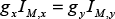
If the geometrical and magnetic anisotropy of the propelled microrobots is not particularly high or the orientation control is not crucial for the specific task, such as for motion tasks, there is actually no special need to align the microrobot to the direction of the motion, as it is instead prescribed in the traditional propulsion method. Hence, it is possible to increase the effective magnetic gradient with respect to the flowing currents by removing this constraint. This is the approach proposed in this paper for a power-efficient propulsion method. Changing the direction of I M,x or of I My in (6), such as IM, x= -IM,y = IM, each component of the resulting magnetic gradient becomes 1.5 times that of the gradient generated by each Maxwell pair. This comes about thanks to the overlap of the radial component of the gradient generated by each Maxwell pair, as follows:
Considering (13), the direction of motion θ m no longer coincides with the direction of orientation θ of the field. In particular, it is found that the orientation needed in order to move along the direction θ m is θ = – θ m (Figure 1b).
As a consequence, the same gradient and the same propulsive force can be generated with currents that are one third of those needed in the traditional propulsion method. The result is that, by implementing this propulsion method, the overall power consumption of the platform can be significantly reduced.
For example, to demonstrate this aspect, Figure 2 shows the simulated power consumption of the magnetic navigation system used in the experimental evaluation (Section 4) when setting the typical magnetic values used during the experiments.

Power consumed by the magnetic navigation system used in the experimental evaluation by using B = 4 mT and ∇B = 0.6 T/m. Graphs show the simulated power consumption versus the direction of the motion when applying the (top) traditional and (bottom) power-efficient propulsion strategies. In the conditions considered, the power-efficient propulsion method enables a reduction of about 85% of the power consumption of the system.
4. Experimental Evaluation
An experimental comparison of the performance of the microrobotic system implementing the above propulsion strategies was performed to demonstrate the equivalence of both approaches. In particular, we compared the traditional and the power-efficient propulsion strategies in terms of accuracy of movement direction, response time of the actuation of the microrobot, propulsion velocity, and manoeuvrability. For the latter test phase, we adopted the requirements of the “Mobility Task” of 2011 NIST Mobile Microrobotics Challenge as the experimental protocol, as it is described in section 4.2 and in [15, 17].
4.1. Magnetic navigation setup
The magnetic microrobotic system consisted of a magnetic field generator, an electronic and imaging system, and microrobots swimming in a water-filled miniature arena (Figure 3) [15].

The magnetic microrobotic system. The microrobot (with a diameter of around 500 µm) swims in an arena (3.5 mm × 2 mm) positioned at the centre of the magnetic coil system. Top right picture, courtesy of Massimo Brega.
The microrobots used consist of near-spherical magnetic bodies designed to operate in aqueous liquid environments. They were fabricated according to the procedure described in [18, 19], and have a typical size of a few hundred microns.
The microrobots embed dispersed superparamagnetic nanoparticles, which endow them with a typical paramagnetic behaviour (no hysteresis, susceptibility χ of about 2⋅10−2 and saturation magnetization M s of about 1.4 kA/m) [18, 19]. We observed experimentally that the minimum level of anisotropy in the shape and in the distribution of the magnetic material within the microrobots body due to the fabrication process is sufficient to allow them to be oriented by the applied magnetic field. Considering the properties of the microrobots, we evaluated that a magnetic flux density and a gradient of 10 mT and 1 T/m, respectively, provide proper navigation performances. The coils of the magnetic field generator were designed to achieve these target values of magnetic field and gradient with maximum currents of about 2 A. According to these design specifications and by reducing the encumbrance of the magnetic system, the features of the coils are summarized in Table 1.
Properties of the coils composing the magnetic navigation system. The diameter of the copper wire for all the coils is 0.28 mm

Finally, the microrobotic platform also comprises a PC, a joypad (SAITEK P580 Blue Rumble Pad), two cameras (BASLER scA1390-17gc and Genie HM1400, alternatively used), a data acquisition board (NI DAQ USB-6259), custom driving electronics and a liquid microenvironment (water volume of about 7 µL), termed arena [15]. Moreover, the system is managed using a control software, which includes a graphic user interface (GUI) developed with LabVIEW© (National Instruments, Inc., USA).
4.2. Experimental results
The movement direction, response time, velocity and manoeuvrability of the microrobots, when employing both the traditional and the power-efficient propulsion strategies, were evaluated experimentally.
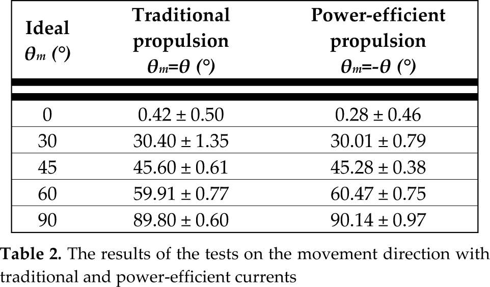
A first set of tests was carried out to evaluate the ability of the microrobotic system to steer the body along a prescribed direction of motion. In all the experiments, the microrobot was first aligned to the orientation required by the specific propulsion method in use in order to move along the desired direction (i.e., the currents are only in the Helmholtz coils). Orientation was obtained by means of a magnetic field with an amplitude of 8 mT, produced by the Helmholtz coils. Then, an effective magnetic gradient of 0.5 T/m was applied by means of the Maxwell coils in order to achieve motion along the prescribed direction. All the experiments were performed with the same robot. For each direction of motion, eight tests were carried out for both propulsion strategies. The results, reported in Table 2, demonstrate the equivalence between the propulsion strategies in terms of accuracy and the repeatability of the motion of the microrobot (confirmed by a t test with a p value of 0.01). Moreover, they demonstrate that the actual direction coincides with the desired one (angular coefficient of linear interpolant is 1), leading to good motion accuracy and repeatability.
The results of the tests on the movement direction with traditional and power-efficient currents
A second set of experiments was carried out to compare the response time of microrobots with our navigation system by employing the two propulsion strategies. In particular, we evaluated the time delay between the input by the control software and the motion of the microrobots. The Genie HM1400 camera was used in these experiments because a higher frame rate was needed in order to reduce measurement errors (images are acquired at 400 fps). The experimental protocol involved the continuous acquisition of images for five seconds. After one second from the start of each test, a magnetic field of 8 mT and a magnetic gradient of 0.2 T/m were contemporarily applied for one second, thus propelling the microrobot. In different experiments, the microrobot was propelled along 0° and 90° to evaluate the time delay produced by the coils used for both x and y directions. The results of all the tests with both propulsion strategies showed that, at the beginning of the movement, the microrobot was oriented and went forward with a delay of 17.5 ± 2.6 ms, whereas at the end of the movement, the microrobot stopped 18.0 ± 4.4 ms after the currents were switched off. The obtained standard deviations are of the same order of magnitude of the time step of the image acquisition.
Considering that microrobots are typically propelled at a few bodylengths per second, the intrinsic delay introduced by the magnetic actuation is much smaller than the typical movement dynamics. For this reason, this delay can be neglected and the microrobots can be considered as instantaneously responding.
The following experiments focused on identifying the velocity that a microrobot can achieve with both propulsion strategies. The objective of this evaluation of the propulsion velocity was to compare and verify that similar performances can be achieved by using the power-efficient control method with respect to the traditional one, when the magnetic field magnitude and gradient are fixed. However, the achievable speed is strictly dependent on the properties of the propelled microrobot, as well. For this reason, the same microrobot was employed for all these experiments. The mean velocity was evaluated by applying a magnetic field of 8 mT and a magnetic field gradient of 0.15 T/m. The microrobot was propelled along directions x and y by using both control strategies. For each direction, five tests were performed.
The results, reported in Figure 4, demonstrate that the two control strategies are substantially equivalent in terms of the propulsion speed achieved, although the currents that flowed in the Maxwell coils were 0.45 A for the traditional propulsion and 0.15 A for the power-efficient propulsion. The smaller velocity for the power-efficient control method could be due to bigger fluid dynamic frictional forces because, in this case, the orientation of the robot is not along the direction of motion.

The velocities obtained with the traditional control method and the power-efficient control method when the robot was steered along the × (1.65 ± 0.02 mm/s and 1.59 ± 0.07 mm/s respectively for the traditional and the power efficient control method) and y directions (1.42 ± 0.13 mm/s and 1.33 ± 0.19 mm/s respectively for the traditional and the power efficient control method).
Finally, we investigated the manoeuvrability of the microrobot when the system was controlled by a user. The experimental protocol involved steering the microrobot along an eight-shaped path in the arena as shown in Figure 5.

Schematic representation of the performed eight-shaped path in the arena. Numbers indicate the sequential position of the microrobot during movement.
The maximum deflection of the knob (Figure 3) corresponded to an effective value of the magnetic field gradient of 0.15 T/m while the magnetic field was kept at 8 mT, defined by the software interface. These values were chosen because they represent the best trade-off between high speed and good controllability with the selected microrobot. The test was performed by three different users, five times each. Table 3 shows their time scores (tMT) obtained with both the traditional propulsion and power-efficient propulsion. It should be noted that, from the user's point of view, there is no difference between the two propulsion strategies. In both cases the user controls only the direction and the speed of motion, while the control software calculates the driving currents (0.45 A and 0.15 A in the Maxwell coils for the traditional and the power-efficient propulsion method, respectively) required to steer and propel the microrobot.
Results of manoeuvrability tests using traditional and power-efficient propulsion strategies

These results confirm that traditional and power-efficient approaches provide equivalent performances in terms of manoeuvrability. Moreover, the users did not perceive any difference between the two propulsion strategies.
5. Discussions and Conclusion
Milli/microrobotics technologies require high accuracy, repeatability and reliability to be effective. The human-body and lab-on-a-chip applications of magnetic microrobots represent important examples where these features are fundamental. At the same time, these microrobotic applications can greatly benefit from reduced encumbrance and power demand on the magnetic navigation systems.
For these reasons, we developed a novel propulsion method that enables a consistent reduction of the power demand of magnetic navigation systems, while keeping the same navigation performance. In particular, this propulsion method was conceived for navigation systems that consist of assemblies of Helmholtz and Maxwell coils and that propel microrobots by pulling them with magnetic gradients. This kind of system is typically preferred for biomedical applications of microrobots and therefore represents the most common typology of magnetic navigation systems.
The implementation of our propulsion method in state-of-the-art magnetic navigation systems would generate the same magnetic gradients by using only one third of the currents in the Maxwell coils. This would produce the advantage of a consistent overall reduction of the power demand without any hardware modifications or loss of performance.
Considering the design of novel magnetic systems for large-scale navigation (such as in human-body applications), the main issue to address is the generation of suitable magnetic gradients. Indeed, the amplitude of the magnetic gradient depends on r M –2 , where r M is the radius of the Maxwell coils. Therefore, the number of windings and/or the currents needed to generate sufficient magnetic gradients increase rapidly with the size of the workspace. This issue represents an important technological challenge for the achievement of actual whole-body systems.
The power-efficient propulsion that we developed and tested in terms of accuracy and repeatability of motion, and of the manoeuvrability of the microrobot along a complex path in this paper, can be used effectively in workspaces large enough to be compatible with whole-body and biomedical applications. In particular, this can be done because the proposed propulsion method enables the generation of the same gradient with one third of the windings, thus leading to a significant reduction in the power demand and encumbrance. The only difference from the presented propulsion method with respect to the traditional pulling propulsion is that the microrobot is not oriented along the direction of motion. This aspect could be an issue when specific manipulation tasks are required and with no spherical robots because frictional forces could worsen the performance. However, since no hardware modifications are required, a hybrid solution could be adopted in this case: the power-efficient control method could be used for the navigation of the micrororobot and, when the orientation control is required, the user could switch to the “traditional” one. This solution could reduce the overall power consumption and the heat of the magnetic navigation system, and it could be implemented only by using software, therefore, not presenting any change in the way the user perceives it.
Footnotes
6. Acknowledgments
The authors would like to thank N. Deiana, A. Russino and F. Tramacere for their availability and enthusiasm in serving as users during the experimental tests.