
Abstract
We call a strapdown inertial navigation system (SINS) that uses the rotation auto-compensation technique (which is a common method to reduce the effect of the bias errors of inertial components) a ‘rotational SINS’. In a rotational SINS, the rotary table is an important component, rotating the inertial sensor assembly back and forth in azimuth to accomplish error modulation. As a consequence of the manufacturing process, errors may exist in rotary tables which decrease the navigation accuracy of rotational SINSs. In this study, the errors of rotary tables are considered in terms of installation error, wobble error and angular error, and the models of these errors are established for the rotational SINS. Next, the propagation characteristics of these errors in the rotational SINS are analysed and their effects on navigation results are discussed. Finally, the theoretical conclusions are tested by numerical simulation. This paper supplies a good reference for the development of low-cost rotational SINSs, which usually have low accuracy rotary tables and which may be used in robots, intelligent vehicles and unmanned aerial vehicles (UAVs).
Keywords
1. Introduction
Navigation systems supply the necessary information for the control systems of robots, vehicles and UAVs [1]. SINS is one of the most commonly-used navigation systems, since it can output comprehensive navigation information, such as attitude, velocity and position [2]. Besides, SINS is an autonomous navigation system, which means it is not influenced by external environmental interference, including natural factors and human factors [3].
The inertial measurement unit (IMU), consisting of gyros and accelerometers, is the main component of a SINS [4]. There are several types of gyros and accelerometers, such as liquid-floated gyros, optical gyros, micro-electromechanical system (MEMS) gyros, flexure accelerometers, MEMS accelerometers, and so on. In robots' and small UAVs' navigation systems, MEMS gyros and MEMS accelerometers are most often used [5], mainly due to size and cost factors. However, MEMS gyros usually have low accuracy [6], which leads to large navigation errors.
The rotation auto-compensation technique can efficiently reduce the bias errors of inertial components so as to improve navigation accuracy [7]. The technique has been widely used in SINSs with optical gyros, which are usually equipped for ships and can supply accurate navigation information for several days, such as AN/WSN-7B [8] and MK49 [9]. Nowadays, the rotational SINS with MEMS gyros has not been produced yet, but the rotation auto-compensation technique has been proposed for use in MEMS IMUs and has significantly improved the accuracy of inertial components [10]. In addition, rotational north-finding systems with MEMS gyros have been studied and good experimental results have been seen [11–12]. So, it can be deduced that the rotation auto-compensation technique can greatly improve the navigation accuracy of MEMS SINS and that rotational MEMS SINSs show significant potential for application. In this study, some pre-work was conducted for the development of rotational MEMS SINSs.
In a rotational SINS, the IMU is mounted on a rotary table [13]. The rotary table rotates the IMU back and forth to modulate the bias errors of the gyros and accelerometers. In rotational SINSs with optical gyros, the rotary tables are highly accurate but are large and costly. If these rotary tables are used in rotational MEMS SINSs, the MEMS-advantages of size and cost will be greatly diminished. Therefore, a kind of small-sized, low-cost rotary tables should be used in rotational MEMS SINSs. However, this kind of rotary tables have low accuracy.
The rotary table is an important component of the rotational SINS, and its errors affect navigation accuracy. Especially for low-accuracy rotary tables, a large decrease in navigation accuracy may be brought about by the rotary tables' errors. Currently, most of the researches on the rotational SINS are about modulation theory [14–15], rotation scheme [16] and initial alignment [17], but the research on the effect of the rotary table's errors has not been found.
In this study, the errors of the rotary table in a rotational SINS are classified and modelled while its error propagation characteristics are analysed. Detailed navigation error formulae are derived which supply a good reference for the selection of rotary tables for low-cost MEMS rotational SINSs. Firstly, in Section 2, the basic principle behind the rotational SINS is introduced and the calculation scheme is analysed. Next, the rotary table's errors are modelled in Section 3, including installation error, wobble error and angular error, and the effects of these errors on navigation results are explored in Section 4. In Section 5, some numerical simulations are carried out to verify the theoretical analysis.
2. The principle behind the rotational SINS
Distinct from conventional SINSs, the IMU of a rotational SINS is fixed on a rotary table instead of directly on the vehicle (Figure 1 is a rotational SINS with fibre-optical gyros (FOGs) and flexure accelerometers, developed by the authors' department). When the rotary table rotates, the bias errors of the horizontal gyros and the horizontal accelerometers are modulated, yielding improved heading, attitude and position accuracy. The computation scheme of the rotational SINS is shown as Figure 2 [18].

The rotational SINS with FOGs and flexure accelerometers
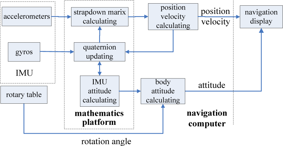
The computation scheme of the rotational SINS
In this paper, the coordinate systems are defined as follows: the inertial coordinate system is the reference coordinate for the inertial components, denoted by i; the navigation coordinate system is chosen as the local east-north-up (ENU) coordinate, denoted by n; the body coordinate system is vehicle-carried and denoted by b; the rotary table coordinate system is fixed with the rotary table and denoted by r. Take the gyros' errors for example, the principle behind the rotation auto-compensation technique can be simply explained as follows: the errors of the three gyros are denoted by ε
r
; the rotation rate of the rotary table is denoted by ωc; and then the projection of ε
r
on the n-frame can be expressed by:

3. Error modelling of the rotary table
For the rotary table in a rotational SINS, there are three main types of errors: installation error, wobble error and angular error. In this section, the physical causes of these errors are analysed and then models are established.
3.1 Modelling of the installation error
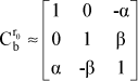
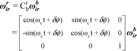
The vertical axis of the rotary table should be parallel to the vertical axis of the body, which means that the z-axis of the r-frame should coincide with the z-axis of the b-frame. However, there exists an error angle due to the installation technology, which is called the ‘installation error’. Assuming that the r0-frame is the coordinate system coinciding with the initial r-frame, then the transition matrix from the r0-frame to the r-frame can be written as:


3.2 Modelling of the wobble error
The vertical axis of the table board The wobble error of the rotary table


According to the relation between the quaternion and the transition matrix, Crb can be written as:


3.3 Modelling of the angular error
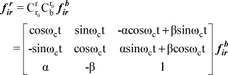
From Figure 2, it can be seen that after solving the attitude of the IMU, the rotation angle of the rotary table is needed to get the attitude of the vehicle. However, there exists an error in the rotation angle, which is called the ‘angular error’ and mainly comes from two aspects: one concerns the errors from the angular measuring device of the rotary table; the other is caused by the desynchronizing between the rotary table and the SINS, which means that the angle value transmitted to the SINS does not match the values of the inertial components. Usually, the maximum angular measuring error is given by the introduction of the rotary table and the desynchrony error can also be expressed by a constant value; accordingly, the angular error of the rotary table is expressed by a constant value δφ in this paper. Next, the transition matrix from the r-frame to the b-frame can be written as:


4. The effect of the rotary table's errors on navigation accuracy
In this section, the effects of the rotary table's errors on position accuracy and attitude accuracy will be analysed and formulae will be derived.
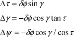
4.1 The effect of the installation error
The installation error changes the relative attitude between the IMU and the vehicle and has no effect on the IMU position-solving. From Figure 2, it can be seen that the rotational SINS's position is equal to the IMU's position, so the installation error does not affect position accuracy.
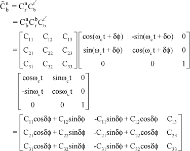
From Figure 2, it can be seen that during the attitude solution process, the transition matrix from the b-frame to the r-frame is needed to get the vehicle attitude from the IMU attitude. But, according to the analysis of Section 3.1, the transition matrix is affected by the installation error, and so the attitude accuracy is also affected by the installation error.
The attitude of the vehicle is denoted as follows: the pitch angle is τ, the roll angle is γ, and the heading angle is Ψ. Then, the transition matrix from the b-frame to the n-frame can be expressed by [21]:


4.2 The effect of the wobble error
As with the installation error, a new velocity/position error is not introduced by the wobble error. However, it can be seen from Eq. (13) that the transition matrix from the r-frame to the b-frame is affected by the wobble error, so the attitude accuracy is affected. Similar to the derivation in Section 4.1, the calculated C˜bn can be derived as:


4.3 The effect of the angular error
It can be seen from Figure 2 that the rotation angle has nothing to do with the position solution, so its error does not affect the position accuracy. However, the rotation angle is needed in the attitude calculation process, so its error affects the attitude accuracy. Similarly with the derivations in Section 4.1 and 4.2, the calculated C˜bn can be derived as:

5. Simulation results and discussion
From the above analysis, it can be concluded that the rotary table's errors have no effect on position accuracy and that only the installation error, the wobble error and the angular error affect attitude accuracy. In this section, the effects of the rotary table's errors to attitude will be simulated and the simulation results will be compared with the theoretical ones. In order to verify the derived formulas, the simulation conditions are set as follows:
The rotary table rotates the IMU back and forth in azimuth through four positions (0 deg., 90 deg., 180 deg., 270 deg.). The dwell time for each position is 290 seconds and the rotation rate is 10 deg./s, so a complete rotation period is 20 minutes. In order to directly reflect the effect of the rotary table's errors, the other errors (such as the inertial components' errors and the initial alignment error) are not considered in the simulation. From Eqs. (24), (28) and (31), it can be seen that the attitude errors are related to the vehicle's attitude. So, in the simulation, the vehicle's attitude varies as shown in Figure 4: the roll angle increases to 30 degrees at a speed of 6 deg./s at 500 seconds, the pitch angle increases to 30 degrees at a speed of 6 deg./s at 1100 seconds, the pitch angle decreases to 0 degrees at a speed of −6 deg./s at 1700 seconds, and the roll angle decreases to 0 degrees at a speed of −6 deg./s at 2300 seconds. The total simulation time is 3600 seconds and the velocity of the vehicle is maintained at zero throughout the whole simulation. Both the rotational SINS with a perfect rotary table and the one with an imperfect rotary table are simulated. The attitude error response to the rotary table's errors is acquired by comparing the attitude results of the two systems. Next, the predicated errors calculated by the error model derived in the paper are compared with the simulated ones so as to verify the correctness of the theory.

The true attitude in the simulation
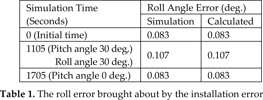
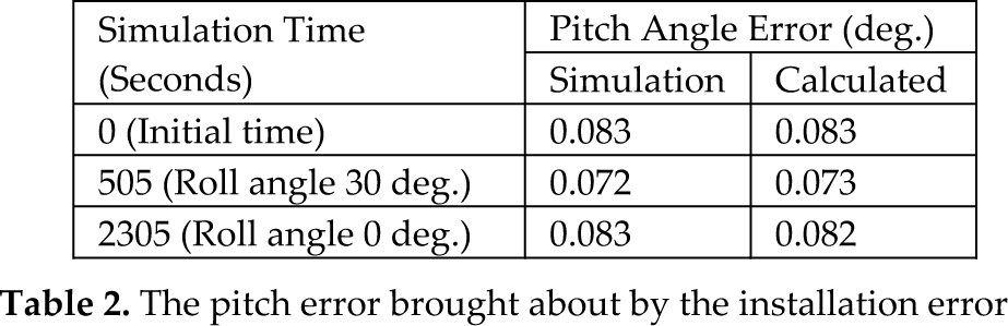
According to the analysis in Section 3.1, the installation error can be expressed by two parameters α, β. In the simulation, the two error angles are both set at 5 minutes of angle, which corresponds to low installation accuracy. The attitude errors of the rotational SINS are shown in Figure 5 and the specific results of some special time points are referred to in Table 1, Table 2 and Table 3. It is clear that the calculated values agree well with the simulated values and that the attitude errors reach 0.1 degrees under the simulation conditions.
The roll error brought about by the installation error
The pitch error brought about by the installation error
The heading error brought about by the installation error


The attitude errors brought about by the installation error
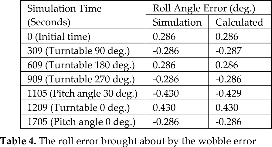
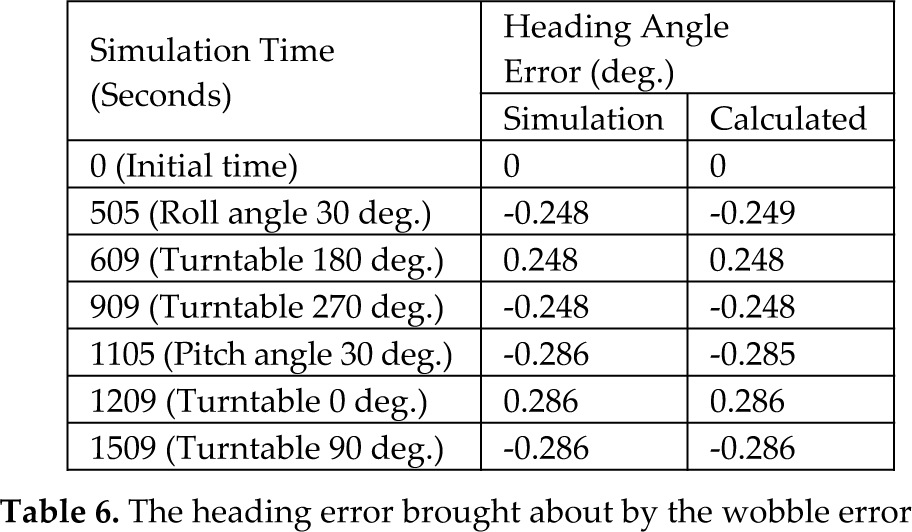
The diameter of the table board is assumed to be 100 mm and the maximum vibration amplitude is set as 1 mm, which represents low machining accuracy. Next, from Section 3.2, it can be seen that the half-cone angle is θ =1/100rad = 0.01rad. Without loss of generality, the initial installation angle η is set as 30 degrees. The attitude errors are shown in Figure 6. It is clear that the calculated values agree well with the simulated ones, and the attitude errors almost reach 1 degree under the simulation condition, which greatly decreases the attitude accuracy. There are several spikes in the curves of Figure 6 corresponding to the rotation process which can be seen in detail in Figure 7. This is because the attitude errors are related to the rotation angle, as shown in Eq. (22). The specific results of some special time points are referred to in Table 4, Table 5 and Table 6.
The roll error brought about by the wobble error
The pitch error brought about by the wobble error

The heading error brought about by the wobble error
The angular error is set as 1 minute of angle, which corresponds to a low-accuracy rotary table. The attitude errors are shown as in Figure 8. The specific results of some special time points are referred to in Table 7, Table 8 and Table 9. It is clear that the calculated values agree well with the simulated values and the attitude errors are less than 0.02 degrees under the simulation conditions.
The roll error brought about by the angular error

The pitch error brought about by the angular error

The heading error brought about by the angular error


The attitude errors brought about by the wobble error
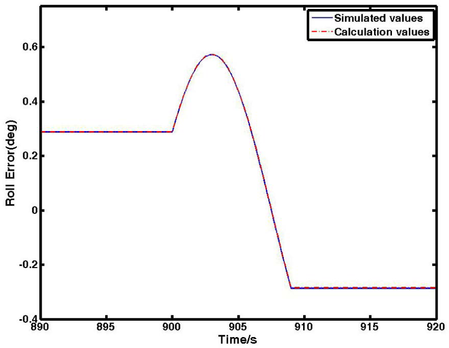
A detailed curve of the roll error brought about by the wobble error

A detailed curve of the roll error brought about by the wobble error
From the above simulation, it is clear that the derived formulas can well describe the attitude errors brought about by the rotary table's errors. Under the simulation conditions, the wobble error has the greatest impact on attitude accuracy.
6. Conclusions
The decrease in the accuracy of a rotational SINS caused by its rotary table's errors is analysed in this study. The rotary table's errors are classified according to three types: installation error, wobble error and angular error. The effects of these errors on navigation accuracy are analysed and simulations are carried out. From the theoretical analysis and the simulation results, the following conclusions can be drawn:
The rotary table's errors do not affect the position accuracy of the rotational SINS. However, the installation error, wobble error and angular error have an influence on attitude accuracy. The attitude errors brought about by the installation error, wobble error and angular error are related to the vehicle's attitude. Moreover, the attitude errors brought about by the wobble error are related to the rotation angle.
The derived propagation formulae of the rotary table's errors supply a good reference for the analysis of the navigation accuracy of a rotational SINS. Furthermore, the theoretical results could serve as the basis for the design of a rotational SINS's rotary table and are especially useful for low-cost MEMS rotational SINSs, which could become widely used in robots, intelligent vehicles and UAVs in the future.
Footnotes
7. Acknowledgments
This work was supported by National Natural Science Foundation of China (91016019, 61174197) and the funding of the Jiangsu Innovation Programme for Graduate Education (CXLX11_0201), the Outstanding Doctoral Dissertation in NUAA (BCXJ11–04) and the Priority Academic Programme Development of Jiangsu Higher Education Institutions.