
Abstract
China is currently building the largest single dish radio telescope in the world, which is called the Five-hundred meter Aperture Spherical radio Telescope (FAST). The feed support system in the FAST is composed of a cable-driven parallel manipulator, an A-B rotator, and a Stewart platform. Since the stiffness of the cable-driven parallel manipulator is low, the feed support system is prone to vibrate under the action of the Stewart platform. The main purpose of this paper is to study the self-excited vibration of the feed support system. Self-excited vibration involves the natural frequencies of the system and the resultant forces produced by the motion of the Stewart platform. This paper linearizes the dynamic equations of the system at an operating point and determines the configuration-dependent natural frequencies in the given workspace. This paper obtains the resultant forces from the legs due to the motion of the Stewart platform by using the numerical method. According to the natural frequencies and the resultant forces, the condition of self-excited vibration is given and verified by simulations. In order to verify the linearization method, an experimental platform of a cable-driven parallel manipulator is set up. The experimental results match well with the theoretical arithmetic. This paper provides a reference point for further studies on vibration suppression in the FAST.
Introduction
In 1994, Chinese astronomers began the conceptual design of the Five-hundred-meter Aperture Spherical radio Telescope (FAST) [1–2]. After more than ten years of efforts, the layout design of FAST has been completed. The FAST project is now in the process of being constructed and completion is planned for 2016.
The FAST is composed of a reflector and a feed support system (FSS), as shown in Figures 1 and 2 [3–4]. The FSS contains three mechanisms which are arranged in series: a cable-driven parallel manipulator, an A-B rotator, and a Stewart platform. The individual cable-driven parallel manipulator [9–11] and Stewart platform [5–7] have been widely studied by researchers. The FSS is a typical multi-level manipulator system [8]. The cable-driven parallel manipulator and the A-B rotator provide the receiver with coarse positioning, and the Stewart platform is used to compensate for the positioning error to achieve the required accuracy. Since the cable-driven parallel manipulator is a long-span flexible cable structure, the FSS raises the concern of possible vibrations resulting from wind disturbance. Besides, as the payload is about 3000kg, according to the conceptual design, the compensation motion of the Stewart platform may induce vibration in the FSS due to the reaction force, which is a kind of self-excited vibration [3]. So far, considerable efforts have been devoted to the FAST, regarding the dimension optimization [9–10], workspace analysis [11], and vibration suppression [12–16]. Previous research mainly focuses on the vibration of the FSS caused by the wind without considering self-excited vibration. This motivates the research in the paper. This paper is mainly focused on the study of the self-excited vibration of the FSS. The results of this study can be used as guidelines for the vibration suppression of FAST.
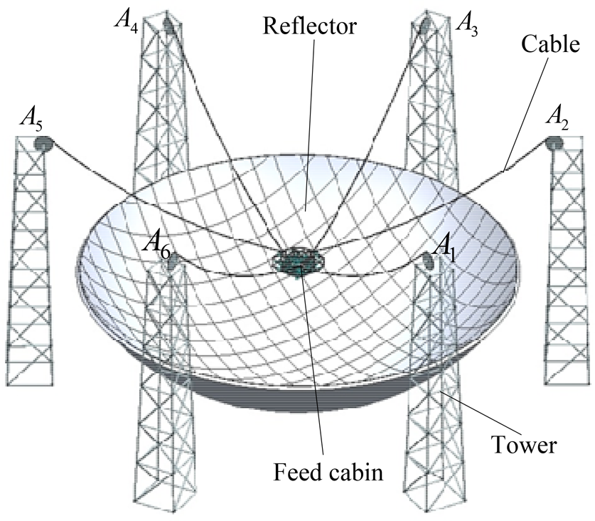
The sketch map of the FAST

The sketch map of the feed support system
In order to analyse the dynamic process, first the dynamic model of the FSS needs to be deduced. Based on different principles of mechanics, there are several methods for establishing the dynamic model, such as the Newton-Euler method [17], the Tagrange formulation [18], the principle of virtual work [19], and the Kane method [20]. Most previous work deals with parallel mechanisms mounted on a fixed base. However, the Stewart platform of the FAST needs to be modelled on a free-floating base, which is more complicated. Based on vector mechanics, the Newton-Euler method, which has the advantage of having clear physical meaning is adopted in this article.
As is well known, the vibration characteristics of a manipulator are closely related to the natural frequencies of the manipulator. Due to the highly nonlinear properties of the parallel mechanism, it is impossible to derive the natural frequencies directly from the nonlinear dynamic equations. Two methods are used to determine the natural frequencies: the Finite Element Method (FEM) [21] and the Linearization method [22–25]. The Linearization method which linearizes the dynamic equations at an operating point to calculate the natural frequencies is more appropriate for obtaining the natural frequency distribution in the whole required workspace. Then, the parameters of the FSS are optimized on the basis of the 1st order of natural frequency.
The reacting force resulting from the motion of the Stewart platform has a great influence on the vibration of the FSS. The inverse dynamics discusses the relationship between the kinematics of the platform and the driving forces of the legs [26–27]. However, the resultant forces from the six legs play a role in the vibration rather than the driving forces, since the driving forces are the internal forces which exist in the two parts of the legs.
This paper is organized as follows. Sec. 2 describes the FSS in detail. Sec. 3 presents the FSS dynamic model. Sec. 4 linearizes the dynamic equations to attain the natural frequencies. On this basis, the parameters of the FSS are optimized. Sec. 5 provides the conditions for the self-excited resonance of the FSS. In sec. 6, experiments have been done on the experimental platform of the cable-driven parallel manipulator to verify the validity of the linearization method. Finally, conclusions are drawn in sec. 7.
As shown in Figure 1–4, each cable of the cable-driven parallel manipulators connects the tower point
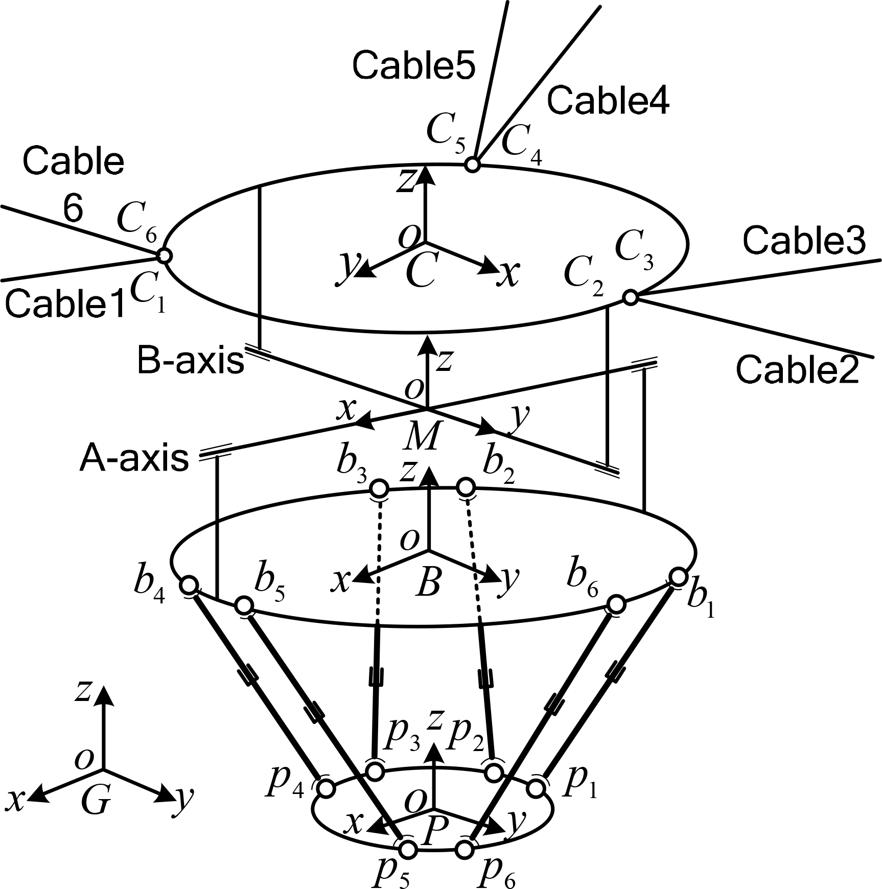
Kinematics notation of the FSS

Joint distribution of the FSS
The required workspace of the feed support system is a spherical crown with a radius of 159.9m shown in Figure 5. The centre of the sphere is concentric where the reflector and the maximum pose angle of the sphere crown are 40 degrees. The normal vector of the stabilized platform needs to pass through the sphere's centre in the required workspace. According to the results of the cable force optimization [9], the relationship between the natural pose angle of the cable-driven parallel manipulator and the measured pose angle is prone to occurring as shown in Eq. (1), while the deviation angle is compensated for by the A-B rotator.

where φ cable is the natural pose angle of the cable-driven parallel manipulator; φ receiver is the measure pose angle.
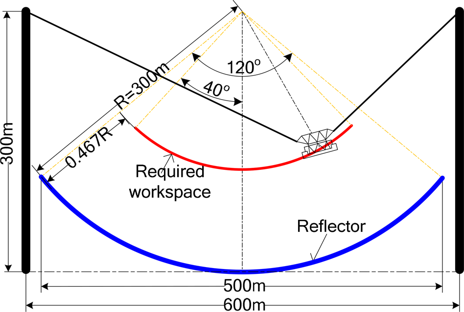
The required workspace of the FAST
The main structural parameters of the FSS are shown in Table 1 [3] and the inertial parameters are listed in Appendix A. At the initial state, the cable platform is at the centre of the required workspace where the stabilized platform is 159.9m below the centre of the reflector, the rotation angles of the A-axis and B-axis are both zero, and the stabilized platform is 2.923m below the base platform.
Structural parameters of the FSS

Some important notations used in this paper are as follows:
G
According to the study in [22], the transversal vibration of cables contributes little to the vibration of the end-effector. So we model the cable as the spring damper, ignoring the transversal vibration, as shown in Figure 6. The force acting on the cable platform from the cable can be calculated in terms of the cable's elastic deformation and velocity as

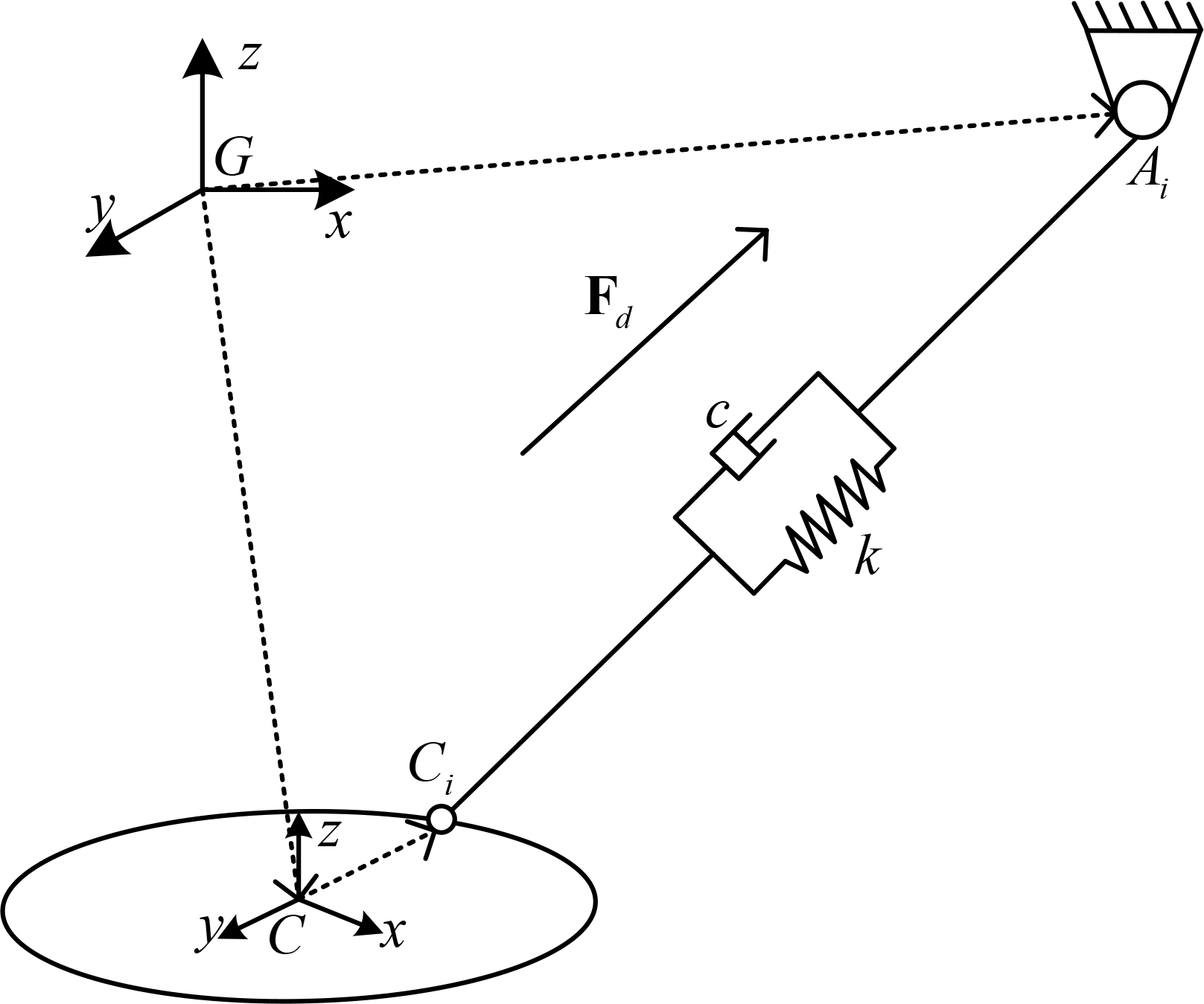
Dynamics notation of the FSS
In the above equations,
According to the Newton-Euler method, the dynamic equations of the feed support system can be attained as
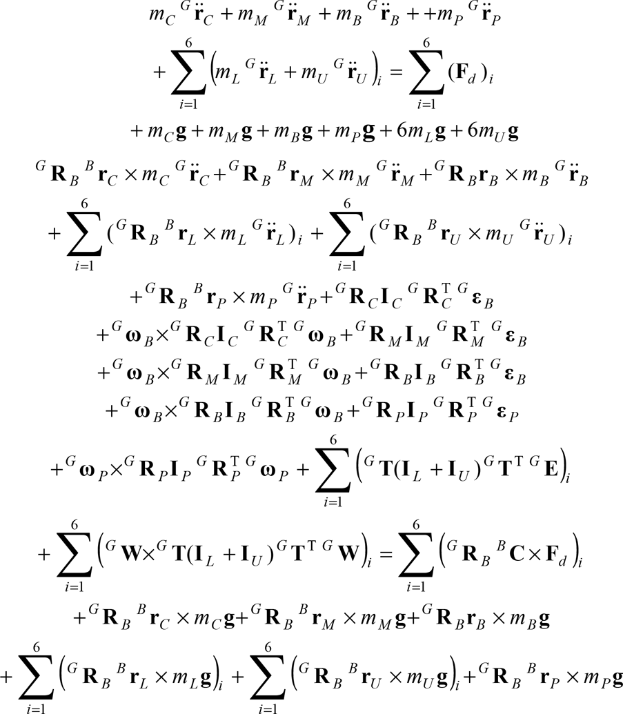
where mC, mM, mB, mL, mU, and mP are the mass of the cable platform, the A-B rotator, the upper part of the leg, the lower part of the leg and the base platform;
The natural frequency is impossible to attain directly, since the dynamic equations are highly nonlinear as shown in Eqs. (3). The linearization method is to be adopted in this paper. Eqs. (3) can be written in a compact form by isolating
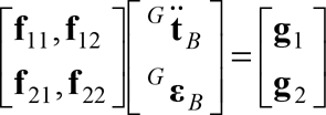
The expression for
Taking the position, orientation, linear and angular velocities of the base platform as state variables

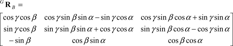
where α, β, and γ are pose angles, which form the orientation
G
The linearized equations can be obtained by expanding the nonlinear Eqs. (4) in the Taylor series regarding the equilibrium position and orientation. By ignoring the high order terms, the linearized equations of motion regarding the equilibrium can be represented as

The expression for
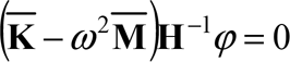
The natural frequency ω and the associated modal coordinates φ of the feed support system can be obtained by solving Eqs. (8). As shown in Appendix B, the mass matrix
Natural frequencies and modal coordinates at the initial state

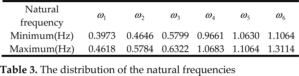
Then, the natural frequencies of the feed support system in the required workspace are shown in Figure 7 and the distribution is listed in detail in Table 3. It is shown that the 1st–3rd order natural frequencies are close to each other and are the same as the 4th–6th order natural frequencies. The 1st order natural frequency is larger when the FSS is in the centre rather than at the border. Since the mechanical structure is symmetrical about the centre, the distribution of the natural frequencies is also symmetrical about the centre.

a. The 1st–3rd order natural frequencies in the workspace; b. The 4th–6th order natural frequencies in the workspace
The distribution of the natural frequencies
According to the vibration theory, the 1st order natural frequency is prone to being excited when the frequency of the disturbance is quite low. During the design of the FSS, we should choose the proper parameters to keep the 1st order natural frequency as big as possible. Two parameters will be optimized: the distributed radius of the tower r1 and the tower height

a. Influence of tower height on the first order frequency; b. Influence of distribution radius on the first order frequency
As shown in Figure 8 (a), the smaller tower height has a larger natural frequency when the FSS is in the centre of the required workspace. However, when the tower height is less than 270m, the natural frequency decreases rapidly at the border of the required workspace. Therefore, the tower height
As shown in Figure 8 (b), different distribution radiuses have a similar natural frequency when the FSS is in the centre of the required workspace. While a larger distribution radius has a larger natural frequency when the FSS is in the middle of the required workspace. However, when the distribution radius is larger than 300m, the natural frequency decreases rapidly at the border of the required workspace. Therefore, the distribution radius r1 is designed to be 300m.
The fine adjustment and vibration suppression of the Stewart platform lead to a variation in the force between the legs and the base platform which results in the feed support system vibrating. The resultant forces from the six legs can be equivalently simplified to the principal vector (inertia force) and principal moment (inertia torque) acting on the base platform with respect to the frame {B} as

where
According to Eqs. (9), the inertia force and the inertia torque are correlated with the mass, moment, pose, velocity and acceleration of the stabilized platform. Numerical simulations are carried out to analyse the relation between the resultant forces and the motion of the Stewart platform. The velocity trajectory of the stabilized platform is shown in Figure 9. When the stabilized platform moves, the inertia force and inertia torque are shown in Figure 10.

Velocity curve of the stabilized platform

a. Inertia force and torque along the x -axis; b. Inertia force and torque along the y -axis; c. Inertia force and torque along the
As is shown in Figure 10, movement along the x -axis can lead to a great X component of the inertia force and a great Y component of the inertia torque. Similarly, movement along the y -axis corresponds to the Y component of the inertia force and the X component of the inertia torque; movement along the z -axis corresponds to the Z component of the inertia force but has only a small effect on the inertia torque; rotation around the x -axis corresponds to the Y component of the inertia torque and both the Y component and the Z component of the inertia force; rotation around the y -axis corresponds to the X component of the inertia torque and both the X component and the Z component of the inertia force; rotation around the z -axis corresponds to the Z component of the inertia torque and all the three components of the inertia force.
The FSS is found to be a multiple degree of freedom vibration system as shown in Eqs. (7). The inertia force and inertia torque that satisfy the frequency and the corresponding modal coordinates can create resonance in the FSS. Several motion excitations of the Stewart platform can result in resonance in the FSS such as:
movement along the x -axis or rotation around the y -axis close to the 1st order frequency; movement along the y -axis or rotation around the x -axis close to the 2nd order frequency; movement along the rotation around the movement along the movement along the y -axis or rotation around the x -axis close to the 6th order frequency.
To justify the above conditions of resonance, numerical simulations will be carried out with the help of the Eqs. (4) in Section 3. When the FSS is at the centre of the required workspace (0,0,159.9)m, the 1st order natural frequency of the FSS is 0.4618Hz. When the Stewart platform moves along the x -axis at sinusoidal velocity (0.4618Hz), the vibration of the FSS is shown in Figure 11(a). Similarly, we can simulate the five other order resonances as shown in Figure 11(b)–(f). This shows that the vibrations are divergent with the natural frequencies.

a. First order resonance (0.4618Hz), b. Second order resonance (0.4646Hz), c. Third order resonance (0.6322Hz), d. Fourth order resonance (1.0683Hz), e. Fifth order resonance (1.1006Hz), f. Sixth order resonance (1.1064Hz)
The first order resonance of the FSS at the half cross section of Y=0 m in the required workspace are shown in Figure 12. Only vibrations along the x -axis and around the y -axis are plotted as they are greater. They indicate that the resonance exists in the whole required workspace.
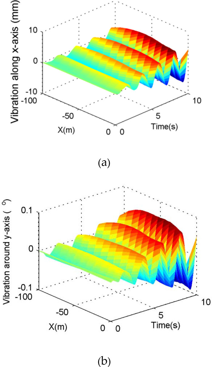
The first order resonance. a Vibration along the x -axis; b Vibration around the y -axis
Above all, the FSS tends to resonate if the motion frequency of the Stewart platform is close to the natural frequencies of the FSS. Therefore, for the sake of vibration suppression, the motion frequency of the Stewart platform should not fall near the natural frequency range. Otherwise, the compensating system may vibrate and became uncontrollable.
An experimental platform of the cable-driven parallel manipulator is designed and constructed to verify the natural frequencies as shown in Figure 13(a). The experimental platform consists of the cable platform, the base platform and six cables. The additional weight fixed on the cable platform can enhance the cable forces. A force sensor with a sampling frequency of 400Hz is used to measure the cable tension. mi is the connecting point of the cable and the base platform, and ni is the connecting point of the cable and the cable platform. Let {M} be the base platform frame, attached to the centre of mi with the x -axis crossing the midpoint of m1m6 and the

a. The experimental platform; b. The structural parameters
The cable platform will perform free damped vibration as a result of the impact force. The force sensors record the vibration of the cable platform. Then, we can obtain the frequencies of the experimental platform by the power spectrum density (PSD) of the force sensors. Since the higher order natural frequencies are hard to excite, we can only get the first two order natural frequencies through these experiments. Moreover, it is only the first two order natural frequencies that make sense, according to the practical application of the FAST.
The pose of the cable platform in {M} can be derived from the length of the six cables as follows

The first two order frequencies and their associated modal coordinates are determined using Eq. (7) in Section 4 and are shown in Table 4. Here the stiffness of the cable can be attained by k = E · A / L. It is assumed that all the cables have the same elastic modulus (E) of 0.4×10¹¹ Pa and sectional area (A) of 3.1416×10⁻⁶ mm.
Natural frequencies of the experimental platform
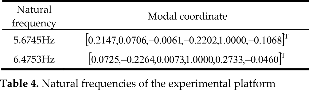
Table 4 indicates that the first order modal coordinate vibrates mainly along the x -axis and around the y -axis. If an impact force is imposed on the cable platform along the x -axis, the cable platform will vibrate at the first order frequency and slowly dampen as shown in Figure 14 (a). Similarly, the cable platform will vibrate at the second order frequency under the impact force along the y -axis as shown in Figure 14 (b). In order to attain the first two order frequencies, a power spectrum density (PSD) of the time-domain experimental data is performed using MATLAB tools as shown in Figure 15. The two transformation results are drawn in one figure for the sake of comparison. Furthermore, the PSD values ranging from 20Hz to 200Hz are close to zero and are omitted. It can be seen from Figure 15 that the peak value of the plots corresponding to the impact along the x -axis is 5.7617Hz and impact along the y -axis is 6.5430Hz. It means that the first two order frequencies are 5.7617Hz and 6.5430Hz based on the experiments. Therefore, the linearization method used to determine the natural frequency proposed in this paper is validated since the theoretical results listed in Table 4 match well with the experimental results.
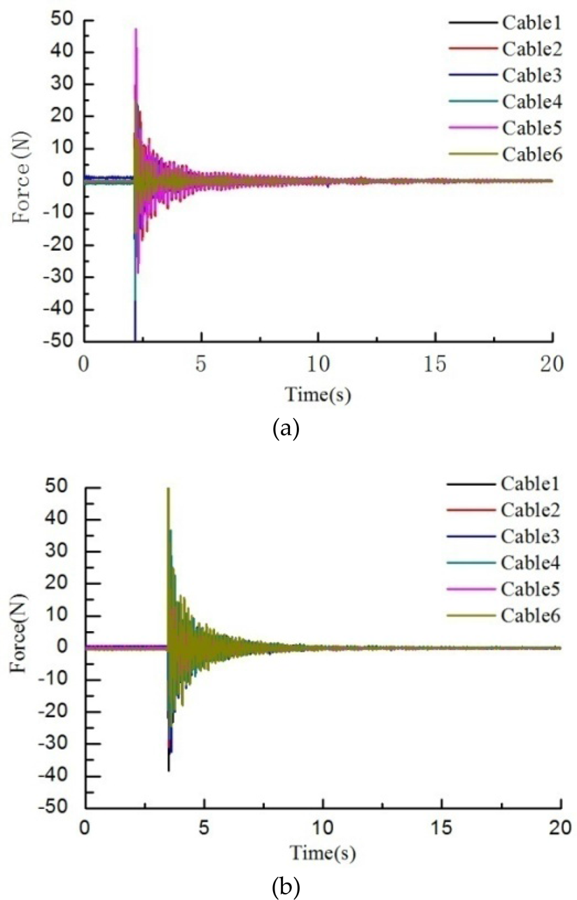
a. Cable forces under the impact along the x -axis; b. Cable forces under the impact along the y -axis

Power spectrum of the cable forces
In this paper, a generalized dynamic formulation of the FSS is developed by using the Newton-Euler approach. The linearization method is applied to the dynamic equations to attain the natural frequencies and is verified through experiments. Numerical simulations are carried out to determine the resultant forces from the legs. Then, the condition of self-excited resonance is presented and validated by simulations. Therefore, we can draw the following conclusions:
The natural frequencies of the whole required workspace are calculated by the linearization method. The lowest (1st order) natural frequency range is from 0.397Hz to 0.462Hz. On the basis of the 1st order natural frequency, the parameters of the FSS are optimized. The conditions for self-excited vibration are provided. In order to avoid inducing self-excited vibration in the FSS, the motion frequency of the Stewart platform should be kept away from the natural frequency ranges of the FSS. According to the power spectrum density (PSD) of the time-domain experimental data, the natural frequencies of the cable-driven parallel manipulator are acquired, which verify the feasibility of the linearization method.
The study in this paper provides theoretical foundations for further vibration suppression methods for the FAST.
Footnotes
8.
This research is sponsored by the National Natural Science Foundation of China (No. 11178012, 51205224) and National Natural Science Funds for Distinguished Young Scholars of China (No. 51225503).
Appendix A: Parameters of the FSS
All the parameters in Appendix I are the default in SI units.
The mass, position vector of the centre of mass and the moment of inertia of the cable platform:
The mass, position vector of the centre of mass and the moment of inertia of the A-B rotator:
The mass, position vector of the centre of mass and the moment of inertia of the base platform:
The mass, position vector of the centre of mass and moment of inertia of the upper part of the legs:
The mass, position vector of the centre of mass and the moment of inertia of the lower part of the legs:
The mass, position vector of the centre of mass and the moment of inertia of the base platform:
The mass, position vector of the centre of mass and the moment of inertia of the experimental platform:
Appendix B: Expression in detail