
Abstract
The Building Information Model (BIM) serves as a framework to align all the project-related data, providing interoperability to store and retrieve information interactively. Unfortunately, the construction site itself is excluded from this interaction as the large amount of data requires high data transfer rates and ruggedized hardware. However, advanced wireless communication technologies open radically new avenues to relay large amounts of data automatically and in near real-time. Construction could be a key beneficiary of these advancements. Wireless communication integrated with BIM, GPS and the Internet is able to provide the backbone necessary for creating intelligent systems, supporting the designer in his or her office as well as workers on the work-front. This paper presents a study that documents the development and testing of prototypes designed to facilitate information sharing at the field-level during construction. The main system constitutes an information hub, called the eCKiosk, connecting “senders and receivers” both on-site as well as off-site. The system design is discussed and some of the main modules are demonstrated. Since the electronic Kiosk depends on robust connections to the wireless devices distributed across the site, reliable connectivity is essential. For this reason, the discussion includes a study of the electronic signals behaviour in an ever-changing construction site. Measurements of the signal strengths during excavation and concrete work are presented and compared with theoretical calculations used to predict wave propagation. The results show how present models overestimate signal attenuation patterns on the construction site. This is important for designing a reliable and secure wireless site networks to link BIM to the work-front.
1. Introduction
Significant advancements in the field of smart mobile devices over the past decade have led to the integration of IT with several business/manufacturing systems. The capabilities offered by wireless communication - such as the iPhone - have played a key role in the fast rate of IT adoption rate. Tasner et al. [1] showed that still further improvements are possible. They argue that improved connectivity will open the door for higher levels of data transfer efficiency, data processing, evaluation and logging. Because of the complexity of worksites, the construction industry has been among the late adapters of IT. Indeed, IT is mainly found at the managerial-level rather than at the field-level [2].
IT has been found effective in managing the large amounts of data needed for complex construction projects. In addition, the Building Information Model (BIM) is able to bridge the many disconnections between the various software packages and standards. While the adoption of BIM is still growing, its use is limited to design and planning, excluding information as to how the electronic BIM is to be turned into physical reality. It is not surprising that manual paper-based blue-prints of drawings are the state of the art in the field. To establish digital records of what actually has been constructed, several efforts have been made utilizing technologies, such as Lidar to, for example, measure excavated soil volumes [3–4]. Nevertheless, we lack a data acquisition system capable of automatically collecting and processing information that can be fed into the Live BIM (L-BIM) in a timely and reliable manner. One key technical barrier is the lack of a communication network able to carry the large amount of data with sufficient speed across the construction site. However, this barrier has been removed by advances in wireless technologies and particularly in increased wireless data transfer rates. iHelemt [5] is an example of ongoing efforts to facilitate BIM retrieval at the worksite. Bae et al. [6] developed Hybrid Four-dimensional Augmented Reality (HD4AR) tools to be used on real-world construction sites to streamline automated, on-demand and inexpensive access to project information. Irizarry et al. [7] have prototyped Information Surveyed Point for Observation and Tracking (InfoSPOT), which provides interactive access to BIM corresponding to the user's situation at the building site. The Head Marker Tracking Augmented Reality (HMTAR) system [8] can be customized to exchange BIM at the worksite. However, a BIM-allied worksite needs customized BIM tools to enclose various information sources requiring extensibility and configurability [9]. Chi et al. [10] discussed how the advancement of IT tools will provide flexible information platforms to access BIM information in the field. Wu et al. [11] emphasized the lack of an on-site information management platform that embraces all real time information. However, [12] demonstrated the potential of the fusion of augmented reality, a business social networking service and BIM in providing the basis for in-use applications. Similarly, [13] designed a template to proactively identify construction defects using BIM and automated field inspection.
Another area depending upon real-time data communication is on-site automation and robotics. The existing prototype systems have to be considered ‘islands’ of communication. For example, the robotic pipe-laying system “PipeMan” [14] can automatically create “AS-BIM” data with the exact location of each pipe before backfilling the trench. Similarly, the cable-based robotic platform for construction in [15] and the on-board backhoe monitoring system in [16] could greatly increase safety and productivity. Of course, the mobility of these automotive machines requires wireless control and monitoring. Because of this, telematics and telemetry rely on a robust wireless network to collect, communicate and receive electronic data. Distance measurement is not a new concept, but its ‘marriage’ with construction technologies would be well-suited to serve as a promising achievement towards reliable, error-free, automated process implementation and control. Automatic as-built generation with utility trenchers is a good example of integrating telemetry and operating machinery to record the real-time “AS-BIM” of newly-laid phone or power cables [17]. Bernold et al. [18] have also emphasized the secondary application of teleported systems in equipment operator-training.
The following section presents the concept of a BIM that is integrated with an on-site communication backbone. This will be followed by the introduction of practical issues involved in actualizing the BIM's dissemination through a prototype electronic construction kiosk (eCKiosk). The results of measuring the WiFi signals during construction are summarized in Section 4.
2. Review of the BIM Framework
The National Institute of Standards and Technology [19] reported the cost of inadequate interoperability among separate applications to be $15.8 billion per year in the US capital facilities industry alone. Coupling ICT within ad hoc individual applications targeting only one phase of a project lifecycle has transformed ways of representing building information, such as two-dimensional drawings, perspectives, engineering calculations, quantities, management networks and costs [20]. Afterwards, BIM arose from the need to develop an integrated single framework to describe all the relevant information throughout the whole project lifecycle. The National Institute of Building Science (NIBS) [21] defines BIM as “a digital representation of physical and functional characteristics of a facility. As such it serves as a shared knowledge resource for information about a facility forming a reliable basis for decisions during its lifecycle from inception onward.” Design, engineering and purchasing functions stored in BIM can be used to verify, guide and track field-level processes. Azhar et al. [22] mentioned: a) visualization, b) fabrication/shop drawings, c) code reviews, d) forensic analysis, e) facilities management, f) cost-estimating, g) construction sequencing, and h) conflict, interference and collision detection, as the applications of BIM. Ballesty et al. [23] summarized BIM's benefits as: a) the accurate geometrical representation of the parts of a building in an integrated data environment, b) faster and more effective processes of information, c) better design, d) controlled whole-life costs and environmental data, e) better production quality, f) automated assembly, g) better customer service, and h) lifecycle data.
2.1 Synergizing BIM
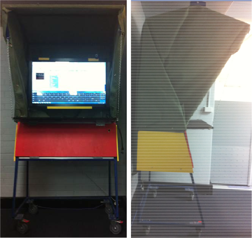
FIATECH [24] has predicts that construction sites will be more intelligent as materials, components, tools, equipment and people become elements of a fully sensed and monitored environment. Facilitated information pull will let each verified user require information from a BIM-supported central information repository. Such on-demand information delivery allows for dramatic productivity improvement. Supplementing a crew with real-time and up-to-date data will reduce idle time, the number of requests for information (RFIs) and rework, thus boosting productivity, quality and safety. Included in such a vision is the automatic updating of the BIM data via electronic field-level data acquisition tools. Of course, having up-to-date data available at all times would offer essential information for managerial decision-making processes. El-Omari and Moselhi [25] conducted experiments with different hardware and software systems to figure out the best combination to create an integrated field data acquisition and automated progress reporting system. The coupling of such a feasible and proven system with BIM synergizes the functionality of both. BIM enhances the sharing of collected data and reduces potential interoperability problems (synergism mode A); equally, a near real-time BIM provides a more realistic image of the project context. Figure 1 depicts how advanced IT can be integrated with BIM to synergize diverse applications. By extending the BIM technology's applicability to the construction process, not only does the managerial-level benefit from it so too would there be added value for the construction crew. Computer-based information-rich BIM supports the crew by enhancing certainty in multiple fields, like planning, safety and resources supply. However, mode B synergism is only contingent if an appropriate medium other than paper is available to facilitate the communication of well-structured BIM across a project network. As mentioned, eCKiosk [26] is the principal user interface linking BIM to the work-front, and to collect data at the same time. Figure 2 depicts the hardware design of the eCKiosk, consisting of a steel structure supporting a sun-protection roof and a 42 inch touch-screen. Special attention has been given to pro-actively address site-related difficulties that might be expected. Some of these features include a touch-sensitive communication interface, a power supply, connectivity, ease of transportation and protection against the harsh environment. Such a new gate will allow for direct and timely access to the BIM data as well as a point from which data can be collected electronically. On the one hand, the end-user can request and receive BIM-compatible information (e.g., the arrival of a truck) via a touch-screen, video, speakers, etc. On the other hand, progress, temperature, wind, changes of orders, etc., can be entered automatically via sensors, the touchscreen, voice or keyboard. Aram et al. [27] investigated the shortcomings of current BIM platforms in communicating information at the process-level and suggested necessary capabilities for BIM tools to more efficiently support and improve field activities. The realization of the value added by eCkiosk is pivotal to the development of platforms beyond the current BIM tools in integrating multiple information streams toward, through and from eCKiosk. To demonstrate the variety of possibilities, a snapshot of eCKiosk is displayed in Figure 3. As can be seen, the touch-screen keyboard at the bottom enables the user to type in any text. A visual representation of the wireless sensor network is displayed on the left-hand side. In this case, the current readings of several thermocouples are gathered via a wireless network and interpreted by LabView code and then expressed in different ways, like graph indicators or numerical indicators, like bars, meters or gauges. An alarm LED will notify the user when each measurement is exceeding a specific threshold. In the middle, the real-time GPS information is presented. This informs the user about the current status of the delivery fleet. Several sorts of information, like real-time position, speed and direction, are provided for the user. If the GPS receivers are used for equipment security (e.g., the concept of a geo-fence), a warning will announce that the equipment is moving out of a predefined area. The Skype windows on the right-hand side allow the user to communicate with every other project participant in order to ask for corresponding information. For example, when a defect is detected, the problem can be described to the designer in real-time while the designer can in turn observe the problem. Then, a decision will be made regarding how to solve the problem.

Synergizing BIM with site-level electronic communication systems
The eCkiosk prototype

A snapshot of touch screen of eCKiosk
Already today, construction sites embrace different electronic systems, like laser scanners, Radio Frequency Identification (RFID), wireless sensor networks (WSNs), Ultra Wideband (UWB), Global Positioning Systems (GPSs) and 360 degree cameras to collect any required data for the purpose of BIM-updating. Other public WSN local databases are other sources to be merged with the site network data. Agents are responsible for data processing to prevent information overflow [28]. Agents communicate with other nodes to exchange information. Successful collaboration relies on the effective communication of data. To achieve this value, the frequently-updated BIM needs to be actively shared among project stakeholders. To survey the feasibility of the implementation of the proposed system, two main functions were examined. Firstly, a security framework to ensure safe information flow and, secondly, WiFi network coverage as the main requirement to realize the system of interest. The influence of particular, dynamic conditions of the construction site on the network's performance was investigated.
3. Security for Automated Communication
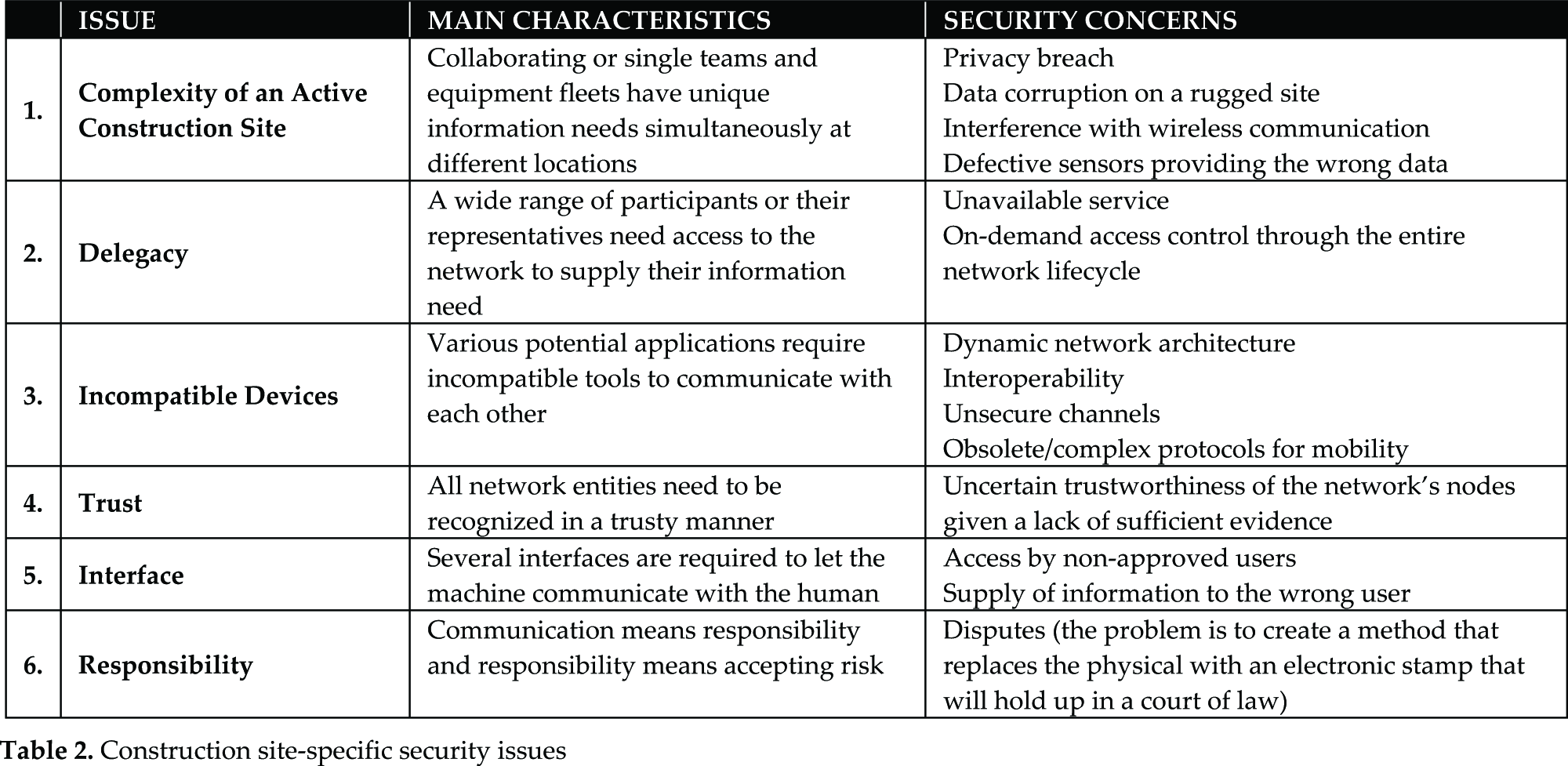
The main function of an electronic communication network in construction is to link the resources involved in a process (e.g., foremen, equipment, electronic sensors, design information) with each other, the process control agent and the project network, including the site office, main office, engineers, and other participants outside the construction site. Because the backbone of a site-based communication network as well as its integrated electronic tools are exposed in the ‘open’ - similar to a battlefield - they have to be protected with a reliable network security system. As depicted in Figure 4, one such concept is the “Security Ring”, inspecting all communications among the participants that pass through the ring. Furthermore, each individual node could be protected by its own unique firewall, intrusion detection system (IDS) and antivirus protection software. Well-known system security threats include: a) Repudiation, b) intrusion, c) spam mail, and d) malicious software including: a) viruses, b) worms, c) Trojan horses, d) logic bombs, e) backdoors, and f) spyware [29]. Not surprisingly, the main objective of the ring is to control the access of individuals and shield against malicious cyber-attacks. The ring's responsibilities in ensuring confidentiality, authenticity, integrity and availability are summarized in Table 1.
Key services provided by security ring


Model of a security ring for protected information sharing
Maintaining connectivity is essential for an effective and ubiquitous information network which faces a broad spectrum of challenging requirements, from management to computational capacity and power. Chao [30] described how the expense for tools to ensure the security of ubiquitous networks now exceeds the equipment's cost by up to 18 times. The establishment of such services on the construction site-level faces its own specific problems, as explained in Table 2.
Construction site-specific security issues
3.1 Security Framework
The security concerns have been clustered into three categories: 1) physical, 2) interface, and 3) network-related (Figure 5). Physical security focuses on keeping

Main modules and relationships of a security framework developed to safeguard the system's performance
the communication hardware working and free from interference. Especially crucial is protection against the ‘threats’ of the harsh construction environment. Equally, power needs to be provided and secured against vandalism and theft. Possible methods include strong-box protection, video surveillance, geo-fencing and WiFi-based tracking. Of course, such protective techniques need to be sufficiently secured against the disclosure of personal information that may breach user privacy. A workers' privacy is easily violated if a camera-equipped network tool is abused. This is why location information should not be disseminated through the network and only authorized entities/agents should have access to this information to protect users against any possible privacy violation.
Interface security controls user login policy. Even some biometric features can be used to determine a user's identity. However, not all logged-in users should have the same access-level. Considering probable changes in crew combination, a role-based access control is necessary. Access to information is restricted according to a user's role in the project. Control of the extent of information detail/brevity corresponding to a particular application is a part of security - for example, drawings with different resolutions are presented for different purposes. Therefore, an interactive information exchange agent adjusts the amount of detail provided to the user. Also, the validity of communicated information which is categorized under information quality control is a complement of interface security. The dispersion of an unverified piece of information may indirectly lead to a security breach. For example, unapproved system shut down notifications may cause data loss.
The network security column comprises issues affecting the reliability of the network, including: data traffic control, required encryption technology to encode and decode data flowing across the network, as well as the network architecture. Network coverage and the configuration of the transmitters, routers and antennae is discussed as a network architecture facet.
3.2 Implementing the Developed Security Framework in Practice
The advent of BIM significantly improved the design and detailing of construction processes, including the rebar supply chain. Efforts continue to be made in exploring different application areas for BIM in construction. However, the currently available BIM platforms are not sufficiently compatible to facilitate every possible application, especially those implemented at field-level. Coordination, integration and the proper preservation of such a platform are key success elements in extending BIM to the worksite. Extensive progress in wireless technologies has opened new avenues in mingling IT with construction processes in order to improve safety, quality and productivity. It goes without saying that the next generation of BIM platforms needs to be developed to accommodate transformed information flow patterns. The following paragraph presents how the proposed security framework has been applied to ensure the reliable use of an IT-based solution to preserve safety in rebar unloading. A Wireless Lift Assist (WLA) was developed to provide crane operator a visual access to work-front. Tests with the WLA were undertaken as a part of a holistic experiment to measure the value of implementing a BIM-integrated rebar delivery management schema on the sub-processes, such as crafting at the fabrication shop, delivery, unloading, site storage and placement. The WLA consists of a wireless IP-camera attached to the crane's hook block which uses the site network to transfer a video stream to a networked screen improvised in the crane cabin. Apparently, the physical security of close to $4,000 worth of gears was a concern in the real-world test. Furthermore, a secure attachment mechanism needed to be designed to firmly hold the accessories on the hook block, the screen on the cabin window as well as the network antennae at appropriate places. Vibration, wind, dust and sunshine were influential factors that the WLA components (particularly the wireless camera) had to be protected against by appropriate housing. Powering the wireless camera was also a part of physical security. An easy-to-replace, rechargeable battery was added to the WLA to power the accessories on the hook block, including a IP-camera, a signal booster and a GPS data logger. Although system login is enforced in interface security, user privacy should not be violated. For example, the log-in status of the crane operator must not be used as an indicator of his presence in the crane cabin. Role-based access is another part of interface security, which adjusts the access of the different users to the collected data. Five typical audiences of WLA are: a) the crane operator via the system's embedded screen; b) the signalmen at the unloading zone via the eCKiosk; c) the site manager via smartphone; d) the BIM agent collecting positional data from the GPS agent to mingle real-time video with virtual reality models developed by an adapted BIM platform for multiple purposes, such as automated progress control, productivity measurement and collision prevention; and e) the project owner (if applicable) via a web-based interface. An interactive input/output is required to collect/deliver the correct combination of available information to the user. Despite overlapping with the role-based access function, the user and the WLA have to interact to balance users' needs and the system's capabilities. For example, both delivery trucks and crane hooks are traceable in real-time using GPS units communicating their location in two different scales. The crane foreman is only interested in the real-time position of the delivery truck so as to schedule the crane assignment. Information quality control is the next component of the framework. Although WLA is capable of providing decent picture quality, in practice the size, resolution and colour of the image have to be adjusted to ensure the successful implementation of the system. Sometimes, quality has to be compromised because of the low data transfer rate. The flawless flow of information in the network is investigated under the data transit category. Each protocol offers different capabilities which significantly affect the rate of data transit and network coverage. The research team observed a meaningful improvement in network coverage, video stream delay and network interruption by upgrading from 802.11g to 802.11n. The selection of appropriate encryption technology protects the network against intrusion and the leakage of confidential information. In Australia, union regulations strictly oppose recording the workers at the site; therefore, reliable encryption is essential to maintain confidentiality, while recording has been enabled by an interactive input/output control. Finally, the network architecture plays a pivotal role in enabling the efficient flow of information and network penetration. The optimum design of ad hoc WLA networking includes an antenna installed on the crane trolley. However, many of the advantages of connecting the WLA to the site network and other technical barriers led to the development of a more complicated network that covers the whole site. The optimum position of an omnidirectional 8 dbi antenna connected to a wireless-n access point was determined to maximize the network coverage. Maximum coverage corresponds to the higher probability of the continuous connectivity of the WLA to the network regardless of the spatial position of the crane hook on the site. An optimum network architecture provided enough coverage, but the wireless camera did not emit strong enough video signals capable of travelling all the way back to the access point. In other words, the camera detected the network in all crane's operational situations but the video stream was not collectable by the access point to be shared through the network. A signal booster was attached to the camera to overcome this drawback. The power emitted from wireless camera was increased from 5.2 μW / cm2 to 104.4 μW / cm2 before and after the booster was applied. Using Equation 4 from Section 4.1.1, the amplified signal travels 2.84 times further in comparison to the original penetration of the video signals.
4. Quantifying Signal Attenuation Behaviour on an Active Site
Wireless technology represents a cost-effective solution to connecting heterogeneous network devices [31]. In fact, real-time operations using wireless systems are now driving research streams to investigate the secondary applications of such a distributed communication network. For example, David et al. [32] introduced a technique to measure atmospheric humidity using data collected by a wireless communication network. However, the size of the coverage area is always a matter of concern in providing reliable service. The performance of a network to accommodate the rapid flow of data is limited because of physical barriers, fading effects, ambient noise and interference from other electromagnetic emission sources. Consider an operating bulldozer and its effect on network performance. Moving equipment effects network performance by blocking line of sight between the transmitter and receiver, as does the electromagnetic field created by the engine in interfering with radio signals. While it is possible to neglect such short-term instabilities, fixed alterations of the environment have to be considered. In fact, dynamic changes in network topology are unavoidable in construction worksites when nodes are added, deleted, substituted or relocated. Dong et al. [33] mentioned signal jamming and interference from close radio frequencies as problems for WiFi functionality. Neither of the existing outdoor or indoor RF signal propagation models fully fit construction worksites, which challenges the industry to develop its own practical model. Some of the features to be included in developing a construction-specific model are: a) considerable background noise levels and interference; b) complex cluttering; c) a dusty environment; d) moving receivers; e) safety regulations and code-related restrictions; f) dynamic site features; and g) exposure to open air and climate issues. The final part of this study seeks to assess WiFi network performance on an active construction site as a basis for designing a reliable network as the project progresses.
4.1 Experiment Strategy and Results
The complexity of construction makes it extremely difficult to model the effect of the many variables - such as the signal strength of a WiFi network - or to predict their behaviour. For this reason, actual measurements conducted in an active construction site is the only reliable approach to study construction specific features such as: a) dynamic topology, b) mobile and temporary installed obstacles, c) high intensity interfering noise, and d) variable height difference between the router and the receiver, on the signal propagation pattern. With the project's progress, signal strength is measured and recorded on a regular basis using a RF field strength meter. Next, a site coverage map is created to compare the influence of different ambient conditions. The selected project is a multi-story accommodation complex for students in UNSW. The measurements were done in two perpendicular directions parallel to the site boundaries. In order to build the power density map, the total area was discretized into smaller cells. The sizes of the cells were determined based on possible physical access and minimum distance as causing significant differences in the read signal level based on device accuracy. Therefore, readings were done along a raster with a non-uniform arrangement of cells. The sides of the rectangular cells varied from 6 m to 30 m in length. Measurements have been done on the corners of each cell and then averaged to represent the power density on that cell. The RF power intensity in μW / cm2 is measured by a three-axis RF field strength meter (TM-195) manufactured by Tenmars. To improve measurement accuracy within the 2.4 GHz range, the calibration factor was set to 0.66 as a means to compensate for the sensitivity of the field sensor in terms of its frequency response. A Matlab program processes the raw data and draws the signal strength contour map. The geographical south-east corner is selected as the origin while south-north is set as the horizontal axis and east-west as the vertical direction. A preliminary site survey identified the location of a WiFi antenna covering the construction site at the western edge. Site surveys were done at breaks to minimize interference.
4.1.1 Quantifying Effect of a Dynamic Topography
Changing ground surfaces are common at the outset of most construction and mining. Thus, one of the first questions focused on how it might impact wireless communication. This was addressed by tracking signal propagation patterns during the excavation of a foundation presented in Figures 6 and 7. Figure 6-a) introduces the situation of the site before the removal of the soil highlighted at the top-view site drawing. The bench height is approximately three metres, acting as a wall that blocks signals ‘travelling’ east. In Figure 6-b), one can recognize that a section has been excavated while the centre is still in place. Because the backhoe dumped some of the soil within its boom reach, the height of the resulting mound is now 6 m and its length 8 m, reaching from x = 60 m to 68 m. By 03/10/2012, Figure 6-c), all the material was trucked off-site. The signal strength measurements were done at the dates indicated in the captions. Figures 7-a), b) and c) present the measured power density contour map across the site during three points in time. At the beginning, the edge of the upper and lower parts (Y=25 m) divides the site into two distinct western and eastern areas. To compare different situations, the total power distributed across the site is calculated based on Equation 1:

Progress of excavating block B

Changing signal strength contours during excavation

where γij is the signal intensity measured at each node.
The total power receiving site at the beginning was 1.16 (W), partial excavation slightly increased it to 1.28 (W), and finishing the excavation increased the total power to 3.43 (W). Incomplete excavation changed the propagation pattern by letting more penetration into the north-eastern area and transferring local pick (0.050 μw/cm2) from very close to the south border to the more central locations. However, a taller (almost double the height) obstruction prevented a dramatic improvement in signal coverage. The significant jump in signal density all across the site is the result of established line of sight in almost the entire area. Interestingly, the flattened surface draws more power from the source with a global maximum three times (0.250 μw/cm2 comparing to 0.070 μw/cm2) greater than the un-levelled condition. This means that even the areas between the access point and the deposited soil (non-faded channels) are affected by the excavation process. It is also observed that the enhanced network is distributed more smoothly over the surface. To assess the validity of the available formulae, the empirical diffraction loss based on ITU for intermediate terrain as expressed [34] in Equation 2 was selected:

in which h is the height difference between the most significant path-blockage and the line of sight (LOS) path between the transmitter and receiver that is measured to be less than a meter and hence in the order of one tenth of meter O(-1). F1 is the radius of the first Fresnel zone and is given by Equation 3:
where d1 and d2 are the distances from each terminal to the blockage in kilometres, d is the distance between the sender and receiver in km, and f is the frequency in GHz. Estimating that in our observation the blockage occurs at the midpoint of the path, d is in the order of hundred meters and then O(-1) kilometer, Ad equals 11.13 (db). The maximum measured diffraction attenuation is 2.77 (db), which means the empirical formula apparently overestimates the actual loss. Free-space loss for the normal site situation was calculated through the path highlighted in Figure 7-c) using Equitation 4.

where PTi is the transmitted power at point i in dbm, n is distance power decay index, and di is the distance between sender and receiver. Therefore, the mean decay index in these experiments is 2.87 (this is independent of frequency).
4.1.2 Measuring the Effect of Operating Equipment
Passing equipment, moving back and forth in its operating cycle, temporally interrupts wireless links. A particular case was observed when a dump truck unloaded soil material to be spread by an excavator. When the line of sight was cut by the truck lifting its bed, the read signal strength at a node right behind the truck dropped from 0.0024 to 0.0014 (μW / cm2). Furthermore, it was observed that the signal strength in the area covered by the excavator was fluctuating in accordance to the different amount of power which was drawn from the hydraulic motor. Figure 8 shows the intensity map when the truck is present and the area of its manoeuvre. Compared to Figure 7-b) where no truck is around, the contours at the faded area were pushed backwards (southwest) and the received power at the affected cell dropped from 0.0081 (W) to 0.0064 (W). This means that the combination of a truck and a working excavator reduced the signal power by 11 (db).

Signal propagation pattern affected by working equipment
4.1.3 Effect of Interfering Noise
IT integration at the field-level demands a reliable short-range communication backbone. However, due to the fast-changing nature of construction activities, the requirements and constraints in establishing a wireless network are extremely tough. One obstacle is the inevitable and various known and unknown forms of interferences. The purpose of this part is to investigate the potential threat of signal interference to a reliability-critical service like that which is proposed in this paper. The exact amount of interference and the noise-to-signal ratio (SNR) is not discussed in this section. The discussion here regards the effect of bi-directional radios used to link personnel across the site, such as signalmen and crane operators. Increased transmitted power does not necessarily mean a network interruption, and this is because of the different operation frequencies of radio and WiFi networks. However, this simple example proves how emissions from various sources may interfere, causing an increase in error probability. The deployed device in these experiments was not able to categorize intensity in separated ranges. What the device actually measured was the total available electromagnetic energy from all possible sources. Figure 9 has the same layout as Figure 7-c), and the only difference is that the survey was done during regular working hours when personnel using radio communicate with each other. Calculations show that the total amount of power transmitted to the site equals 7.13 (W), which is two-times bigger than the 3.43 (W) generated by the WiFi router.
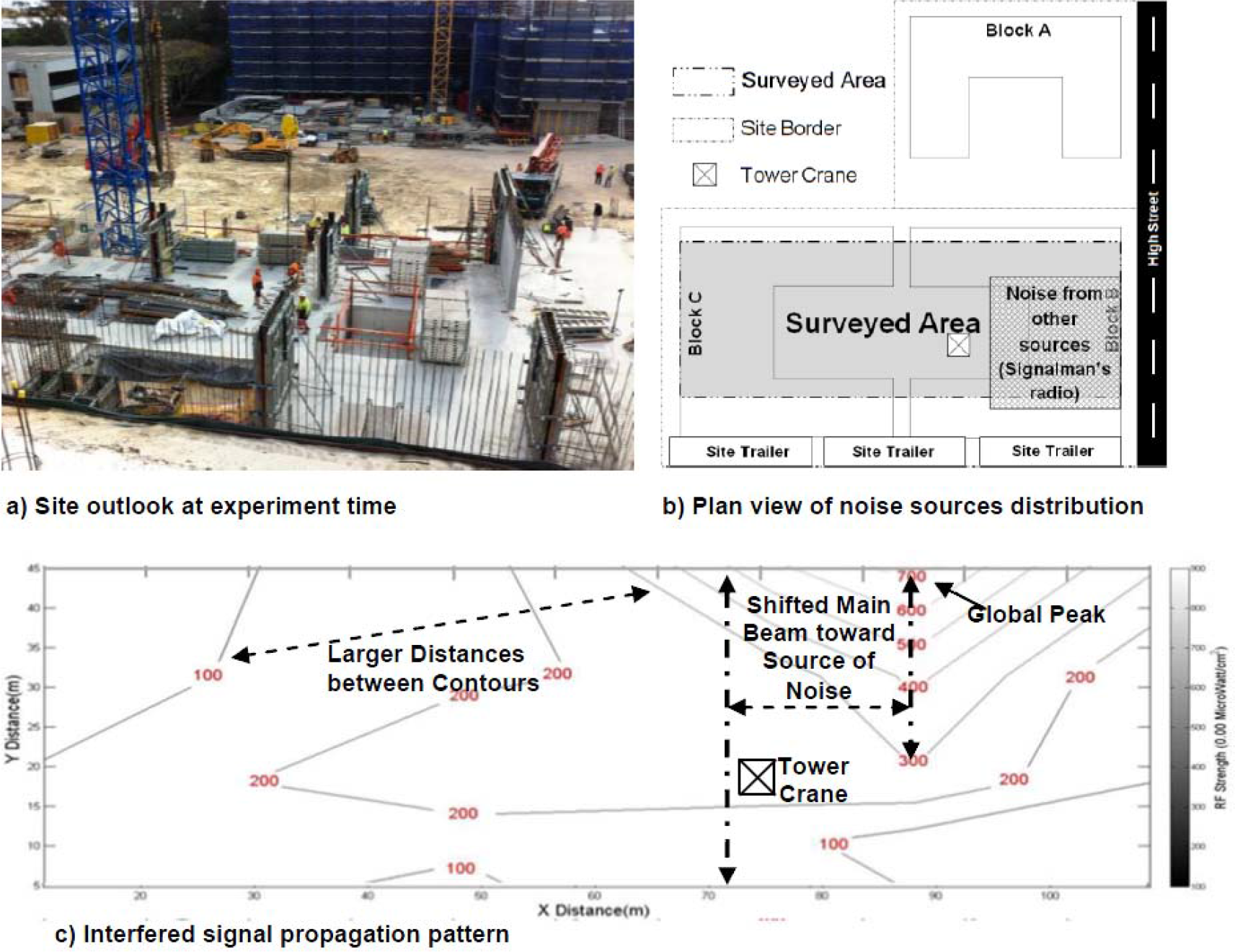
Inference from other emission sources caused a higher global peak, shifted the propagation main beam north, and generated greater distances between consecutive contours
4.1.4 Effect of Elevation on Signal Attenuation
Due to the architectural design, only lower levels and the ground floor have wide-open areas. Therefore, the impact of elevation on signal propagation patterns was analysed in two separate steps. Figure 10-a) depicts the surveyed area in each study. The principle difference between this study and existing indoor signal dissemination formulae is that measurement at each level is done when that level is the highest built floor and it resembles an open area but at various heights. It was observed that when a higher floor is completely built, the signal penetration at lower levels approaches zero. In other words, the construction of the roof and peripheral structural and parapet walls completely blocks signals. Therefore, additional access points have to be installed indoors to extend the network inside the building. Figure 10-b) shows the mean power density on each floor. It seems that downward transmission is more sensitive to the height difference between transmitter and receiver antennae than upward transmission. The interaction of signals with the Earth's surface in downward propagation causing an asymmetric propagation field and is the main reason for this inconsistency. However, for simplicity we assume symmetric propagation around antenna's main emission beam. The logarithmic attenuation of power as a function of the height difference between sender and receiver is agreed upon among scholars [35]. The logarithmic propagation model in the form of equation 5 was applied to find the antenna's height and mean intensity at the antenna's level:

Effect of height on signal attenuation

where P is the received power at elevation h and C is the power at antenna level e. Table 3 summarizes the procedure for finding the best-fit logarithmic function by changing e. Note that the first level data point is excluded because it was judged to be faulty data. So, the elevation loss based on effective height (h-e) is estimated using equation 6:
Predication of elevation loss parameters (R2 is the coefficient of determination of the regression)


where Lh stands for elevation loss. Comparing this study's results with an empirical but well-known expression from Bullington [36]:

As shown in Figure 11, the Bullington formula overestimates the deduction by a factor of 10. This is obviously initiated because this formula was developed for vehicular communication, which reemphasizes the necessity of developing construction-specific formulae. The Bullington formula is also not applicable to the calculation of close-to-surface planes (i.e., h<1m).

Comparison of the collected data with predictions using the Bullington formula
4.1.5 Effect of Construction Elements
Each construction method requires a specific setup of temporary structures. For example: a concrete deck requires a formwork on metal posts until it reaches a predefined strength. Scaffolding is necessary to provide access to the façade and outer boundary of a building and, furthermore, health and safety guidelines require extra instalment. This section will discuss the effect of safety nets shown in Figure 12. Signal strength data were collected after the safety screen and scaffold for a particular level were set-up. The data presented in Figure 10-c) verifies the expected drastic impact of the 6 m steel safety net in place over the scaffolding. The area surrounded by the safety screen and scaffold was surveyed and the results showed that total power decreased from 0.0012 (W) to 0.0008 (W) over the selected area.

Effect of scaffolding and a safety screen on blocking signal penetration
Overall, the monitoring of WiFi signal strengths during the construction of a multi-story building proved that not all construction activities affect signal propagation patterns in the same way. Understanding of each individual interaction is required to design and establish a reliable wireless network to support e-communication and control at the activity level.
5. Summary and Conclusion
The success of BIM proves that providing connectivity for the large amount of data needed in construction provides significant benefits to its participants. However, BIM has not been expanded to the work-front. Enabling the meeting of operational needs - such as just-in-time delivery - could be easily accomplished by the BIM-supported automated tracking of all resources. At the same time, BIM provides a useful framework to store as-built data. This paper presents a model to ally BIM with site-level information needs and data acquisition systems. Because this combination facilities real-time the communication of control data in a well-structured format, it supports the efficient control of construction activities.
Special attention has been paid to the issue of creating a secure and reliable wireless network enabling the integration of the work-front with a project network. A security framework was proposed to ensure uninterrupted information flow across an installed WiFi network. Field studies on an active construction site revealed that a dynamic site layout, operating machinery, interfering noise and elevation are important barriers to a pervasive network. The theoretical models predicted that, because of construction activities, site coverage patterns are subjected to change even within one working shift. This prediction was quantified by measuring the signal intensity over selected areas.
The collected data confirmed that existing practical models overestimate the attenuation of signal propagation at construction worksites. Excavation affects signal propagation patterns by blocking or developing the line of sight between router and user. It was observed that the geometry of deposited excavated soil influences the mean received signal power across the site. It was concluded that, in general, a higher deposit spread over a smaller area causes less attenuation than a lower but more widely spread deposit. However, the deposit must be at least as high as the router antenna to significantly reduce signal propagation. Particular attention should be paid in locating network antennae in order to establish multi-path links between emitters and a receiver. The redundant links are required to ensure a connection when mobile equipment temporarily blocks a direct line of sight. Also, elevation was recognized as an important factor affecting the network penetration rate. In this regard, power loss as a function of the absolute height difference between the antenna level and point of activity was derived, which is applicable in setting up a wireless network across a construction site. Network extenders are required to be embedded within the proximity of any scaffolding to compensate for the inevitable signal decay. However, powering the extenders forms a bottleneck when further extension is required at the construction site. Finally, signal enhancement is essential if SNR exceeds a threshold value, a topic that lies outside the scope of this paper.