
Abstract
A flexible robotic spine actuated by shape memory alloy (SMA) can achieve both bending motion and impact absorption, which will allow robots to realize a variety of postures. In this paper, the robotic spine is designed and simplified into a multi-segment dynamic model based on several verified assumptions. The SMA wire is modelled using the Seelecke-Muller-Acenbach theory. An iterative algorithm is developed to address the external forces distributed along the spine and compute the spine's bending angle. Based on the dynamic model, we improve the simulation structure and search algorithm to achieve good efficiency and stable solutions. Experiments are conducted to verify the simulation and the results fit the simulation prediction well, with error of less than five degrees. Design optimization with our simulation tool based on several parameters is also discussed in this paper.
Introduction
The spine is an important part of the anatomy of human beings and animals. With the development of humanoid and biomimetic robots, more and more researchers have focused on improving these robots by incorporating a spine. The effect of a flexible spine on energy efficiency and stability has been investigated [1]. Gait planning for robots with spine and related control methods have also been studied [2–3].
The spine has two main functions in robots. First, it increases the degree of freedom for dexterous movements and allows rapid leg locomotion. Second, a flexible spine can successfully absorb impacts to increase the efficiency and stability of the robot [4]. Some spine-robots have been developed and studied[1,5–6]. However, few of these designs include both the functions mentioned above. The humanoid robots “Kenta” and “Kotaro” developed at the University of Tokyo [7–8] were each given a spine with tendons, which was equipped with 40 motors and 62 tactile sensors. It was enormous, expensive and not feasible for small robots. The biomimetic robot “Robota” developed by A. G. Billard et al. [9–10] is equipped with a hydraulic spine that can absorb impacts, but it is highly complex.
The SMA is a smart material that is widely applied in different areas due to its high energy density and high strength [11]. The SMA spine has two advantages. First, it can achieve flexible movement and bending with shape recovery. With pseudo elasticity, SMA becomes a highly elastic beam when fully actuated, and is excellent for absorption. Second, the spine is highly compact for miniaturization and superior to spines actuated by motors and hydraulics in volume, weight and cost. There are numerous studies on fundamental SMA models and SMA applications [12–18]. Related control methods have also been studied [19–22]. In particular, M. Sreekumar modelled and studied the deflection of an elastic beam actuated by SMA wire [23]. G. Zhou set up an experiment to study the dynamic deflection [24]. The stress and deformation profile of such mechanisms have also been investigated in some studies about SMA actuators for biomimetic robots [25–26]. In [27], A. S. Veeramani studied the dynamic behaviour of an SMA-actuated catheter. But in this application, little force is applied on the catheter; thus, external force was not included in their model. It is different in the case of the robotic spine.
Based on these concepts, we describe a novel spine mechanism actuated by the shape memory alloy (SEA) and present a dynamic model that can deal with dynamic external forces and gravity distributed on the spine, as well as an iterative algorithm to calculate spine behaviour efficiently. We also present several experiments to analyse the influence of each parameter and optimize spine capacity.
This paper is organized as follows. Section 2 introduces the design principles and methods of the spine mechanism. In Section 3, we establish a dynamic model based on the design, which can deal with dynamic external forces distributed on the spine. An iterative algorithm is created to calculate the spine behaviour efficiently. Section 4 describes the simulation platform and its prediction is verified in Section 5, which presents the experiments to analyse several design parameters of the spine for capacity optimization purposes. Finally, Section 6 concludes the paper.
Design principles and methods
The robotic spine consists of a flexible tube, four SMA wires, nine rings to hold the wires along the tube, and two disks used to fasten the wire at each end. The flexible tube (460 mm length, 20 mm OD, 8 mm ID) is made of polyurethane (PU) which is notable for its outstanding tensile. The central hole of the tube is used to accommodate the electric wires connected to the SMA wires, otherwise they would hang down outside the spine, which might interfere the bending. The rings (20 mm ID for the 3 mm-thick middle plate, made of POM for insulation) are installed on the tube with set screws. The inner diameter of the shoulder is slightly larger than the tube, which leaves space for the tube to bend (about 45 deg) without introducing a significant increase of the tube's moment of inertia. Four pores are distributed symmetrically (14 mm in radius around the centre) on the ring to keep the SMA wires along the tube. Another four pores are for sensor use. Two disks (45 mm OD, POM) are covered on each end of the spine. Four SMA wires (Nitinol wire, 0.5 mm diameter, 384 K transformation temperature, produced by Baoji Hengsheng Non-Ferrous Metals Co., China) are pre-stretched (4.8%) and fixed on the disks by bolts. When energized, the SMA wire contracts and bends the flexible tube to one side. Such a spine can generate two-DOF movement. Two or more such mechanisms can be linked end-to-end if more DOFs are required. The spine mechanism is shown in Figure 1.

The mechanism of the robotic spine actuated by SMA wires
In addition to the spine, a pedestal was designed for the experiment and optimization, which is shown in Figure 2. The pedestal is a structure (insulating material) which is heavy enough to stably support the bending spine and prevent turnover. On the pedestal there are four tension devices which can be used to adjust the strain of the SMA wires. Four pulling-wire displacement sensors are also installed on the pedestal. These sensors are prepared for future study to measure the run-time length of the SMA wires and are not used in this research. During the experiments, the disk of the spine can be installed into the pedestal to erect the spine and the tension devices can adjust the SMA wire strain.

The spine pedestal built for experiments and optimization
The complete model of the SMA robotic spine includes four sub-models, SMA phase transformation, SMA energy balance, SMA constitutive relation and spine bending. The three models related with SMA are based on the Seelecke-Muller-Achenbach approach [13], which is accurate and effective for SMA wire modelling and computationally efficient.
SMA phase transformation
Shape memory alloy consists of crystals that have three phases, which are two variants of martensitic (M+), martensitic (M−), and austenitic (A). Crystals in different phases have different properties and the phase transformation process is determined by the strain and temperature of the material. Key in modelling SMA is to accurately describe the phase transformation process, which can be represented by a set of equations as below.

where, xM+, xM−, x A are the fractions of the three crystal phases, respectively. P ij denotes the transformation probability from phase i to phase j.
The four transformation probabilities are determined by the Helmholtz and Gibbs energy functions, which describe the potential energy of crystals in different conditions. The Helmholtz energy function [28] considers only the influence of temperature and is the piecewise function as follows:

where ψ is the potential energy, E M and E A are the elastic modulus of M± and A, ε is the strain of SMA, ε T is the maximum recoverable strain in the martensitic phases, T is the material temperature, ε M (T) and ε A (T) denote the strain boundaries between different phases and Δβ(T) is related to the minimum potential energy of the austenitic phase. The coefficients a, b, c can be deduced according to the C1 continuity conditions (first derivatives are continuous) of the function
Δβ(T) is linearly related with the temperature T [29] as

The coefficients Δu and Δη can also be deduced with the C1 continuity conditions:

The strain-stress relations of SMA martensite and austenite are [28]:
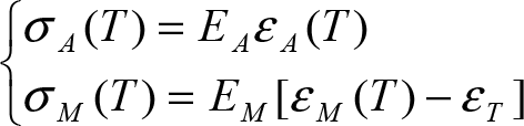
where σ A (T) and σ M (T) are the stress of austenitic and martensitic crystals, respectively. Numerous experiments show that the difference between σ A (T) and σ M (T) should be constant:

If the stresses of SMA under two different temperatures (T H and T L ) and the constant Δσ are known, Δu and Δη can be calculated according to Equations (5–7), which are expressed as follows:


Then, with Equations (5–9), ε M (T) and ε A (T) can be finally determined as:

where
Now the Helmholtz energy function is completely determined by known parameters. The Gibbs energy [13] takes the stress into consideration and is designated as:

where σ is the stress of SMA. The phase transformation probabilities are directly determined by this function, which is shown below:

where
V D is a parameter related to the volume of SMA crystal, τ is the resting time of SMA which can be tested by experiment, and k is the Boltzmann constant.
Now all the unknown coefficients of Equations (1) can be calculated, and the dynamic phase transformation process has been completely modelled.
As discussed above, the SMA phase transformation process is influenced by temperature. It can be described by the equation [28] as follows:

where ρ is the density of SMA material, c is the specific heat capacity, α is the heart transfer coefficient between the SMA surface and the atmosphere, S V is the surface area to volume ratio, (hM± − h A ) is the latent heat of phase transformation, and j(t) is the Joule heat per unit volume caused by the input current. Since the SMA wire is voltage controlled, j(t) is expressed as:

where V e and L are the voltage and length of the SMA wire, and ρ e (t) is the SMA resistivity, which is related to the phase fractions below:

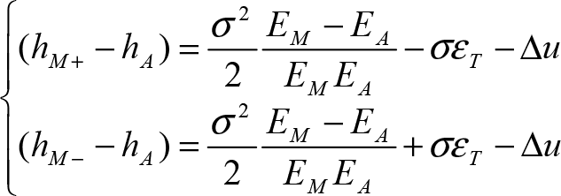
where λ A , λM+, λM− are the resistivity of the three types of SMA crystals. The latent heat (hM± − h A ) can be calculated with the equations below [17]:
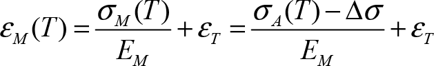
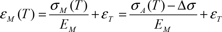
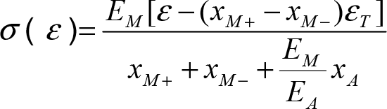
Given the three phase fractions, the relation between the stress and strain of SMA can be determined as [27]:
With the three sub-models just built, given the voltage input and stress variation in the SMA wires the dynamic behaviour of the SMA wires can be completely known. In this section, a spine bending model is created to describe the interaction between the SMA wires and the flexible tube. This model is used to efficiently compute the spine bending status if stresses in the SMA wires are given.
The spine bending model involves calculation of the deflection of a cantilever beam, which is a classic problem that has been studied by quite a few researchers. However, the common solutions are based on complex equations and related numerical calculations [30], which have low computation efficiency and cannot deal with complicated cases. In our model, the flexible spine is simplified into a segmented line and a segmented iterative algorithm is created which is able to calculate the spine deflection efficiently and flexibly, in order to deal with external forces and gravity. The simplification and modelling are conducted under several assumptions, which are separately verified, and the accuracy is proved to be within 2%.

Analysis of the bending moment caused by SMA wires in a single segment of spine
The maximum of Δx can be calculated geometrically:

where l s is the length of a spine segment. Therefore, the maximum deviation rate of the bending moment is
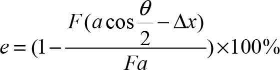
According to the design, a = 14mm, ls = 35mm. The bending angle of the spine is less than 40 degrees (tested by experiments); hence θ = 3deg. Using these data, the deviation rate e is calculated to be 1.7%. Therefore, it is safe to consider that the bending moment produced by SMA wires within each segment remains constant with the accuracy of 2%.
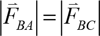
Figure 4 shows two spine segments and a relative force analysis. A is the disk, B and C are rings, T denotes the SMA wire pulling force on the disk, and FR is the force that acts on the SMA wire and is exerted by the pore on the ring. Because of friction, FR does not definitely point along the ring plane. If we take a short piece of SMA wire at the ring pore for analysis, since it is in balance

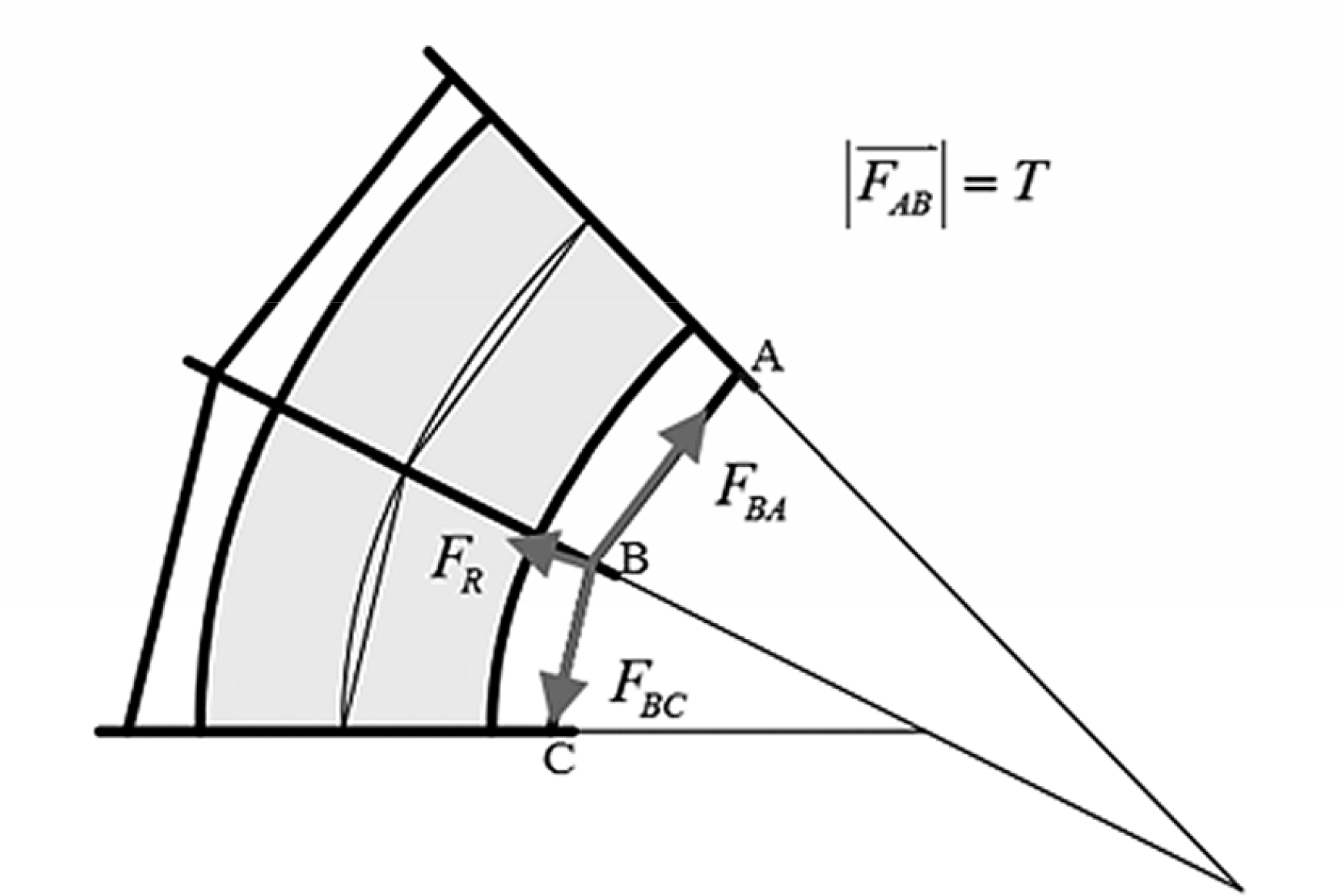
Analysis of the bending moment between two spine segments
The tensile force is constant along the SMA wire, so
According to Assumption Three, the bending moment in the first (counted from the disk A) segment (Segment AB) is constant:

The bending moment in the second segment (Segment BC) equals the moment caused by both the force
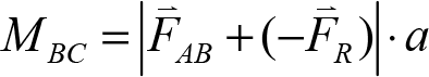
According to Equations (23–26):

Therefore, the bending moment caused by SMA wires and transmitted from the disk through each segment remains constant, equal to T · a.
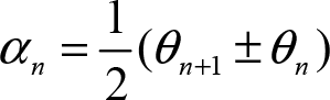
Under the four assumptions above, the robotic spine can be simplified into a segmented line model. Figure 5 shows that several segments of the spine are abstracted into line segments. The spine is vertically placed and the top segment is called Segment One. The vertexes of the segmented line corresponding to the centres of the rings. The angle relationships between the spine and its abstracted line model are shown below:


The segmented line model. Only three segments of the spine are shown
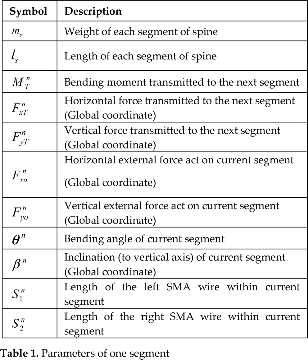
Using the segmented line model, the analysis and calculation of the spine can be effectively simplified to flexibly deal with external forces and gravity influence The computation is segment-based, which means that the segments will be calculated in sequence. Each segment influences the next one through the bending moment and force transmissions. The force transmission means that for each segment, an equivalent force will be created to deal with the influence of the external forces that act on its preceding segments. For computation, each spine segment owns a set of parameters. Table 1 lists the parameters owned by the nth segment.
Parameters of one segment
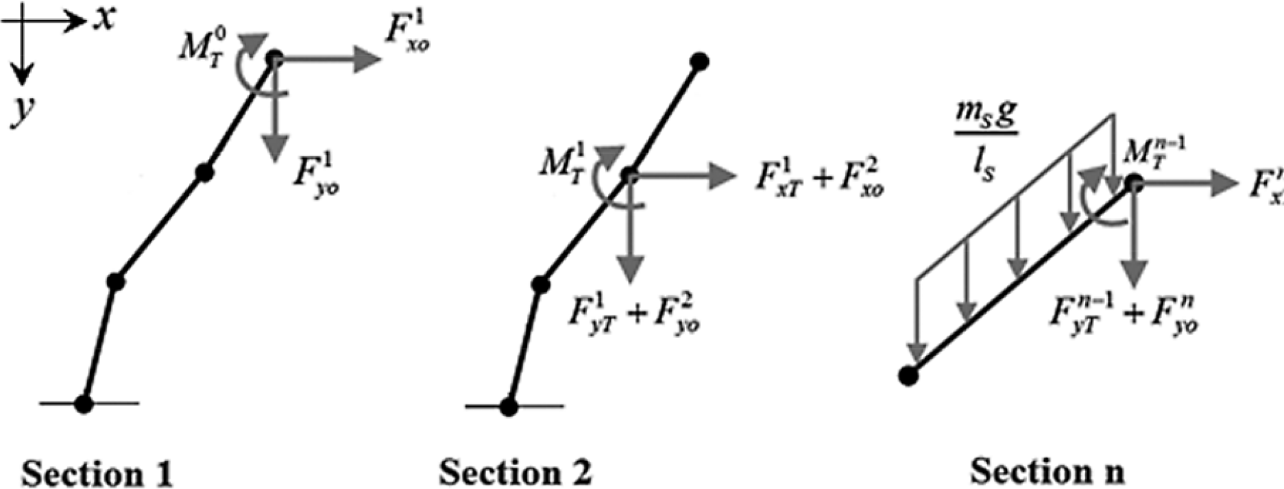
As shown in Figure 6, the force transmitted to the next segment is the total of the force transmitted from the previous segment; the external force acts on the current segment and its gravity, which is as follows:
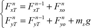
Bending moment and force transmission analysis for segment-based computation
The bending moment transmitted to the next segment includes the moment transmitted from the previous segment and the bending moment generated by the gravity and external forces of the current segment:

The initial bending moment for the first segment is generated directly by the pulling forces of SMA wires, expressed as:
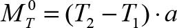
where T1 and T2 are the pulling forces of the left and right SMA wires. The basic equation for deflection calculation is:

where R is the bending radius, I is the section moment of inertia, and E is the elastic modulus. According to this equation and the analysis in Figure 6, the bending angle of the nth spine segment can be calculated thus:

When the bending angles of all the segments are known, the total length of the SMA wires can be calculated geometrically:

The inclination of each segment is determined by its bending angle and the inclination of the next segment (beneath):

All the equations for bending status calculation have been given above. However, according to Equations (33) and (36), the bending angle of each segment is related to the previous segment while the inclination calculation depends on the next one, so it is impossible to compute the segments in sequence. An iterative algorithm is created to solve this problem. In the first round of calculations, all the segments' bending angles and inclinations are zero initialized; thus the calculations can be successfully conducted based on these initial values. New results of the bending angles and inclinations will be used in the next round of calculations. Such a process is iterated until the difference in calculation results (the bending angle) between current and previous rounds, which is regarded as the computational error, is small enough.
Table 2 shows the numbers of iterations under different error requirements, proving the effectiveness of our iterative algorithm.
Computational efficiency of the iterative algorithm

Block diagram structure
MATLAB Simulink is used for the simulation. The design of the block diagram and the compute algorithm are important in terms of simulation efficiency and stability. For the block diagrams used in [27,31] for SMA-actuated mechanism, the SMA constitutive relation and the spine bending model were computed in two separate block modules (shown in Figure 7), causing an algebraic loop (feedback loop). Such an algebraic loop impairs the stability of the solution. In [27], the block diagram structure worked without problem because the mechanism is actuated by only one SMA wire. However, in our design, the spine is actuated by two antagonizing SMAs, and hence the output strain of the spine bending model becomes much more sensitive to its input stress, which makes the solution easier to diverge. Using this diagram structure, the simulation fails when the elastic modulus of the flexible tube is less than 500 MPa.

The block diagram of the robotic spine model (without improvement)
To solve this problem, we improve the block diagram by combining the SMA constitutive relation and the spine bending model into a single module (shown in Figure 8) so as to eliminate the algebraic loop. Inside the composite module, an effective algorithm is used to calculate the stresses and strains of the two SMA wires and the bending angles based on the only input of the phase transformation fractions, which makes the block diagram structure more compact and stable.

The block diagram of the robotic spine model (with improvement)
While the block diagram structure influences the stability of the simulation, the search algorithm in the composite module is critical for the simulation efficiency. The algorithm has been improved several times and the final version is described below:
Search Target: Given the phase fractions input, a search is carried out for a solution of the strain in the left SMA wire that satisfies the error requirement. The strain in the right SMA wire, the stresses and bending angle can then be calculated from the search result.
Initial Search Range: The strain (left SMA wire) at the last time-step is denoted by ε[t − 1]. Assuming the strain is fixed (ε[t − 1] = ε[t]), with the change of the phase fractions from time [t−1] to [t] the stress will change according to the SMA constitutive relation and pull the flexible spine from its last bending position θ [t − 1] to the new position θ[t]. In this position, the corresponding strain becomes ε[t] (using equation (35) to calculate), which is not consistent with ε[t−1] in the assumption. According to the SMA constitutive relation, a change in strain always suppresses the change in stress, so the spine cannot bend all the way to θ[t], which means that the actual bending position is between θ[t] and θ[t−1], and the actual strain is between ε[t−1] and ε[t]. Therefore, ε[t−1] and ε[t] are used for the initial search range.
Search method: In each loop iteration, the search range is narrowed by half. The midpoint of the previous search range is used to calculate the corresponding new θ and ε. These are compared with the midpoint so as to determine the new search range. The search method is described in Figure 9.
Search Accuracy: The loop is iterated until the search range is small enough. The length of the final range is the error of the algorithm.

Flow chart of the search algorithm
Table 3 shows the efficiency of different search algorithms that have been tried. The running time is for the entire simulation process of the robotic spine. The simulation time length and simulation step are set as 20 s and 0.01 s. As shown by Table 3, by improving the algorithm, the computation of a 20 s dynamic simulation can be finished within only one minute.
Efficiency of different search algorithms

Experiment setup
A CompactRIO controller (National Instruments, cROP-9074) was used in the experiment to control the robotic spine. A Labview GUI was built for interaction. A digital output module (NI 9472) was installed on the controller to generate digital signals and to energize the SMA wires with an amplifier. Two DC power sources (PS-305D) provided power for the controller and the amplifier separately. A digital camera was used to acquire the bending status of the spine every 0.5 s, and then the bending angles in the photos were measured using MATLAB. The experiment setup is shown in Figure 10.

The robotic spine experiment setup
In our design, the pre-strain of the two SMA wires are both 0.048. According to Equation (19), the corresponding phase fractions xM+, xM−, x A are 0.9528, 0.0472 and 0, respectively, which are the initial values for simulation. The other parameters used in the simulation are shown in Table 4.

Two experiments were conducted and compared with the simulation predictions. The first experiment is used to study the hysteresis of the robotic spine. The second experiment is used to study the dynamic behaviour of the robotic spine when the two SMA wires are actuated alternately.
In the first experiment, the right SMA wire was actuated with step voltage input (3.2 V). After 20 s, the input was stopped and 30 s were allowed to pass. As shown in Figure 11 and Figure 12, the simulation prediction fairly accurately fits the experiment results, with a maximum error of 3.57 degrees. The hysteresis is accurately described with static error below one degree.

Comparison between simulation prediction and experiment results (hysteresis)

Prediction error (hysteresis)
In the second experiment, the right SMA wire was actuated with step voltage input (3.2 V) first. After 20 s the input was changed to the left SMA wire and 20 s were allowed to pass. As shown in Figure 13 and Figure 14, the variation trend of the spine bending angle is consistently described by the simulation prediction, with maximum error of 4.94 degrees. Large errors (above 2 degrees) occur always when quick movement happens and last for only a short time (about 2 s).
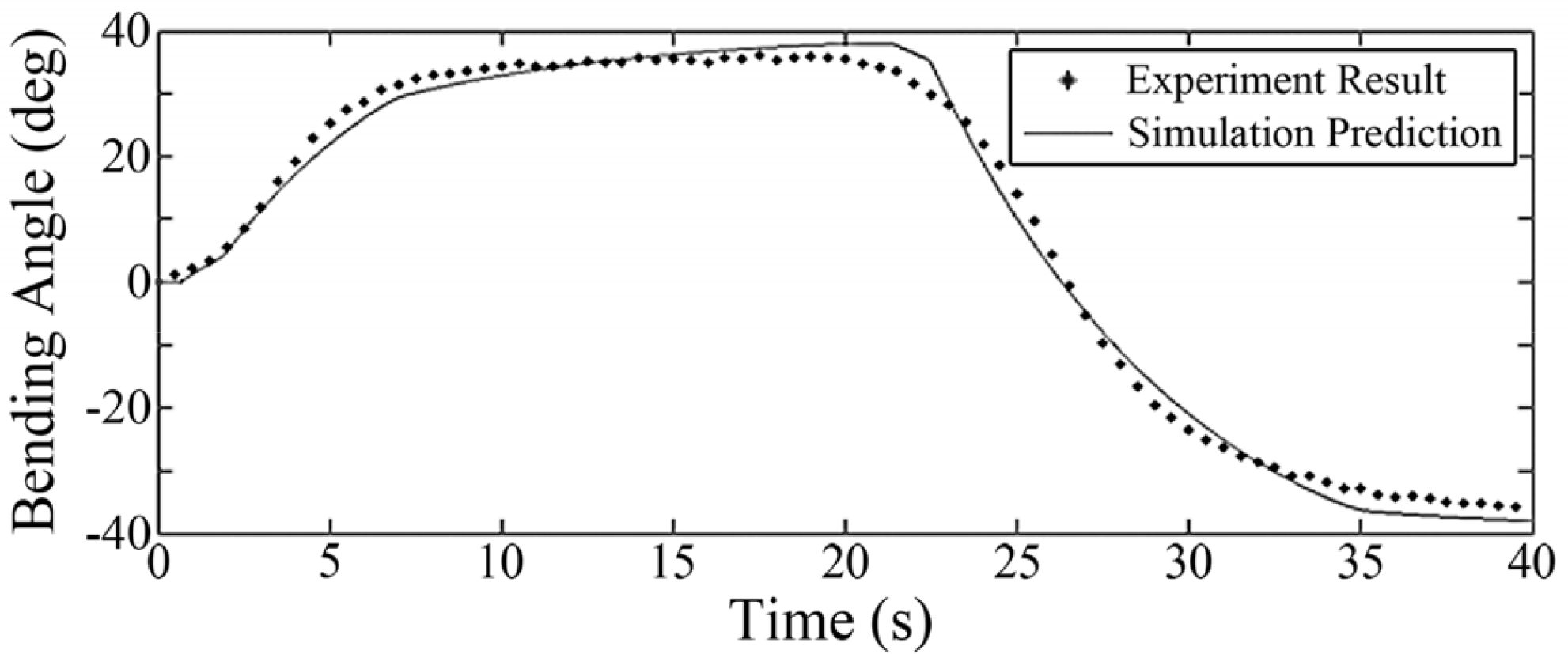
Comparison between simulation prediction and experiment results (altemate drive)

Prediction error (altemate drive)
In conclusion, our simulation platform can effectively describe the hysteresis and dynamic behaviour of the robotic spine. The prediction errors are limited within 5 degrees and below 3 degrees for most of the time. Despite the errors, maximum bending angles and responding speed are accurately reflected.
The experiment results show the effectiveness of our simulation methods. However, the simulation depends on plenty of parameters which cannot all be determined without any deviation, and it is impossible for any simulation result to be exactly consistent with the experiment. Actually, it is more accurate for simulations to show the relations between different parameters, which focus on variation trends rather than exact values, and hence are influenced less by the parameter errors. In our research, several sets of simulation experiments are conducted to study the influence of several parameters on the capacity of the robotic spine.
The capacity of the robotic spine is reflected by three parameters – maximum bending angle, responding time and actuating ability. In each experiment, the left SMA wire is given a step voltage input. The stable angle is defined as the maximum bending angle. The input is then switched from the left SMA wire to the right one. The time it takes for the spine to bend to 90% of the stable angle is defined as the responding time. After that, a 1 N force is exerted vertically (global coordinate) on the top disk of the spine and until stable; the reciprocal of the bending angle change is defined as the actuating ability, which indicates the resistibility to external forces.
In the first set of experiments, the parameter a (distance between ring pore and ring centre) was changed in each simulation. For the second set, the controlled variable is the number of SMA wires on each side of the flexible tube. The experiment results are shown in Figure 15 and Figure 16.

Simulation experiments with the variation of a

Simulation experiments with the variation of the numbers of SMA wires
Two useful conclusions can be drawn from the experiment results. First, placing the ring pore closer (no less than 6 mm) to the ring centre (thus reducing a, which means the SMA wire is closer to the central axis of the flexible tube) when designing can enhance the maximum bending angle effectively without decreasing the responding speed. Second, increasing the number of SMA wires on each side of the spine can improve the actuating ability and bending capacity at the expense of a slight change in response speed, which means that it is possible to apply the spine in larger robots.
In this paper, we have presented the design of a flexible robotic spine actuated by SMA wires, which can generate bending movement and absorb impacts. The mechanism is highly compact, low cost and easy to miniaturize. In a prototype the bending angle could reach about 35 degrees in the experiment without any optimization, proving the feasibility of the design.
A computationally efficient model of our design was created to describe dynamic behaviour that can deal with the influence of gravity and external forces. A simulation platform with a related algorithm was able to achieve stable results with parameters configured in a wide range of values, and a 20 s simulation was able to be run within one minute.
Experiments were conducted to verify our model and simulation methods. The experiment results were w consistent with the simulation prediction. Several sets of simulations were performed to study the influence of two design parameters on the robotic spine capacity. Comparatively small distance (no less than 6 mm) between SMA wire and central axis of the flexible tube (a) is beneficial for the maximum bending angle, while more SMA wires on each side of the spine can enhance the resistibility to external forces. Both of these parameters have little influence on the response speed.
In future work, a series of robotic spine with different a and numbers of SMA wires will be built and experiments carried out. The results will be compared with the simulation experiments in this paper so as to further verify our model and simulation methods. For optimization of the robotic spine, more simulation experiments will be conducted to study parameters such as pre-strain of SMA wires and elastic modulus of the flexible tube.
Footnotes
7.
This work was supported by the National Nature Science Foundation of China (Grants NO. NSFC: 61075078), the Natural Science Foundation of Zhejiang Province (Grant No. LQ12F03009) and Fundamental Research Funds for the Central Universities (Grants No. 2012FZA5014).