
Abstract
This work presents the implementation of a 3D reconstruction system capable of reconstructing a 360-degree scene with a single acquisition using a projection of patterns. The system is formed by two modules: the first module is a CCD camera with a parabolic mirror that allows the acquisition of catadioptric images. The second module consists of a light projector and a parabolic mirror that is used to generate the pattern projections over the object that will be reconstructed. The projection system has a 360-degree field of view and both modules were calibrated to obtain the extrinsic parameters. To validate the functionality of the system, we performed 3D reconstructions of three objects, and show the reconstruction error analysis.
Introduction
In recent times, 3D reconstruction systems have become fundamental for object modelling applications such as virtual environments development for archaeology [1, 2], video surveillance [3, 4], quality control processes [5, 6], disease diagnosis [7, 8], and measurement [9, 10].
The 3D reconstruction systems that incorporate lenses and mirrors into acquired images with an omnidirectional field of view are called catadioptric systems. A common approach for 3D reconstruction is the use of structured light projection with a 360-degree laser line combined with omnidirectional stereo cameras that take images with multiple views [11, 12]. The disadvantage of these approaches is that we can only recover 3D information in the area of the laser incidence, limiting the reconstruction area. Another approach is the use of an omnidirectional camera constructed by a traditional perspective camera and a pyramid reflector [13].
In [14], the authors propose a panoramic sensor using a convex mirror capable of producing panoramic depth maps by feature matching from two panoramic images. However, this technique fails with textureless surfaces, being unable to match the texture features. A stereo system with a texture projector can eliminate or reduce error matching. For this reason we propose a new 3D reconstruction system based on a projection system and a single catadioptric camera.
In order to obtain a good reconstruction, it is necessary to calibrate the catadioptric cameras, estimating the geometric model of the camera. In recent decades, several algorithms have been proposed for the calibration of omnidirectional cameras [14–18].
The 3D reconstruction systems based on conventional cameras have been well-studied [19–22]. However, for applications where we need to process a 360-degree field of view (for example inside hollow objects), conventional systems implement a piecemeal reconstruction. In this paper, we describe the 360-degree 3D reconstruction of a scene from a single acquisition using a projection of patterns.
Geometrical model of the catadioptric vision system
Experimental setup
Figure 1 shows a schematic overview of the experimental setup for the proposed panoramic 3D reconstruction system, which consists of two parabolic mirrors, a Marlin F-080 CCD camera, a composite lens (L), and a Sony VPL-ES5 3LCD light projector.

Schematic drawing of the experimental setup for the proposed panoramic 3D reconstruction system.
First, a catadioptric camera was assembled, aligning the mirror (PM1) with the CCD camera in order to capture the full environment that is projected onto the mirror. Using a chessboard calibration pattern, we calibrate the catadioptric camera obtaining the intrinsic and extrinsic parameters. Once the camera is calibrated, we design the optical setup of the pattern projection system, placing the mirrors (PM1, PM2) back-to-back. In front of the projector, a composite lens (L) was inserted in order to reduce the projected image towards the mirror (PM2), as seen in Figure 2.

Experimental setup for the panoramic 3D reconstruction system. The system consists of a Marlin F-080 CCD camera, two parabolic mirrors (PM1 and PM2) on a back-to-back configuration, and a Sony VPL-ES5 3LCD light Projector with a composite lens (L).
We focused our work on two areas: calibration and 3D reconstruction. For calibration, we used a plane with a printed calibration pattern and a second calibration pattern projected by the PM2-projector system. The printed pattern was used to calibrate the camera-PM1 system, while the projected pattern was used to calibrate the PM2-projector, and to calculate the rotation and translation matrix between the PM1 and PM2 mirrors. For reconstruction, we performed matching between the projected image and the acquired image. For matching, we used the epipolar curves constraints. Finally, we use three objects to evaluate the reconstruction system: two perpendicular planes, a cylinder, and a semi-sphere.
In order to calibrate the catadioptric camera, we use the geometric model proposed in [18]. To solve this model, we use a chessboard pattern to obtain the intrinsic parameters: mirror curvature and image centre, as well as the extrinsic parameters: rotation and translation between the camera reference system and the pattern.
The general model for the catadioptric camera has two reference systems: the camera image plane, represented by (
An imaging function g relates a point


General model for the catadioptric camera. A point
where

The function f depends on

where
Thus, eq. (1) can be rewritten as eq. (4).

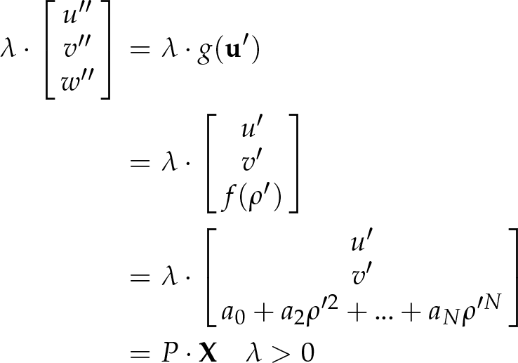
For cameras with parabolic mirrors we use eq. (5) as proposed in [25]. This simplification allows us to assume a1 = 0, and rewriting eq. (3) we obtain eq. (6).

From the camera's calibration process, the parameters [A,
According to this, we assume that A = I, and
where
To perform the calibration, we used a printed chessboard pattern in different positions, which relates the camera's coordinate system with the world W through a rotation matrix RW→PM1 and a translation vector


Calibration pattern flatness (in mm) obtained using the Mitutoyo BJ1015 Coordinate measuring machine. This calibration pattern was used to calibrate the catadioptric camera (CCD-PM1) and the projection system (PM2).
For the calibration process, we obtain the extrinsic parameters for each image that indicate the position of the calibration pattern with respect to the camera reference system.
To eliminate the depth scale dependency λ
ij
, both sides of eq. (8) are multiplied vectorially by

From eq. (9), for each point

where x j , y j and z j and u j , v j are known, and correspond to the mirror points and image points, respectively. q1, q2 and q3 are given by:

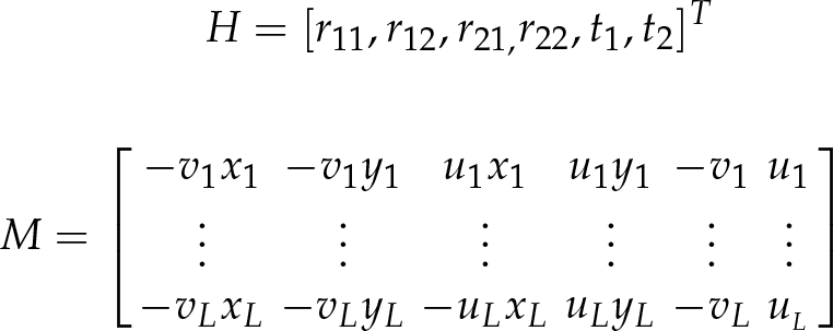
Eq. (10.3) is linear and has the unknown parameters r11, r12, r21, r22, t1, t2. Rewriting eq. (10.3) for L points of the calibration pattern as a system of linear equations, we get eq. (11).

where:
Using singular value decomposition (SVD), we can represent M = UΣV
T
, the solution to the system can be found in the singular vector
Once eq. (10.3) is solved to find the camera extrinsic parameters, we substitute the estimated values into the equations (10.1) and (10.2), and solve for the camera intrinsic parameters a0,a2, …, a N that describe the shape of the imaging function g.
Equations (10.1) and (10.2) are rewritten again as a linear system of equations. But now, we incorporate all the k calibration pattern observations to obtain eq. (13).
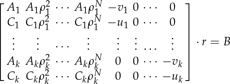
where:

The solution of the system is obtained using the pseudoinverse matrix. Thus, the intrinsic parameters a0,a2, …, a N which describe the model, are now known. In order to compute the polynomial degree N, we actually start from N=2, then we increase N by unitary steps and we compute the average value of the reprojection error of all calibration points. The procedure stops when the minimum error is found.
In order to calibrate the catadioptric camera with the projection system (see Figure 6), we develop the following procedure:
A calibration pattern image was projected (see Figure 5a)) in different positions over the mirror PM2. The mirror PM2 reflects the image until the calibration plane W is found. The calibration plane position is known with respect to PM1, (as seen in Figure 5b)) because the calibration plane contains the printed pattern used to calibrate the camera-PM1 system. Once a catadioptric image is acquired by the camera-PM1, a subpixel algorithm provides the points of the projected calibration pattern. These points are represented as

a) Projected calibration pattern, b) Image captured by the catadioptric camera showing two calibration patterns in a white plane: the printed pattern is used to calibrate the catadioptric camera (camera CCD-PM1 mirror), and the projected pattern is used to calibrate the projection system (PM2 mirror-projector).

Schematic diagram of the panoramic 3D reconstruction system. The projections of 3D points
The plane where the projection pattern is located is defined by

where RW→PM1 and
The points

When the points
This function represented by g2 has known input parameters such as: the points
The

Epipolar geometry describes the relationship between positions of corresponding points in a pair of images acquired by central catadioptric cameras [14, 25], as seen in Figure 7. In this section, the alignment parameters (rotation and translation) between the camera-mirror (PM1) and the mirror(PM2)-projector are described.
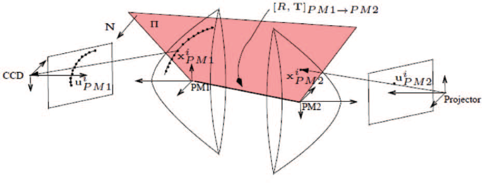
Epipolar geometry between two catadioptric cameras with a parabolic mirror. RPM1→PM2 is the rotation matrix and TPM1→PM2 the translation vector between both mirrors (PM1–PM2). ∏ is the epipolar plane.
The projections of 3D points

where × denotes the cross product. Simplifying the coplanarity constraint described in eq. (17), we obtain eq. (18):

where:

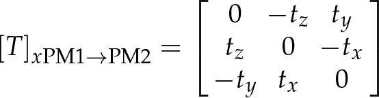
E is the essential matrix and [T]xPM1→PM2 is the antisymmetric matrix given by eq. (20):
To each point

In a general case, the matrix A2(E,
The vector

The normal vector n1 can be expressed in the projector's coordinates system using the essential matrix resulting in eq. (23):
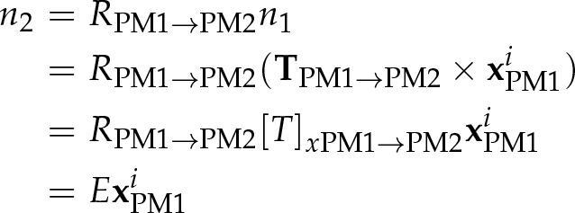
Thus, eq. (23) is denoted by eq. (24) as:
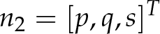
we can write the equation of the plane ∏ in the projector's coordinate system resulting in eq. (25):

The derivation of A2(E,

where b2 is the mirror parameter and p, q, s are defined by eq. (24).
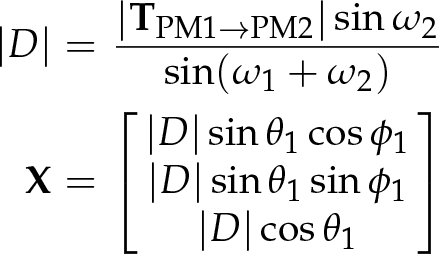
Knowing the rotation RPM1→PM2 and translation TPM1→PM2 between both mirrors, we can find the relationship between the pixel coordinates in the image and the angles defined in the parabolic mirror reference system (see Figure 8). Having this information, 3D point coordinates are calculated from the correspondence of points in the projected image and the acquired image by the catadioptric camera [14].

ω1 and ω2 are the angles between the points
Given two points

From the distance |D| between two points
Calibration
We used 26 images to calibrate the catadioptric camera, some of these are shown in Figure 9. As we can see, the white plane (

Calibration images. Twenty-six images were used to calibrate the catadioptric camera. Each image contains a white plane with the two calibration patterns in different positions and orientations.
The printed pattern is used to calibrate the catadioptric camera formed by the CCD camera and the PM1 mirror, and to compute the plane
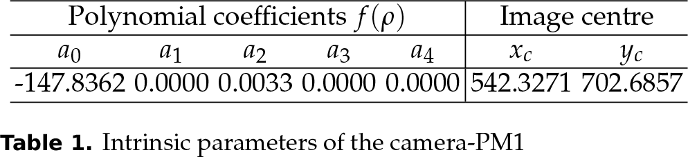
The intrinsic parameters from the catadioptric camera are presented in Table 1. The values of the mirror's curvature allow us to confirm that it is a parabola.
Intrinsic parameters of the camera-PM1
The intrinsic parameters obtained for the PM2-projector system are presented in Table 2.
Intrinsic parameters of the PM2-projector

The rotation and translation matrix between the mirror PM1 and the mirror PM2 as described in section 2.4, correspond to the values shown in eq. (29).

When building the optical setup for the panoramic 3D reconstruction system, we carefully aligned the PM1 and PM2 mirrors. However, as can be seen in the rotation matrix R, a small misalignment exists.
To calculate the calibration error in the camera-mirror PM1 system, we considered the position of the 3D points on the printed calibration pattern in the catadioptric image. With the rotation and translation parameters, these points are projected towards the PM1 mirror, using the intrinsic parameters (shown in Table 1) that are mapped to the image. This way, we compared the points from the printed pattern projected to the catadioptric image with the points extracted from the acquired image by the camera.
The calibration error in the catadioptric projection system (PM2-projector) is obtained as follows: we extract the positions of the 3D points from the projected calibration pattern in the catadioptric image, and then these points are projected towards the mirror PM1 and are represented in the plane
The calibration error from the catadioptric camera (camera-PM1) is about 0.4 pixels, and the calibration error from the catadioptric projection system (PM2-proyector) is 1.56 pixels.
Figure 10 shows the direction of

where

Real dimensions of the experimental setup. L1, F1, L2 and F2 are shown at a larger size for visualization purposes. L1, F1, L2 and F2 are the sensor size, camera focus, display size and projector focus, respectively.
There are two solutions for
The normal unit vector of the mirror in (Z1,

where:
Considering that the angle formed by

Approximating RPM1→PM2 = I, we have the eq. (33):

where:

The angle of view θ of the reconstruction system is given by:
Substituting the values of the camera, projector and the mirrors PM1 and PM2, we obtain θ = 125.4125 degrees.
In order to test the functionality of the system, we reconstruct the object shown in Figure 11 containing two perpendicular planes.
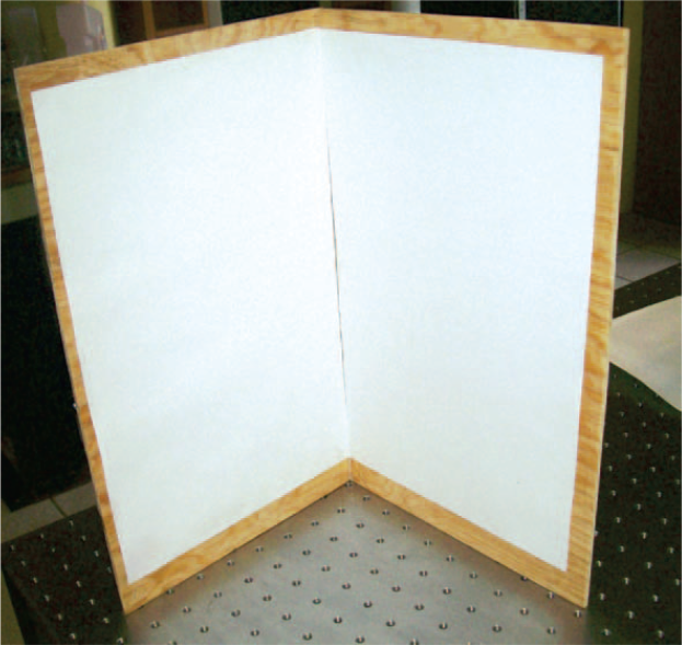
Test object 1: Perpendicular planes. A set of two perpendicular planes was used to test the functionality of the system.
The perpendicularity of the two planes was measured using the Mitutoyo BJ1015 Coordinate-measuring machine and Metrolog XG® software (see Figure 12) obtaining an angle of 89.192 degrees between them.

Measuring perpendicularity of the two planes using the Mitutoyo BJ1015 Coordinate-measuring machine.
To perform the reconstruction, we projected a pattern of points onto the perpendicular planes (see Figure 13), and then we acquired an image from this projection using the catadioptric camera (see Figure 14). The projected pattern points have random colours. We perform the correspondence between the acquired image and the projected image using the colour of the projected points and the epipolar curves constraints (described in section 2.4).
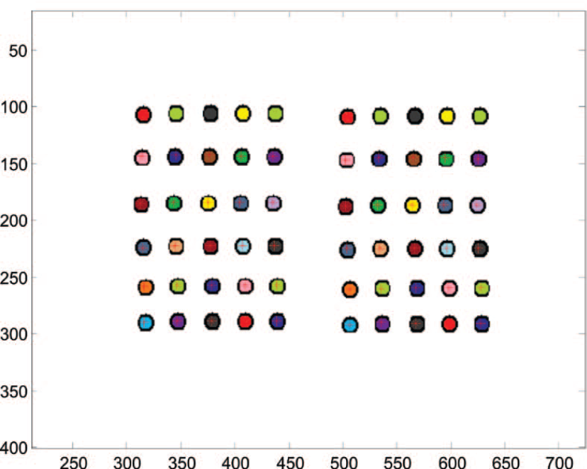
Projected pattern. The pattern projected by the PM2-projector system over the perpendicular planes consists of a set of points with random colours.
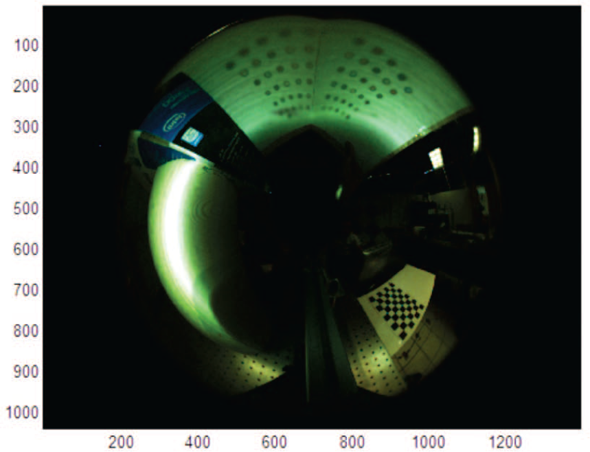
Catadioptric image with the points projected on the perpendicular planes, captured by the camera CCD-mirror PM1.
Epipolar geometry from the 3D reconstruction system is shown in Figure 15. Here we can see that the conic lines obtained with eq. (26) intersect in the epipole and passed through the corresponding points. Once the correspondence is found, we build the 3D reconstruction of the object. The reconstructed planes can be seen in Figure 16.

Epipolar geometry. Coloured projected points with their corresponding conics (epipolar lines).

3D reconstruction of the perpendicular planes.
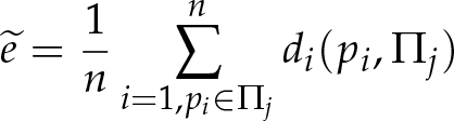
Having previous knowledge about the object formed by the two planes, we segmented the reconstructed points in the objects. Each object corresponds to one of the two perpendicular planes ∏1 and ∏2. Then, we calculate the error, considering the perpendicular distance di between the points and the corresponding plane using eq. (34).
In Figure 17, the perpendicular distance in millimetres from each point with the corresponding plane is shown. The graph shows a mean error of 2.4 mm on plane 1 and 3.6 mm on plane 2. The angle between the two planes is 89.8488 degrees.

Reconstruction error in perpendicular planes. Perpendicular distance error in millimetres of the points in plane one (red) and plane two (blue).
We performed two additional reconstructions test using a cylindrical object (see Figure 18) and a semi-sphere (see Figure 19).
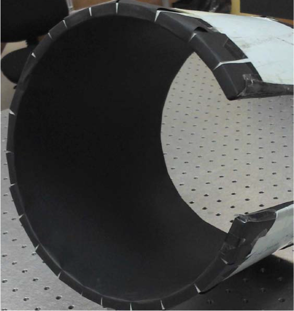
Test object 2: Cylindrical object. A section of a plastic tube was used to test the functionality of the system with curved-shape objects.

Test object 3: A semi-sphere was used to test the functionality of the system.
A pattern of points with random colours was projected inside the cylinder to obtain the results shown in Figure 20.

3D reconstruction of the plastic tube.
In order to know the real values of the cylinder, we perform a curve fitting with the 3D reconstructed points using Metrolog XG® software. The results indicate an error of 4.7657 mm (see Table 3) with respect to the real object radius.
Curve fitting results of reconstructed 3D points using Metrolog XG® software

The reconstruction of the semi-sphere shown in Figure 21.

3D reconstruction of the semi-sphere.
The panoramic 3D reconstruction systems found in the literature are based on two catadioptric cameras. Thus, the 3D reconstruction is based on the matching of corresponding points between two views. However, these methods fail in applications with textureless objects. In this work, we proposed a new reconstruction system based on a single catadioptric camera and a catadioptric projection system. The reconstruction can be done with a single acquisition or with multiple acquisitions moving the position of the projected points. For this, we first calibrate the catadioptric vision system, and then we calibrate the catadioptric projector. The reconstruction error in an object composed by two perpendicular planes was 2.4 mm on the first plane, and 3.6 mm on the second plane, with an angle of 89.8488 degrees between planes. The reconstruction error in the cylindrical object was 4.7 mm. Our future work will focus on obtaining denser 3D reconstructions and characterization of reconstruction uncertainty. Moreover, increasing the reconstruction area by moving the system inside the object.
Footnotes
5.
The authors wish to acknowledge the financial support for this work by the Consejo Nacional de Ciencia y Tecnología (CONACYT) through project SEP-2005-O1-51004/25293 and the financial support scholarship number 256319, and by the Instituto Politécnico Nacional through project SIP-20130165.