Abstract
There are more and more buildings with complicated shape emerging all over the world. Their walls require constant cleaning which is difficult to realize. In this paper, based on analyzing the characteristics of the working target, a new kind of auto-climbing robot is proposed, which is used for cleaning the spherical surface of the National GrandTheatre in China. The robots' mechanism and unique aspects are presented in detail. A distributed controller based onCAN bus is designed to meet the requirements of controlling the robot. The control system is divided into 6 parts, fiveCAN bus control nodes and a remote controller, which are designed and established based mainly on the P80C592. Finally, the motion function is described in detail. The experimental results confirm the principle described above andthe robot's ability to work on the spherical surface.
1. Introduction
At present a large number of high-rise buildings with curtain glass walls are emerging in modern cities. External cladding of buildings not only provides an attractive exterior appearance but also increases their durability (Zhang, H. et al., 2004). Because of the current lack of uniform building structures, wall cleaning and maintenance of high-rise buildings is becoming one of the most appropriate fields for robotization. The development of walking and climbing robots offers a novel alternative solution to the above-mentioned problems. Several different prototypes were designed for this type of application during the last two decades (Briones, L. et al., 1994), (Luk, B.L. et al., 2001), (Liu, S. et al., 2000). Development and application of cleaning robotic system can free workers from the hazardous work and realize the automatic cleaning of high-rise buildings, furthermore improve the technological level in building maintenance.
At the moment the number of buildings with complicated shape is increasing worldwide. Cleaning the outer surface of these kinds of buildings is always dangerous and laborious work in mid-air. Since 1996 the group at the Robotics Institute of BeiHang University has been developing a family of autonomous sky cleaner climbing robots with sliding frames for glass-wall cleaning. The first model (Wang, W. et al., 2001) has only limited dexterity and cannot work on a vertical wall. Because it has no waist joint, the robot is unable to correct the direction of its motion. The frequency for dealing with and crossing obstacles is very high and the cleaning efficiency is only about 300 m2/8 hours. The second robot (Zhang, H. et al., 2004) is very portable and the cleaning efficiency is about 600 m2/8 hours. But as considerable stress was laid on weight reduction, the construction stiffness is somewhat so that there is a small distortion while cleaning and climbing.
SIRIUSc (Elkmann, N. et al., 2002) is a walking robot for the automatic cleaning of tall buildings and skyscrapers. The robot can be used on the majority of vertical and steeply inclined structure surfaces and facades. However it has to be positioned sideways by the trolley on the top of the roof as it cannot move sideways automatically. The other kind of robot was developed for the Leipzig Trade Fair in 1997 (Elkmann, N. et al., 2002). It is the first facade cleaning robot for vaulted buildings worldwide. Because of the building's unique architecture, the robot is a very specialized system and is not modularly-designed. Although some robots have been developed for wall cleaning, most of them can only deal with planes with inerratic shape.
In this paper a new kind of auto-climbing robot is proposed, which is used for cleaning the spherical surface of the National Grand Theatre in China. The experimental results confirm the principle described and the robot's ability to work on the spherical surface.
2. Overview of the robot
2.1. Cleaning Target
An auto-climbing robot for cleaning glass walls with a complicated curved surface was developed in 2002 (Liu, R. et al., 2003). Taking the National Grand Theater of China as the operation target, the robot can autonomously climb and clean its covering outer walls with the shape of a half-ellipsoid. The height of the theater top is 54 m from the ground, and the long axis and short axis of the ellipse on the ground are 212 m and 146 m respectively, as shown in Fig. 1. The total area of outer walls is 36,000m2, with 6,000 m2 of transparent glass walls, and 30,000 m2 of Titanium walls. The surface walls consist of more than 20,000 glass and titanium planks. In order to achieve a half-ellipsoid, each plank is constructed at a different size and is connected to its surrounding planks at an angle. There are altogether 54 layers on the wall, with each layer having a different height and sloping angle. A circling track around the half-ellipsoid which was originally designed for the needs of construction and maintenance is mounted between every two layers.

National Grand Theater of China
2.2. Mechanical Construction
Based on the features of the construction mentioned above, an auto-climbing robot is designed as shown in Fig. 2.
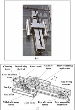
Mechanical construction of the robot
The robot can automatically climb in the up-down direction and clean in the right-left direction. It will take the tracks on the wall as supports for climbing up and down between layers and moving sideways on one layer around the ellipsoid. The body consists of the climbing mechanism, the moving mechanism, two cleaning brushes and the supporting mechanisms. The robot is 3 meters long, 1.5 meters wide and 0.4 meter high.
The degree of freedom of the robot is demonstrated in Fig. 3. There are altogether 25 joints, out of which 17 joints are active and are actuated by respective DC motors. In this Fig., “P” means the linear movement joint and “R” means the rotating movement joint.

Degree of freedom
In order to meet the requirements of light weight and a dexterous movement mechanism, considerable stress is laid on weight reduction as well as on construction stiffness. Most of the mechanical parts are designed specifically and mainly manufactured in aluminum. The main body of the robot is made up of two frames: the main frame and the auxiliary frame. The auxiliary frame is actuated by the DC motor and the belt, both of which are mounted on the top of the main frame. It can slide along the main frame. Other functional parts are all mounted on these two frames. The auxiliary frame has a shape like an “n” encircling the main frame so that the safety and the reliability of the movement are satisfied (shown in Fig. 4).

Sliding-mate between two frames
A special slide bar made of polyethylene material is designed to create a sliding-mate between the two frames thus saving the weight of the linear guidance which is usually used to realize this kind of structure. Two rotating brushes mounted on the auxiliary frame can move up and down automatically and rotate for cleaning when the robot moves sideways along the tracks.
There are two pairs of clutches (shown in Fig. 5) on the main frame and the auxiliary frame respectively whose functions are grasping the sliding-rods which can safely slide along the track but cannot be detached from it. The sliding-rods are designed to be the medium between the track and the robot in order to avoid the safety problem caused by the robot directly grasping the track. A DC motor is embedded in the mechanical clutch which allows for a very slight structure. Three switches on the top, in the middle and on the bottom are used to feedback its vertical movement.
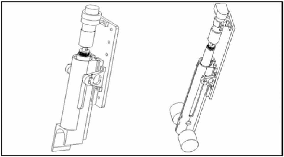
The clutch and the supporting mechanism
When the robot is working on such a half-ellipsoid, obstacles and friction make it almost impossible to attach a safety wire to the robot from the theater top. As a result, a mechanical structure named abdominal plate was developed and designed to solve the safety problem. While a set of clutches hold the sliding-rod to avoid falling down, abdominal plates on the robot are interposed between two little wheels on the sliding-rod to avoid capsizing out of the wall (shown in Fig. 3 and 4).
A front supporting mechanism and a rear supporting mechanism with the same structure as the clutches are used to adjust the orientation of the robot and support the body on the surface. There are two supporting wheels on the tip of the mechanism in order to increase the area of interaction and avoid damaging the outer surface (shown in Fig. 5). The wheels give a passive turning motion when the robot is climbing in the up-down direction.
A front and a rear wheel sets which are used to provide the sideways driving force for the robot when they are clamped on the tracks are also installed on the axis of the main frame. The rear wheel set can move passively along the middle axis of the main frame in order to suit the various sizes of the planks which are due to the special arc shape of the surface (as shown in Fig. 6). A linear guidance connects the whole set and the main frame, which permits a passive sliding. The lifting DC motor can lift and lower the whole set to adapt to the height of the track.

Mechanical structure of the wheel set
3. Climbing planning
Fig. 7 shows the process of climbing from one layer to the next. In this process the brush sets are all in the upstate (no contact with plank). (a) The robot is in its home state: clutches on the main and auxiliary frame are all in the down-state to hold the sliding-rod on track1 and on track2 respectively; the abdominal plate is inserted in both two sliding-rods; the two supporting mechanisms are all in the up-state. (b) Clutches on the auxiliary frame are raised, and the auxiliary frame is pulled up along the main frame. (c) The motion of the auxiliary frame stops when the clutches on it are right above track2. Then the clutches are lowered to grip the sliding-rod. (d) Clutches on the main frame are raised; the front supporting mechanism touches down on plank1. (e) The main frame moves up. When the abdominal plate is out of the sliding-rod on track1 and the rear supporting mechanism is above plank1, the main frame stops moving and the rear supporting mechanism touches down on plank1. (f) The front supporting mechanism is raised, and the main frame continues to move up. When the front supporting mechanism is above plank2, it touches down on plank2. (g) The upward movement of the main frame does not stop until track3 is detected by the front ultrasonic sensor. Then the front or rear supporting mechanism is adjusted to position the robot parallel to plank2. Afterwards, the main frame moves up to insert the abdominal plate into the sliding-rod on track3. (h) The motion of the main frame stops when the clutches on it are right above track3. Then the clutches are lowered to grip the sliding-rod on track3. The robot is now in its home state again, and the process of climbing up to the next layer is over.

Climbing planning
4. Design of the ditributed control system
4.1. Distributed Control System Based on CAN Bus
Five key issues are essential for this big and complicated robotic control system: a) functionality, b) safety c) extensibility, d) easy handling, e) and low cost. A distributed control system based on CAN bus is adopted to satisfy these issues, as shown in Fig. 8. The system is divided into 6 parts, five CAN bus control nodes and a remote controller.

Control system
The PCM-9575 IPC is the core part of the control system. The PCM-9575 is a new EBX form factor 5.25″ single board computer (SBC) with an onboard VIA Embedded low power Ezra 800 MHz. The VIA Eden processor uses advanced 0.13μ CMOS technology with 128KB L1 cache memory and 64KB L2 cache memory. This board can operate without a fan at temperatures up to 60° C and typically consumes fewer than 14 Watts while supporting numerous peripherals. This SBC includes a 4X AGP controller, a PCI audio interface, a PCI Ethernet interface, and 2 channel LVDS interfaces. Its design is based on the EBX form factor that supports the PC/104- Plus interface for ISA/PCI module upgrades. Other onboard features include a PCI slot, an LPT, 2 USBs, IrDA and 4 serial ports.
A PCM3680 card is used as a communication interface with PC/104-Plus interface for the main node and the other CAN nodes. The main computer node is a higherlevel controller and does not take part in joint motion control. The responsibilities of the main computer node include receiving orders from the remote controller, planning operational processes, receiving feedback information from other nodes, and giving orders to other nodes. The other four lower-level nodes are responsible for receiving orders from the main computer node and directly controlling respective joint motors.
It is important for the control system to realize precise position control when the robot moves vertically from one layer of planks to another. On the other hand, some joints such as brushes and clutches are only needed for ordinary on-off control. Two kinds of CAN nodes, both designed by us, which are mainly based on the P80C592 micro-chip are included in the control system in order to meet the requirements of functionality, extensibility and low cost. Each node is in charge of a special function in which all the related sensor signals are included. For example, the supporting mechanism node can directly count the pulse signals from the encoder, deal with the signals from the touchable sensors and other magnetic sensors, and directly drive the DC motors in the front and rear supporting mechanisms. In order to satisfy the requirement of extensibility, there are enough I/O resources on the control node, which make it easy to attach sensors and sensor processing equipment. At the same time multiple process programming capability is guaranteed by the principle of CAN bus.
The controlling and monitoring of the robot is achieved through the digitalized CCD camera and a wireless graphical user interface (GUI) which allows an effective and user friendly operation of the robot. Once the global task commands are entered by the user, the robot should keep itself attached to and move on the surface while accomplishing the cleaning tasks. All information while working will be sent back to and displayed on the GUI during the phase of the feedback. The commands should first be remembered in order to check out their rationality and security. The following part includes command interpretation, task-level scheduling, and motion planning.
4.2. Sensor System
Multiple sensing and control systems are incorporated to handle uncertainties in the complex environment and realize an intelligent climbing and cleaning motion. Software should be dexterous enough to identify the various geometries of the wall and intelligent enough to autonomously reconstruct the environment. On the outer surface of the working target there are some LED-lamps, decorating belts and tracks. The robot's body does not interact with the planks due to the special mechanical structure. The tracks and the sliding-rod on the building surface are two important targets to be detected when the robot is climbing and cleaning.
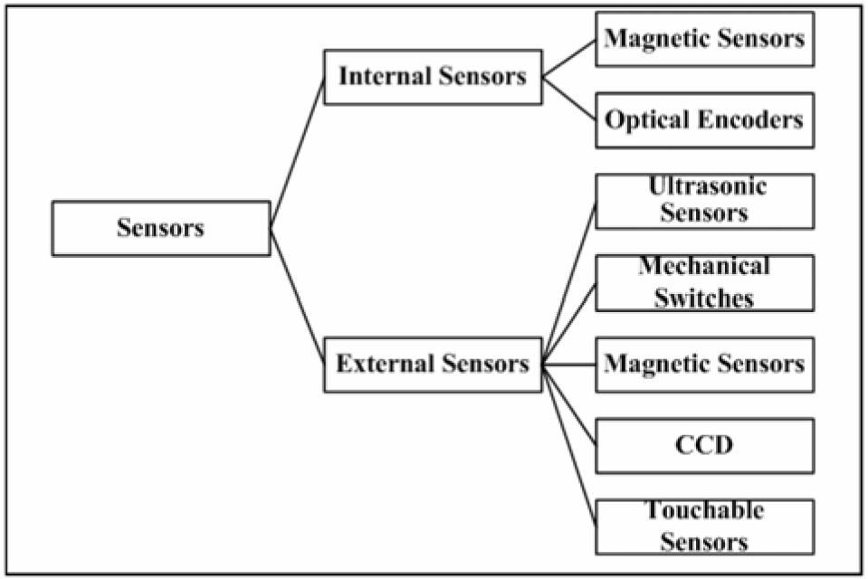
All the sensors on the robot, which can be divided into external and internal sensors, are shown in Fig. 9. The internal sensors reflect the self-status of the robot. There are 48 limit switches in total. For each active joint, magnetic limit switches give the controller the position of the joint. In order to increase the detecting diameter, a magnetic metal slice is placed on a special position. The testing results show that the reliability of the sensor signal is guaranteed and the diameter for detecting is 0–3mm which is enough. For the climbing movement mechanism and the supporting mechanisms where the accurate position is needed, the HEDL55 optical encoders made by MAXON are used. The IPC can directly count the pulse signals from the encoder using the interruption.
Sensor system
The external sensors are responsible for collecting information about the operational environment. All of them are very important for working safety. There are three ultrasonic analog sensors placed in the front, in the middle and in the rear parts respectively. Firstly they can be used to detect the sliding-rod in the moving direction. The accuracy of the sensors' output is affected by three issues including the temperature, the distance for detection, and the reflection performance of the objects. The US25 made by TAKEX Company are chosen for our control system. The distance for detection is 5–25mm; the precision for distinguishing is 40mV/mm; the velocity for responding is 50ms and the operating temperature is −10–55 degrees Celsius. The outputs of the ultrasonic analog sensor when detecting sliding-rods on the plank are shown in Fig. 10. There is an outshoot if the sensor detects something above the plank. On the other hand, any two signals can be used to compute the angle between the robot frame and the plank. In order to obtain the precise data, the software will firstly choose the data and get rid of the mistakes, and then the middle filter and the average filter are used for correcting the data, which finally yields the accurate data for computing. There are two touchable sensors on the tip of the front and the rear supporting mechanisms, which are used to monitor the interacting condition of these supporting mechanisms and to determine whether the attachment to the glass surface is stable.

Experiment result of the ultrasonic sensor
After the position of the sliding-rod is found during the climbing movement, the robot main frame should be set down and contacted with the sliding-rod controlled by the supporting mechanisms. We designed a kind of mechanical touchable sensor for detecting the interaction between the main frame and the sliding-rod. Fig. 11(a) shows the real structure. Here a mechanical parallelogram is used. When the bottom of the main frame touches the sliding-rod, the contact force makes the parallelogram deform, then the magnetic sensor will send a signal to the controller as soon as it has detected the metal piece.

Principles of some external sensors
On the other hand, the magnetic sensors are used for monitoring how safe the connection between the abdominal plate and the sliding-rod is (shown in Fig. 11(b)). When the robot is working, there should be at least one magnetic sensor available for detecting of the abdominal plates inserted between two little wheels on the sliding-rod.
Some magnetic sensors are mounted on the clutches in order to ensure reliability when the clutches set out to grasp the sliding-rod. The process of grasping is shown in Fig. 12.
The clutch is positioned over the sliding-rod in order to satisfy the following formula: L>D/2; The clutch is put down until the middle switch on the clutch mechanism gives a signal; The movement of the clutch towards the sliding-rod will stop when the magnetic sensor is available; The clutch is lowered until the process is finished.

The process of grasping a sliding-rod
5. Conclusions
In contrast to conventional theoretical research, this project finishes the following innovative work:
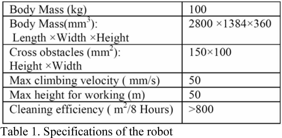
This paper described a new kind of auto-climbing outer walls climbing robot used for cleaning the complex outer curve surface of the National Grand Theater in China. Fig. 13 shows the robot climbing up in the same process as Fig. 7. A novel and special movement mechanism is developed and designed to satisfy weight and dexterity requirements. Table 1 summarizes the main specification features of the robot. An intelligent control system based on CAN bus is designed to control the robot. The advantages and the characteristics are analyzed. Some key issues such as sensor technology, which is necessary for such an autonomous robot, are studied in detail.

Real climbing experiment.
Specifications of the robot