
Abstract
Due to ultraviolet flux in the surface layers of most solar bodies, future astrobiological research is increasingly seeking to conduct subsurface penetration and drilling to detect chemical signature for extant or extinct life. To address this issue, we present a micro-penetrator concept (mass < 10 kg) that is suited for extraterrestrial planetary deployment and in situ investigation of chemical and physical properties. The instrumentation in this concept is a bio-inspired drill to access material beneath sterile surface layer for biomarker detection. The proposed drill represents a novel concept of two-valve-reciprocating motion, inspired by the working mechanism of wood wasp ovipositors. It is lightweight (0.5 kg), driven at low power (3 W), and able to drill deep (1-2 m). Tests have shown that the reciprocating drill is feasible and has potential of improving drill efficiency without using any external force. The overall penetration system provides a small, light and energy efficient solution to in situ astrobiological studies, which is crucial for space engineering. Such a micro-penetrator can be used for exploration of terrestrial-type planets or other small bodies of the solar system with the minimum of modifications.
Introduction
A major goal of future astrobiological missions (e.g. to Mars, Europa and asteroids) is to search for biomarkers - organic molecules that might reveal the presence of extraterrestrial prebiotic and biotic signatures. Although both sample return and in situ analyses can address these goals, the rapid development of microfluidic lab-on-a-chip systems, the complex logistics of sample return compared with in situ missions, and back-contamination issues suggest that in situ analysis is an approach that must be seriously considered. Recent studies show that due to turnover of the solar bodies, the surface layers will not permit survival of organic molecules that decays on UV/oxidant exposure over aeons to carbon dioxide and other residues. We need to penetrate below the sterile layer to access organic materials, e.g. on Mars this layer is estimated at −2 m thick [Ellery et al., 2003]. Surface penetrators provide modest cost solution for such in situ astrobiological investigation. The advantage of the penetrator is that it imposes minimal mass overheads in comparison with other robotic devices. A few examples of planetary penetrators include Mars 96, Deep Space 2 microprobe, etc. The DS2 microprobe provides a baseline of our design.
In this paper, a micro-penetrator/drill package is outlined by virtue of the general deployability at low cost. The micro-penetrator is likely to reach about 1 m depth through regolith/compacted regolith. The bio-inspired drill serves the purpose of drilling 1–2 m deeper beneath the surface and taking samples. This miniaturized system indicates some enhanced utility that is incorporated into an engineered system inspired from a biological system. Such enhanced utility is critical for space mission designs where premium is placed on mass, volume and power. Biological systems are similarly constrained making biomimetic technology uniquely suited as a model of miniaturized systems.
The rest of the paper is organized as follows: Section 2 outlines the system requirement and design constraints. The following section presents a conceptual design of the micro-penetrator in terms of configuration, scientific instruments, material and structure, flight dynamics, communication, power and energy, and penetration model. To perform system-level design, a near earth asteroid mission scenario is assumed. Feasibility study and preliminary design of the biomimetic drill are provided in Section 4. Lab-based experiments have demonstrated the feasibility of the novel drill concept. Last section concludes the paper.
System Requirement & Design Constraints
Penetration depth: 0.5–1 m
Drilling depth: 1–2 m
Overall mass budget: 10 kg
Micro-Penetrator Description
The surface micro-penetrator is an adaptation of the terradynamic vehicles to planetary landers. It is a self-sufficient space probe equipped with control systems and other devices to ensure its motion after separation from the spacecraft, descent into the atmosphere, penetrating into the solar bodies, subsequent measurements, and transmission of scientific information to the orbiter for relay to Earth.
Configuration
As shown in Fig. 1, the penetrator is envisaged with two main parts: the penetrating part (forebody) and the afterbody, which remains on the surface. An umbilical cable connects the two parts.
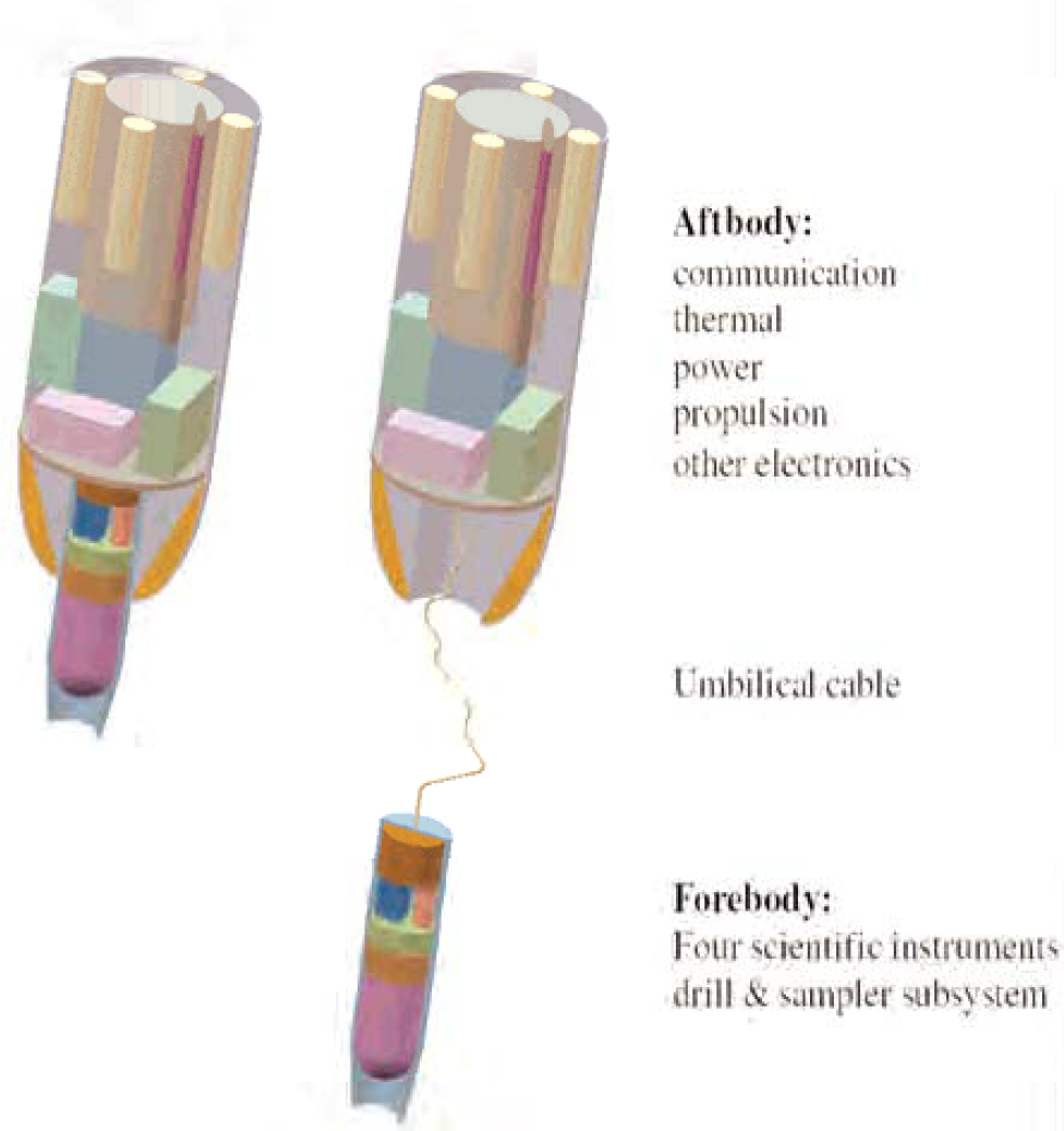
Micro-penetrator configuration: before (left) and after separation (right)
The forebody of the penetrator is cylinder-shaped and hollow to accommodate the principal science and electronics. Starting at the nose, the conic shape has an aspect ratio (i.e. length to diameter) of 2:1 to provide an initial low resistance to penetration. The nose is blunted with half of the original length removed to improve ricochet resistance and prevent the penetrator from bouncing back. Starting from the nose segment includes the drill and sampler subsystem. The forward diameter of the penetrator shaft is 5 cm and length is 15 cm to accommodation four major scientific instruments, including biomarker chip, seismometer, accelerometer, and thermometer (refer to Fig. 2). Aftbody is the cylindered terrabrake, which extends to a station 25 cm aft of the forebody with a base diameter of 15 cm, designed to arrest and absorb the impact in the surface materials of intermediate to high penetrability. At the back end of the terrabrake is sufficient volume to place the propulsion, power cells, thermal and communication subsystems. As the forebody penetrates below the surface, the separable afterbody is left behind on the surface for communication purpose.
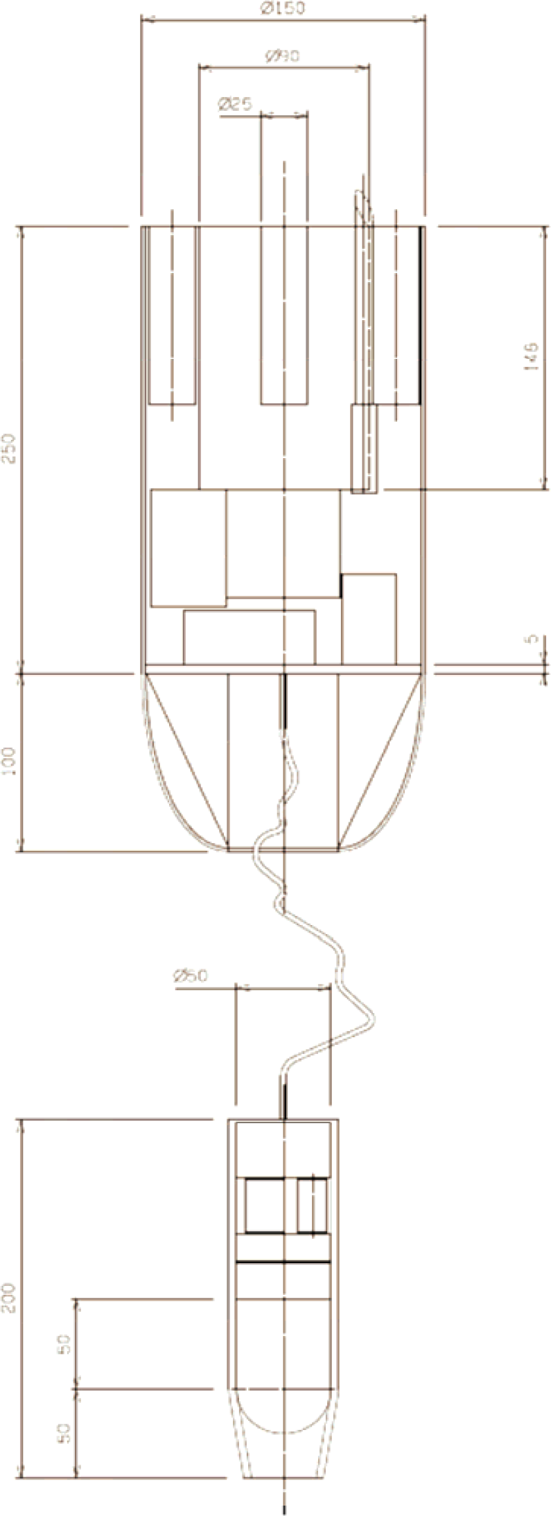
Engineering diagram of micro-penetrator
After penetration, the afterbody remains connected to the penetrator with a multiconnector umbilical that is paid out from the aft section of the forebody during the penetration. A sequence of science experiments is then conducted during the life of the penetrator and the data stored in an onboard memory until it can be transmitted to an orbiting spacecraft for relay to Earth.
Irrespective of how novel the micro-penetrator/drill package may be or how challenging the engineering task of designing a penetration system, the only justification for such a concept is how well it serves as a platform for the conduct of high priority science.
Over the last decade, the drive to miniaturize common laboratory techniques has produced systems that are relevant for astrobiological research and solar system exploration. This has enhanced the feasibility and capabilities of in situ biomarker detection on extraterrestrial planets. Given mass budget of the system in Section 0, three existing biomarker detectors are chosen as potential candidates for the system. They include two biomarker chips and one laser Raman spectrometer: 1) microfabricated organic analyzer (MOA) by UC Beckley, JPL and UCSD, USA [Skelley et al, 2005]; 2) life marker chip by Leicester and Cranfield Universities, UK [Sims et al, 2003], and 3) Confocal Microscope and Raman Spectrometer (CMaRS) by Montana State University, USA [Dickensheets, 2000].
To maximize the scientific return within the engineering constraints, we have considered a complete sensor suite as shown in Table 1 to facilitate in situ measurements and experiments.
Scientific instruments and experiments

Scientific instruments and experiments
The forebody structure is assumed to be a shell composed of Titanium, which has the advantage of having high yield strength, and the ability to deform before buckling. Currently a simple 4-mm-thick tube is assumed for the outer structure. For extra impact protection at the nose tip, this could be fanned out to be thicker. A parametric estimate of the structure mass assumes it to be 20% of the overall aftbody mass. Extensive use of crushable Honeycomb is envisaged to be able to cushion the shocks from the impact. Plates with hardware attached, are assumed to be thick enough to avoid buckling through critical bending.
Propulsion & Avionics
On-board cold-gas propulsion system could first separate the micro-penetrator from the orbiter, place it into the controlled orbit around a 1.5-km-diameter asteroid at 3 km altitude (e.g. 1996 FG3), and assist further trajectory control. The orbital velocity is only −0.2 m/s in this case, which requires additional propellant to increase the micro-penetrator velocity to −150 m/s and achieve the desired penetration depth (refer to Section 2). As a relatively high acceleration is required due to the short distance to travel, a small solid motor is envisaged, such as a derivative of the Marc 36A1 by Atlantic Research. Attitude control and decent guidance has assumed EADS Inertial Measurement Unit with a simple processor and a cold gas reaction control system.
Communication
Due to the short ranges involved, communications between the micro-penetrator and the orbiter can be done by a low power, omni directional link. The link between the orbiter and the micro-penetrator is a simple, low power UHF system. A 0.6 m Medium Gain Antenna on the orbiter is designed.
Power & Energy
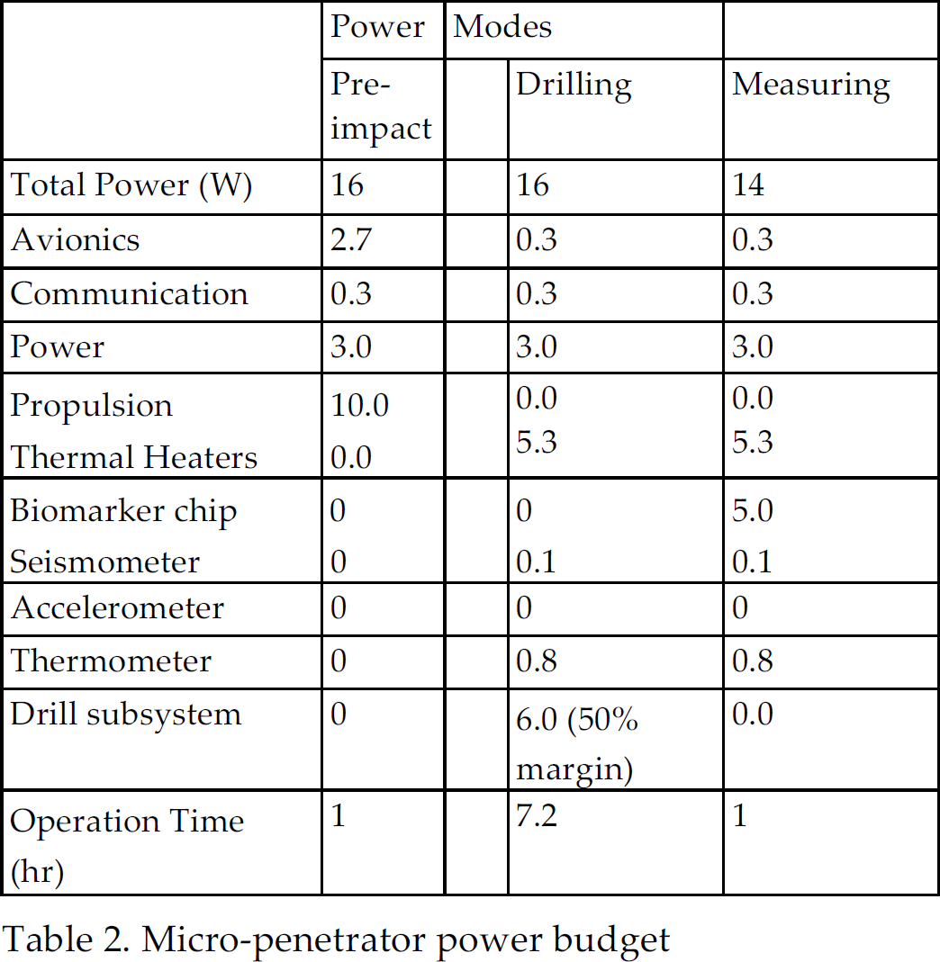
Table 2 provides the power budget of the micro-penetrator. Based on the preliminary design, overall energy budget is around 140 W-hr. This includes 50% safe margin for the drill power consumption. A primary LiSOC12 battery has been selected as the baseline for simplicity and cost. This is composed of 8 Tadiran TL-6526 batteries in 4 vertical stacks around the central solid motor.
Micro-penetrator power budget
Micro-penetrator power budget
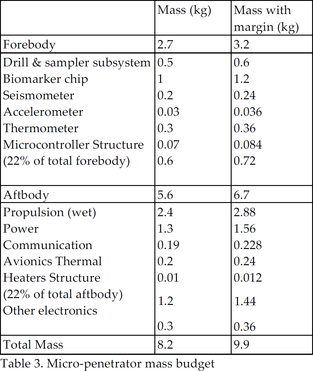
Given the above-mentioned design, an overall mass budget sheet is provided in Table 3. The system is estimated to have an all-up mass of less than 10 kg including a 20% system-level mass margin.
Micro-penetrator mass budget
Micro-penetrator mass budget
Penetration model is applied both to predict the penetration depth in a specified target, and to infer the target properties from penetration measurements. A widely used formalism is Young's empirical equation, also known as the Sandia equation, in the form of [Young 1997]:

For blunted conic nose, we have

Biological Ovipositor Drill
Wood wasp uses its ovipositor to drill holes into trees in order to lay its eggs. The ovipositor uses a reciprocating motion to drill into the wood and has a series of different teeth to cut and remove the wood and sawdust. Vincent and King studied the working mechanism of wasp ovipositors in [Vincent & King, 1995]. As shown in Fig. 3, the wood wasp ovipositor can be split into two significant halves: one side is the cutting teeth and the other is the pocket for the sawdust to be carried away from the hole. The cutting teeth are used to cut the wood in compression without the fear of buckling. The push teeth are arranged in a staggered pattern in order to even out the forces required in cutting. The sawdust from the cutting teeth is deposited into the pockets that then carry it to the surface on the upstroke. Two sides repeat this process in a reciprocating motion.

Wood wasp ovipositor [Vincent & King, 1995]
The ovipositor drill uses reciprocating rather than rotatory and percussive motion. The drill bit is composed of two valves that can slide against each other longitudinally as depicted in Fig. 4. Rather than the helical sculpturing of a rotatory drill, the reciprocating drill has backward-pointing teeth that present little resistance to being moved downwards but engage with the surrounding substrate to resist being moved in the opposite direction. Once the teeth are engaged, the tensile force that can be resisted, tending to pull the drill out of the substrate, allows the generation of an equal and opposite force in the other valve tending to push it further into the substrate. The drilling force is generated between the two valves and there is no net external force required. Another intriguing aspect of the reciprocating is how the drilling debris is disposed. Since the two valves are moving in opposite directions, the debris is moved up from the hole rather than deeper into it.
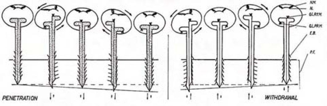
Biological ovipositor drill
Conventional rotary drills work on compression (e.g. Rosetta/SD2), which suffers from big mass, buckling problems, high power requirements and bit dulling/breaking/jamming. Another major limitation using conventional drills on low gravity environment in outer space is the need for high axial force. This will again add penalty in terms of design complexity and mass. Though some drills working on percussive motion (e.g. Beagle 2/Mole, Ultrasonic/sonic/drilling/coring (USDC)) may offer low power consumption, their drilling rate is slow.
To minimize power for effective drilling, structure and geometry are two factors to be considered in the design of drill bit. Fig. 5 illustrates the proposed design for the experiments in the later section. The drill bit is constructed from half cones (increasing in diameter) and the edges of the cones carry out the griping and cutting action.
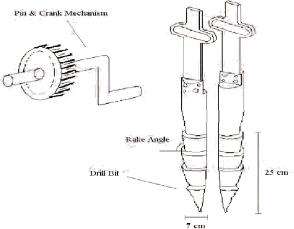
Drill test model
In order to meet the major design requirement in terms of size, weight and power, the choice of drive mechanism and actuation source is restricted. The pin & crank mechanism (see Fig. 5) is chosen to drive the drill, which offers the simplest and most compact way to transform motions. Normal electromagnetic motors tend to incorporate heavy metal components, have slow response and slack with power. One reasonable choice of actuation source is a piezoelectric motor. Piezoelectric motor show superior torque and response time relative to existing magnetic motors of their low profile shape
Lab-Based Experiments
Test Apparatus
For testing purposes the drill bit were manufactured with different rake angles using a Rapid Prototype (RP) machine. The RP machine uses ABS plastic to manufacture the drill bits and thus that restricts the choice of workpiece. Tests at this stage are conducted on condensed polystyrene. The main aim of this experiment was to measure forces (in the x and y direction) required to cut through the workpiece. The apparatus set up that was used to record measurements of the cutting forces includes:
Triple Power Supply Circuit (Supplying 15V) A/C Speed Controller Voltmeter Transducer/Transducer Circuit Force balance
Cutting Speed
A/C speed controller is used to tune down the voltage supply to the drill bit such that variable speed can be achieved. The speed of the cutting process is obtained via a transducer that is attached to the gearbox. The transducer reads the number of teeth on the motor-gear that pass its sensor per minute, dividing this frequency by the number of teeth on the motor-gear gives the RPM of the motor. The pin and crank design within the gear box means that every half revolution the blade travels through one stroke, hence the cutting speed of the blade is given by RPM/2.
The transducer circuit reads the frequency of the motor-gear teeth passing by the sensor and gives the output reading as a voltage (red via a voltmeter). The circuit is programmed such that the output voltage from the transducer is proportional to the output frequency of the gear teeth. By calibrating the maximum voltage to give maximum frequency and zero voltage to give zero frequency, a relationship between the voltage and frequency is generated such that variable motor speed gives variable output voltage via the transducer, which corresponds to a cutting frequency, i.e. maximum voltage of 10 V corresponds to maximum frequency of 2360 Hz and minimum voltage of 0 V corresponds to minimum frequency of 0 Hz. Linear proportionality gives Frequency = 236 * Voltage.
Experimental Results
Four different drill bits are tested with rake angles of 10, 20, 30, and 40 degrees. The horizontal and side cutting forces were measured using a force balance for each drill bit, at variable cutting speed.
Test results are illustrated in following figures, where polynomial trend line is used based on 10 sampling data to accommodation potential measuring errors. In this test, cutting velocity operates within a range of 0-0.4 m/s. Fig. 6 shows that the cutting force increases as the cutting velocity increases initially and gradually decays afterwards. This results in the total output power to behave as shown in Fig. 7. Therefore, there exists a optimum value of the cutting speed that corresponds to a peak output power. Both figures also indicate that under same cutting speed, the drill bit with higher rake angle produces larger cutting force and output power. To generate higher output power, bigger rake angle is recommended for the drill bit design.

Cutting force versus cutting velocity
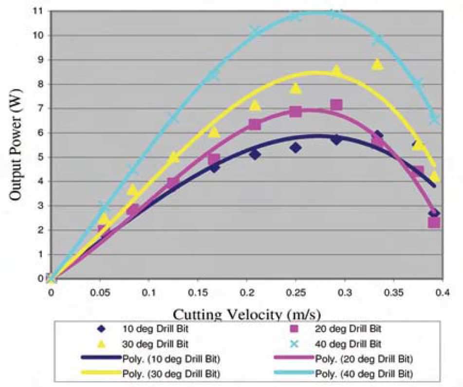
Output power versus cutting velocity
This paper outlines a micro-penetrator concept that provides a compact solution to in situ astrobiological investigation. A novel drilling concept inspired from biological ovipositor drill has been proposed as an onboard instrument to sample beneath the sterile surface layer for biomarker detection. The ovipositor drill represents a novel concept of two-valve-reciprocating drilling that requires no overhead force. Feasibility of such drilling mechanism has been shown through lab-based experiments. The preliminary envisaged penetrator/drill system is able to reach ~2 m underneath planetary surface and kept within mass budget of 10 kg. Such a microprobe can be deployed for the exploration of terrestrial-type planets or other small solar bodies with the minimum of modifications. Further study is necessary to investigate the drill performance with metal drill bit on a wide range of substrates. A complete design of the drill as a subsystem of the penetrator will be further studies.
Footnotes
Acknowledgement
This work was supported by ESA under bionics & space system design contract AO/1-4469/03/NL/SFe [Ellery, et. al, 2005].