
Abstract
A new kind of pneumatic climbing robot is presented to meet the requirements of glass-wall cleaning for high-rise buildings, which is totally actuated by pneumatic cylinders and attached to the glass wall with vacuum suckers. Using the pneumatic actuators the climbing robot can be made lightweight and dexterous. At the same time the movement driven by pneumatic actuators has the characteristic of passive compliance. In order to solve the problems of high speed movement for the Y cylinder and precise position control of the X cylinder, the applied pneumatic schemes of X and Y cylinders are employed to drive the high-speed on-off solenoid valves and an ordinary valve to adjust the air-flow and pressure to the cylinders. Furthermore a method of segment and variable bang-bang controller is proposed to implement the accurate control of the position servo system for the X cylinder during the sideways movement. Testing results show that the novel approach can effectively improve the control quality. This cleaning robot can meet the requirements of realization.
Introduction
Climbing robots are useful devices that can be adopted in a variety of applications such as reliable non-destructive evaluation (NDE) and diagnosis in some hazardous environments (Briones, L. et al., 1994), welding and manipulation in the construction industry especially of metallic structures (Armada, M. et al., 1998), cleaning and maintenance of high-rise buildings (Zhang, H. et al., 2005). The emphasis for discussion in this paper is on the cleaning robot on high-rise buildings.
Pneumatic technology offers some advantages for application: low cost, high power-to-weight ratio and cleanliness. It is widely used in the field of industry. A kind of pneumatic cleaning robot has been developed in Japan (Nishigami, M. et al., 1992), but it cannot walk sideways. The group at the Robotics Institute of Beihang University developed two kinds of autonomous pneumatic climbing robots (Zhang, H. et al., 2004) with sliding frames for glass-wall cleaning. The first model has only limited dexterity and can not work on a vertical wall. The second prototype is very portable and the cleaning efficiency is about 75 m2/ hour.
However the pneumatic system has the characteristic of nonlinearities. These make precise position control difficult to achieve. To cope with this problem, a lot of research work including fuzzy control (Thongchet, S. et al., 2001), neural networks (Choi, G.S. et al., 1998) and extended PID control (Aziz, S. et al., 2000), has been devoted to the development of various position control systems for pneumatic actuators.
In this paper, taking Shanghai Science and Technology Museum as the operation target, a new kind of cleaning robot named Sky Cleaner 3 which is actuated by pneumatic cylinders and attached to the glass wall with vacuum suckers is presented. The project is intended to develop an automatic and fully pneumatic robotic system for cleaning glass walls of high-rise buildings. This paper is organized as follows: in section 2, an overview of the robotic system is given. Then section 3 presents the pneumatic schemes of the robot. In order to solve the problems of lower stiffness and the nonlinear movement characteristic of the pneumatic system, in section 4 a method of segment and variable bang-bang controller is proposed to implement the accurate control of the pneumatic X-cylinder-position servo system. At last section 5 gives a conclusion.
Overview of the robotic system
The motivation of developing this kind of robot is to clean the outer wall of high-rise buildings. Efficient cleaning is the ultimate aim. The robot should have functions to move in both the up-down direction as well as the right-left direction. From this point of view, the cleaning equipment such as an adaptive cleaning head and effective moving structure are needed for the cleaning robotic system.
On the other side the climbing robot has to be safely attached to the glass wall and has to overcome its gravity. There are four different principles of adhesion used by climbing robots: vacuum suckers, negative pressure, propellers and grasping grippers. Each one has some advantages and some disadvantages at the same time. The mechanical structure for safe and reliable attachment to the glass surface is needed for sure.
Working target
Sky Cleaner 3 is a real product designed for cleaning the complicated curve of the Shanghai Science and Technology Museum (as shown in Fig. 1). The building top is 40 m from the ground. From left to right its height gradually decreases. The total surface area of the outer wall is about 5000 m2.
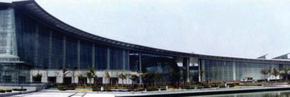
Shanghai Science and Technology Museum
The robotic system consists of three parts: 1) a following unit; 2) a supporting vehicle; 3) the cleaning robot. Sky Cleaner 3 is supported above by cables from the following unit mounted on the top of the building. All following movements of the unit which protects against falling due to any type of malfunction are synchronized by the robot itself. A hose for water, a tube for pressurized air, and cables for control signals are provided from the supporting vehicle on the ground. Meanwhile, the following cables carry some weight of the hose and tube when the robot is in mid-air.
Sky Cleaner 3 is shown in Fig. 2. A novel and special movement mechanism actuated fully by pneumatic cylinders is developed to satisfy the lightweight and dexterity requirements. The robot features 14 suction pads which can carry a payload of approximately 60 kg including the body weight. Two cross-connected rodless cylinders which are named X and Y, compose the main body of the robot. A turning waist joint actuated by a pendulum cylinder connects the X and Y cylinders. The waist joint is used for the correction of inclination during the robot's movement. For a turning action, the position-pin cylinder is aired to release the locking pin, so that turning motions can be actuated by the waist pendulum cylinder. At present the robot rotates to a relatively small degree (2°) per step.

Mechanical structure of Sky Cleaner 3
At the ends of the X and Y cylinders are four connected short-stroke foot cylinders named Z, whose function is to lift or lower the vacuum suckers in the Z direction and support the body on the wall. In order to move from one column of glasses to another in the right-left direction, a specially designed ankle joint gives a passive turning motion to the suckers, as shown in Fig.3. This joint is located between the connecting piece which joins the vacuum suckers with the Y cylinder and the plank beneath it to which 4 vacuum-suckers are attached.

The joint of the vacuum suckers
Some sensors that can detect window obstacles are mounted on each end of the X and Y cylinders. On opposite ends in the Y direction there are also four brush cylinders which actuate the brushes up and down. An adaptive cleaning head is designed especially for effective cleaning, equipped with a drainage collecting device. When the glass is being cleaned, the water is drawn off the glass wall through a vacuum pump. Then the water flows down because of the gravity and is collected on the supporting vehicle on the ground. At last the drainage is filtered, and then reused for cleaning.
A programmable logic controller (PLC) is used for the robot control system because of its high stability and modularity, as shown in Fig. 4. The PLC can count the pulse signals from the encoder and directly drive solenoid valves, relays and vacuum ejectors. There are two kinds of external sensors on the robot: touchable sensors and ultrasonic analog sensors, which are responsible for collecting information about the operational environment. The internal sensors are to reflect the self-status of the robot. The waist sensor sends a signal to the controller once the inclination of the main body is about 2 degrees. The vacuum sensors are used to monitor the vacuum condition of the suckers and determine whether the suction on the glass is stable.
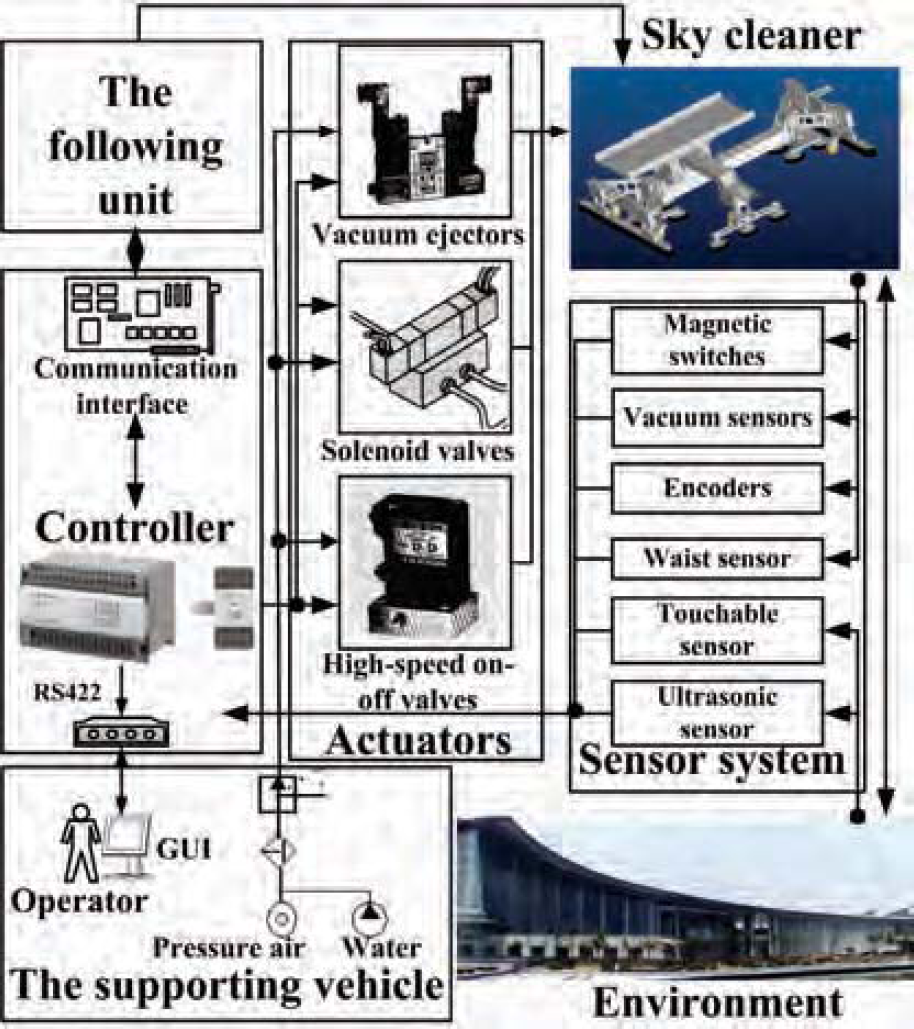
Control system
A specific cleaning trajectory is essential for the cleaning movement to cover all the unoccupied areas in the environment (Xu, F. et al., 2003). Area-covering operation also named complete coverage path planning (Oh, J.S. et al., 2003) is a common and useful kind of path planning, which requires the robot path to cover every part of the workspace. The standards of choice and evaluation for the different kinds of path planning should synthesize work safety, cleaning efficiency and the percentage of cleaning coverage. A robotic cleaning system can relieve workers of their hazardous work and make the automatic cleaning of high-rise buildings possible. Work safety is the first important factor for evaluating the path trajectory of a wall-cleaning robot. Additionally, it can improve the technological level and productivity of the service industry in building maintenance. Even if it is very reliable, the cleaning robot is still not a satisfactory product if it takes longer to clean a certain area than human workers would. The robot should find an efficient cleaning trajectory to carry out its work. At the same time, the percentage of cleaning coverage is also very important from the practical point of view. It would be unacceptable for the robotic system to only achieve the cleaning of selected parts of the target surface while human workers in a gondola can clean it almost 100%.
For Sky Cleaner 3, if the robot cleans the work target in the right-left direction, it has to cross two-degree-angle edges several times. But it can work and clean uninhibited in the vertical direction, because that way the glasses are considered as forming a plane. As a result, the robot begins to clean the glass wall from the upper left point, and then works its way down. It moves to another column when the first column of glasses is finished cleaning, as shown in Fig. 5. The coverage percentage on this small working area is over 93% and the cleaning efficiency is 125 m2/ hour.
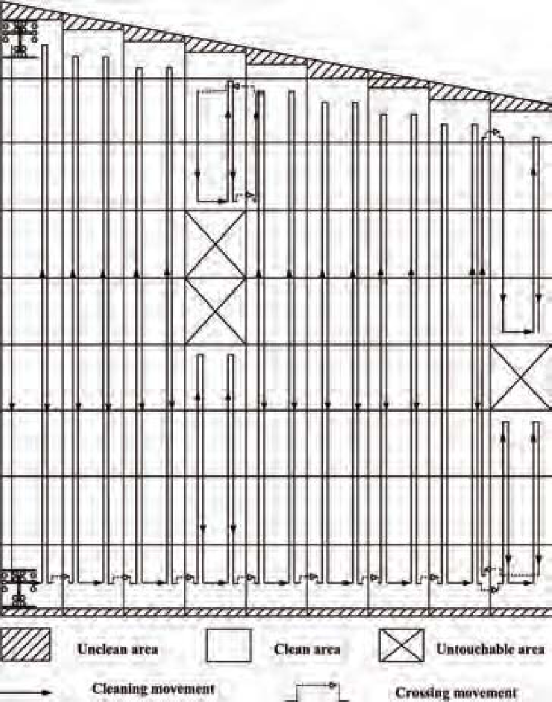
Cleaning planning
There are two reasons for designing fully pneumatic cleaning robots. Firstly, the climbing robot can be made lightweight and dexterous using the pneumatic actuators. Here the definition of “Power-to-weight ratio” is the ratio of the drive force Fdrive to the weight Gdrive of driver construction. A linear cylinder is 1–2 times lighter than a motor-driven linear-motion unit with the similar specifications (shown in Table 1).
Contrast between pneumatic actuators and electrical actuators

Contrast between pneumatic actuators and electrical actuators
Secondly, the movement driven by pneumatic actuators has the characteristic of passive compliance due to the compressibility of the air, thus makes the robot safer than being driven by motors under the situation of interacting with the brittle glass.
The pneumatic system of Sky Cleaner 3 includes X, Y and Z cylinders, a waist cylinder, brush cylinders and the vacuum suckers. The practicable suction method on glass panes is to use vacuum suckers that are generally controlled by a vacuum ejector (Fig. 6). It shares the compressed air source with other pneumatic cylinders, which simplifies the whole system.
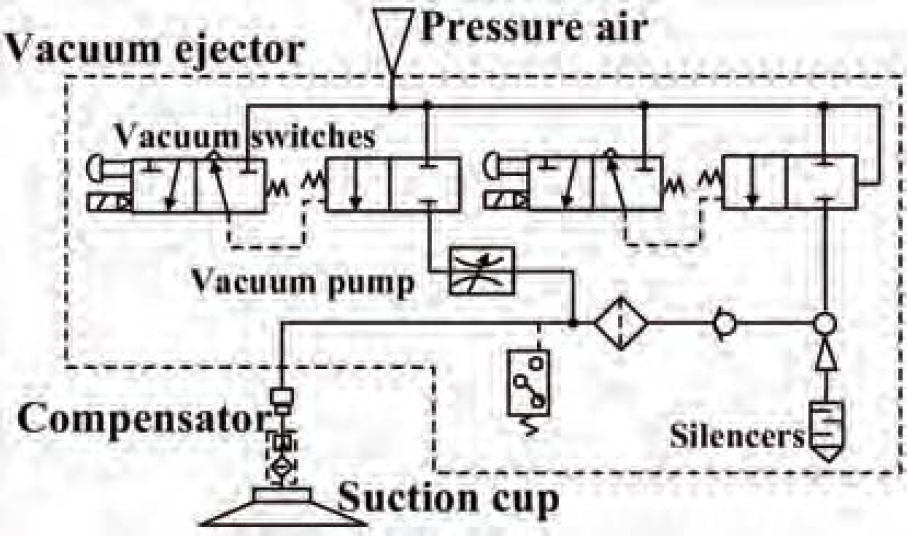
Vacuum ejector
The special layout of the vacuum suckers enables the robot to walk freely in the Y direction without attention to seals. But it is important for the control system to detect obstacles on the surface when the robot moves from one column of glass panes to the next in the right-left direction. Therefore, precise position control of the X cylinder is needed. Many of these systems use the proportional servo valve to drive the cylinders to achieve accurate position control. Unfortunately these valves are not only complicated but also very expensive compared with on-off solenoid valve. Now a lot of researchers (Robert, B. et al., 1997) have tried to use on-off solenoid to realize the position control of pneumatic actuators. Among presented control methods, the pulse width modulation (PWM) has drawn most attentions for its simplicity of hardware construction. However, the benefit of this kind of simple valve is offset by the limitation of the valve response and its discrete on-off nature.
The design of both the X and Y cylinders, to which the vacuum suckers are attached, is cheap, simple and efficient, but the scheme of the X cylinder is even simpler than that of the Y cylinder (shown in Fig. 7). Only one pair of high-speed on-off solenoid valves is used to control the air pressure to the two chambers of the X cylinder. An encoder and a set of gear and rack are used to feedback the position of the piston of the X cylinder. The main reason for this simpler design is that Sky Cleaner 3 mainly moves and cleans along the Y direction, while the movement frequency in the X direction is very low (as shown in Fig. 5).

The scheme of X and Y cylinders
However, the Y cylinder has to raise a load of 25 kg in order to push the cleaning brushes with a friction force when the robot is cleaning downwards from the top of the building. Moreover, the required cleaning efficiency of the robot cannot be met because the high-speed on-off solenoid valves cannot actuate the cylinder fast enough. In order to accelerate the Y cylinder, a larger ordinary 3-position 5-port solenoid valve (Valve 5 in Fig. 7) is used to bypass the high-speed on-off solenoid valves.
Characteristics of the pneumatic cylinders
The major challenge in controlling pneumatic valves is the ability of a control system to deal with hysteresis. This non-linearity is caused by coulombic friction, temperature, and manufacturing tolerance. A closed-loop control system using the pneumatic PWM (Qi. Y. et al., 2003) is often employed in attempting to control solenoid valves. For our robot, the cylinder will move at full speed with 100% high-speed on-off solenoid valve duty on one side, 0% duty on the other side. When the sensors detect window obstacles, usually duties on both sides will change according to the feedback signals. Here the solenoid valves' delay time to open and close is ignored. A duty of 100% means the solenoid valve is fully open; a duty of 0% means it is fully closed.
Firstly, we should discover the characteristics of the nonlinear motion using the PWM algorithm through several experiments.
In Fig.8, PWM duty cycles of 20%, 40%, 60%, 80% and 100% during the Y cylinder going down are displayed. The fastest motion was obtained when the duty was 100%. But the steady-state errors of the different motions were not improved accordingly. Furthermore, the duties below 40% are not strong enough to drive the robot upwards. Fig.9 shows the profiles of the influences of the different pressures on the X cylinder. The fastest motion was obtained when a pressure of 0.75 Mpa was applied to the system. As the pressure dropped, the time to reach the desired position increased.

300mm-position profiles of the Y cylinder going down

100 mm-position profiles of the X cylinder
For the movement of the Y cylinder, only the normal control function is needed. Before the boundary is detected, the cylinder is actuated by an ordinary solenoid valve and two high-speed on-off solenoid valves at the same time and moves at full speed. When the sensor detects the eaves or the ground in the Y direction, the robot should stop immediately. Duties on both sides will become 100% to reduce the speed for a few seconds. Then with a constant PWM duty on driving side (i.e. 50%), 0% on the other side, the cylinder is pushed slowly to the desired position. When the limitation of the position is satisfied, all high-speed on-off solenoid valves are closed to stop the overshoot. During the position control procedure, the ordinary valve is not used to avoid overspeed.
In order to solve the problems of lower stiffness and the nonlinear-movement characteristic of the pneumatic system, a method of segment and variable bang-bang controller is proposed to implement the accurate control of the pneumatic X-cylinder-position servo system (Zhang, H. et al., 2004). Generally, the conventional bang-bang controller for the pneumatic system is described with (1) (2). The control will be over when (2) is satisfied.


Where es is the position error, ε is the limitation to the position error, U1 and U2 are the control signals for the two chambers of the X cylinder and UMAX is the maximum of the control signals. Only the position error is used as the sign to change the control function without considering the factor of velocity. But the velocity of the piston is not zero even if the piston is just on the ideal point. So the movement will not be finished and the control function has to act for the system because of the overshooting, in the end which will cause oscillations of the piston on both sides of the ideal point. Based on this point, an improved variable bang-bang controller is proposed, described with the following (3) and (4). Here ev is the velocity error, C is a constant, sgn () is the signal function and y is the constructor function synthesizing the position and velocity of the piston for movement evaluation. Equation (4) shows that the control signals are computed according to sgn (y).


Fig. 10 shows that there are four areas named  ,
,  ,
,  and
and  which are formed by y and the axes in the phase plane. The control signals will change if the tracking of y changes from
  to
to  or from
  to
to  . Here (5) is satisfied.


The phase plane
The control will be over when (6) is satisfied.

Starting from the beginning of precise position control, the whole process includes two parts:
Firstly, When the tracking of the constructor function moves from
 U1 = UMAX, U2 = 0, the piston will move to the desired position at high speed.
 to
to  :
:
 , the piston will still move towards the ideal point while the piston velocity is decreasing. The following parts are similar. So the position error and the velocity error are approaching zero at the same time because the constructor function is used as evaluation.
Sometimes there are still some oscillations with a small swing even if this method is used. The variable bang-bang controller still controls the high-speed on-off solenoid valves as a kind of 0–1 switch. When the piston is far from the desired position, the movement reaches a very high speed. There is a possibility of movement overshooting because of the control hysteresis. After that, the piston will be pushed back to the ideal point, which will set off the oscillations. On the other hand, the piston may stop before the desired position because of the high friction forces varying with the lubricant condition. Obviously, the friction on the cylinder right after lubrication is smaller than after a long time. At this time the pressure of one chamber will increase, but the other is still open to the air. The piston will begin to move at a high speed once the difference between the pressures in two chambers is great enough to overcome the friction forces. The reason for the high speed is that the static friction force disappears suddenly. So the piston has a possibility to overshoot.
A segment strategy has been devoted to the method of variable bang-bang controller in order to improve the stiffness and eliminate the system nonlinearities. As mentioned before, when the X cylinder is moving to a precise position after finding the obstacles on the glass walls, two different control strategies are needed.
Firstly, when window obstacles are detected, the robot has to begin to adapt while the distance to the obstacles is larger than eb. Here eb is the limitation between the first step and the second step. This phase has been discussed above.
In the second part, the absolute value of es is smaller than eb. The initial pressure will be added to the chambers during this phase. The process is described as below:
IF y≤0, THEN U1 = UMAX (The frequency of the PWM signal is 35Hz), U2 = UMAX − Δu (Δu is the modulation for initial pressure. The frequency of the PWM signal is 15Hz). IF y > 0, THEN U1=UMAX − Δu, U2=UMAX.
Equation (8) is satisfied now.

The chamber which was open to the air is under the initial pressure and the closed valve is actuated by the PWM signal whose frequency is 20Hz. The goal of all the measures is to increase the pressure of the chambers when the piston is close to the desired position. The modulation pressure in the chambers should be suitable so that the system stiffness improves and the sensitivity to non-linearity decreases.
Fig. 11 shows the tracking of position and velocity using the method of segment and variable bang-bang controller. The es and ev approach zero together. It can be seen that the movement is smooth and significantly the maximum velocity is about 680 mm/s. For our pneumatic robotic system, we also tried other control methods such as fuzzy-PID (as shown in Fig. 12) in order to achieve precise control function. Even if the movement is really improved, the velocity and the position error are still not satisfactory based on just using on-off valves.

The position and velocity tracking of the improved bang-bang controller (C=5, 0.65Mpa)

Fuzzy-PID contrastive experiment
Practically, the constructor function can be described with the following (8).

Here parameter C is important. The movement velocity increases and the stability of the control system decreases when C increases. The contrastive experiments are shown in Fig. 13 and 14. In our system, the stability is five.

Contrastive experiment (C=2, 0.65Mpa)

Contrastive experiment (C=8, 0.65Mpa)
The parameter n has an important influence on position control. Like parameter C, the movement velocity will increase considerably while n decreases. At the same time the stability of the control system gradually decreases. Here the parameter n is set as 2. Fig. 15 shows the variety of function y with the changes of n.

The influence of n
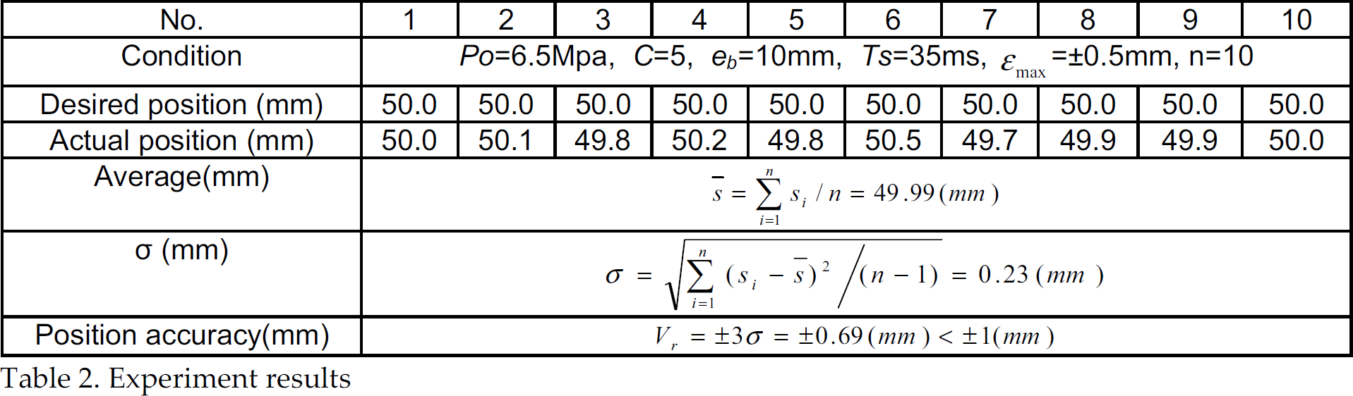
The following Table 2 gives the experimental data for the left and right motion of the robot. It is seen that all of the position errors are within 0.5 mm, which is much better than with the other methods.
Experiment results
A new kind of climbing robot has been built which is used for cleaning the glass walls in Shanghai Science and Technology Museum. Now three sets of robotic systems have been made use on work target. Fig. 16 shows the robot is working on the glass wall of this museum. The applied scheme of X and Y cylinders is employed to drive the high-speed solenoid valves and an ordinary solenoid valve to adjust the air-flow and pressure to the cylinders, so that the construction of the pneumatic system is simple and efficient. In order to solve the problems of lower stiffness and the nonlinear movement characteristic of a pneumatic system, a method of segment and variable bang-bang controller is proposed to implement the accurate control of position servo system. Testing results show that the controller can effectively improve the control quality.

Sky Cleaner 3 cleaning on the target glass wall