
Abstract
This paper presents a grouser developed for the wheels of lunar exploration rovers to measure sinkage. The wheels, which are intended to traverse loose soil such as lunar regolith, contain grousers that transfer thrust to the wheels and thus to the body of the rover. The interaction between the wheel (with grousers) and the loose soil can be described using a kinematic model. When traversing loose soil, the wheel sinks into the soil, which necessitates knowledge of the entrance angle needed in order to avoid this problem. If the entrance angle is known, the sinkage can be measured in real time before adverse conditions occur. Because of the importance and usefulness of detecting the entrance angle of the wheel, we herein propose a grouser with an embedded tactile sensor. A strain gauge on the surface of the grousers serves as the tactile sensor. In order to confirm the precision of the proposed grouser, we have performed tests on a rigid surface and loose soil surfaces.
1. Introduction
Robots are among the most important mission systems for planetary exploration. These robots are designed to travel along planetary surfaces to gather precise information regarding, among other things, the origin of the solar system [1]. The NASA Mars mission in 1997 utilized the micro robot Sojourner, which moved about and explored the surface of the planet, transmitting important data and detailed images of the Martian surface back to Earth [2]. The Sojourner mission demonstrated the importance of mobile exploration. In 2003, NASA/JPL sent Mars Exploration Rover (MER) to Mars (Figure 1), which also transmitted important data [3]. Planetary exploration rovers are required to traverse rough terrain such as in craters and cliffs, which are scientifically important locations for exploration. Furthermore, rovers travelling over rough terrain must avoid tipping over and becoming stuck. The surface of the Moon, which is the subject of this study, is covered with regolith that is soft and slippery. This regolith, which is made up of fragments of rock broken from the moon and other celestial bodies, undergoes chemical changes caused by the granule phenomenon. As this regolith is different from weathering soil on Earth, a conventional wheel would not achieve the necessary traction efficiency for movement on this surface. In addition, the lunar environment is a vacuum and is exposed to radiation from space. Moreover, the temperature differences between day and night are intense. In such environments, conventional tires meant for use on Earth cannot be used. Therefore, wheels made of a rigid material, such as metal, are used for lunar and Mars rovers. However, when a rover with rigid wheels traverses loose soil, there is a possibility of degrading traction conditions. This means that slipping and sinking behaviours can occur. Figure 2 shows the MER during a test meant to simulate the Martian surface. The wheels of the MER can be seen sinking into the soil so they cannot move, which is a situation that is not easily rectified.
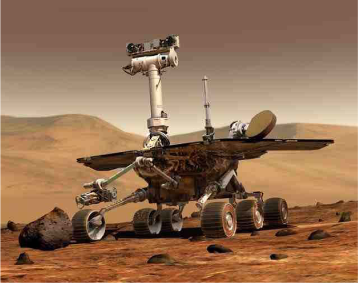
Mar Exploration Rover (NASA/JPL) [3]

NASA/JPL experiment on earth meant to simulate the Martian surface [3]
When the rovers are traversing loose soil, we have to consider the conditions under the wheels. The relation between the wheel and loose soil can be described using terramechanics [4]. Using terramechanics, the entrance angle, which can indicate the depth that the wheel is sinking into the soil, is used to lead the drawbar pull. Studies on terramechanics have been done by some researchers [5]-[8]; Ding et al. summarized the most recent work in the area [9]. It is necessary to understand the range of the contacting angle between the wheel and loose soil for the derivation of drawbar pull. The contacting angle is shown using the entrance angle and the leaving angle. If the entrance angle can be detected while the rovers are traversing, the drawbar pull and the sinkage can be derived in “real time”. It is effective to detect sinkage to determine the rover's moving path. Moreover, the poor traction conditions can be avoided if the entrance angle is known while the rovers are traversing loose soil. Some research has been performed to give the range of contacting angle between the wheel and loose soil. Krebs et al. developed a flexible wheel with tactile sensors [10]. They used IR distance sensors to detect the contact angle between the flexible wheel and the ground. Nagatani et al. developed a wheel with a built-in force sensor array (containing many sensors on the surface of the wheel) that can measure the normal stress distribution [11]. This study focused on the grousers installed on the surface of the wheels. The grousers first come into with loose soil during traversing, and they give large resistance compared with the force of the vertical load. Therefore, it is useful to know the resistance of grousers to detect the entrance angle.
In this paper, we present a developed wheel with grousers with tactile sensors to determine the entrance angle. In section 2, sinkage of the wheel with grousers is explained. In section 3, the development of a grouser with a tactile sensor is explained. The experiments and results are presented in section 4. Finally, the conclusions of the study are described in section 5.
2. Sinkage of wheel with grousers
The wheels on rovers are installed with grousers to achieve an effective driving force on loose soil. Ding et al. studied the influence of grousers experimentally [12][13].
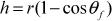
Figure 3 shows the interaction between the wheel with grousers and loose soil in static condition. The entrance angle θf is changed due to the presence of grousers. If the wheel does not contain grousers, the sinkage is written as follows:

Interaction between wheel with grousers and loose soil
On the other hand, if the wheel contains grousers on its surface, the sinkage is written as follows:
Figure 4 shows a dynamic condition of sinkage of the wheel. If the wheel has a rotation movement on loose soil, the sinkage of the wheel increases gradually. If we can obtain the value of sinkage during realistic operation, we can prevent the wheel from becoming stuck. When the wheel is rotating on loose soil, the grouser mounted on the surface of the wheel comes into contact with loose soil. If the values of the wheel radius, r, the length of the grouser, l, and θ f are known, we can predict sinkage, h, in real time. If the grouser touches the surface of the soil, we can obtain the entrance angle θ f . The grouser with the incorporated tactile sensor is described in the following section.

Dynamic condition of sinkage of wheel
3. Development of grousers with incorporated tactile sensor
3.1 Grousers mounted with tactile sensor
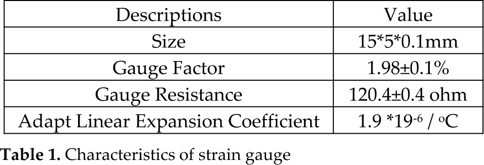
We previously mentioned the advantages of the ability of a grouser to detect contact. Figure 5 shows a strain gauge that is installed on the surface of the grouser. The strain gauge resistance value changes when the strain gauge is warped, and we can convert this resistance value (voltage) to a strain value. Table 1 shows the characteristics of the installed strain gauge [14], and Figure 6 shows the grouser with the strain gauge. The strain gauge is installed in the centre of the grouser surface in the shearing direction.
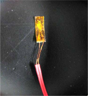
Strain gauge mounted to the grouser acting as a tactile sensor [12]
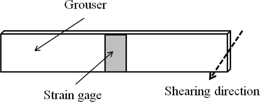
Mounted position of strain gauge
Characteristics of strain gauge
3.2 Wheel with grousers
The diameter of the wheel on which the grousers are installed is 200 mm and the width is 100 mm. The wheel, which is made from acrylic resin, contains 12 grousers spaced at 30-degree intervals. A dsPIC(dsPIC33FJ128MC204) microcontroller unit performs analogue-to-digital conversions used to process the data from the strain gauge, and is shown in Figure 7. An overview of the wheel with the installed devices is shown in Figure 8. The grousers are installed on the surface of the wheel, and the dsPIC unit is integrated into the wheel hub. A low pass filter (LPF) is used on the raw strain data, and the cutoff frequency determined using a data logger (which was used throughout the experiment to measure strain) [14]. From these measurements, we set the cutoff frequency to 1 kHz.

Overview of dsPIC universal board for sensor data acquisition
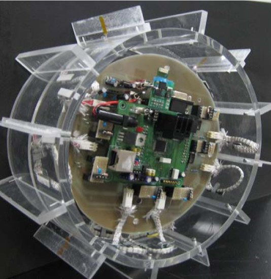
Wheel with onboard microcontroller (dsPIC) and grousers with a tactile sensor
3.3 Measurement procedure
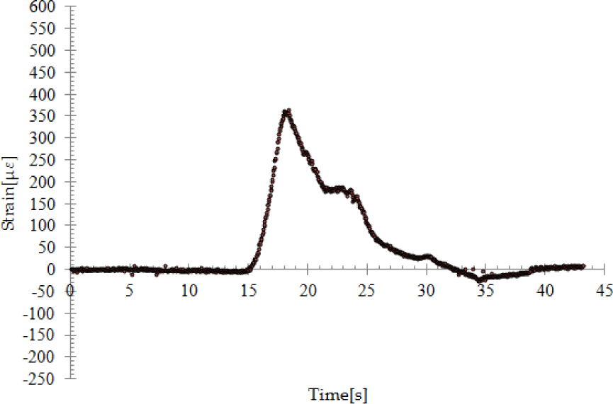
Figure 9 shows the overall system used to measure the value of the strain gauge. First, the value of strain is given by the tactile sensor installed on the grouser when the wheel is rotating. The signal is then amplified and low pass filtered, then sent to the A/D converter. After conversion, the signal is sent to the dsPIC unit, which sends data to the PC using a wireless BluetoothR unit. Figure 10 shows the strain gauge data without low pass filter. The value of the strain peaks around 20 s for all data, indicating that the grouser touches the obstacle at that point. However, it is difficult to distinguish the exact location of contact from the unfiltered data in Figure 10. Therefore, we use a low pass filter to remove high frequency noise (shown in Figure 11), from which we can determine the point of contact with some obstacle.

Measurement procedure

Strain data without LPF
Strain data with LPF
3.4 Preliminary experiment to determine contact point
Preliminary experiments are performed using a rigid surface of a known height, h‘, as shown in Figure 12. For comparison, the distance from the ground to the centre axis of the wheel is set as the reference position. When the grouser touches the obstacle, we obtain strain gauge data from the dsPIC unit. Here, we must define the momentary point when the grouser touches the obstacle. Since the value of motor current becomes large when the motor experiences a larger load, we can use motor current to determine when the grouser makes contact. Here, we focus on only one grouser; however, if the wheel traverses ground, the current data contains data from various loads because there are many grousers installed on the surface of the wheel. For this experiment, however, the wheel is suspended such that only one grouser touches the obstacle. At this time, the value of current of the motor becomes large. We can check the value of strain at the same time to identify a correlation. Figure 13 shows the relation between the value of current and the value of strain. We observe that the relationship between strain and motor current is linear. The effectiveness of using the value of strain is thus confirmed. Therefore we can use the notion of momentary point (contact point of the obstacle) as shown in Figure 14. Moreover, the sampling frequency can be made lower because it is easy to determine the contact point of some obstacle. After the value of strain is given, the angular position of the wheel is detected using the motor encoder. We predict the sinkage from this wheel angular position.

Conditions for preliminary experiment
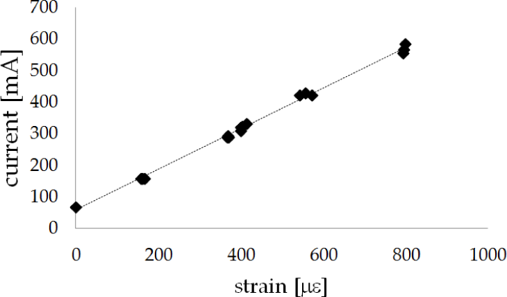
Linear relationship between strain and motor current

Strain data: contact point is determined using this data.
For this, we use eq. (3) as follows:

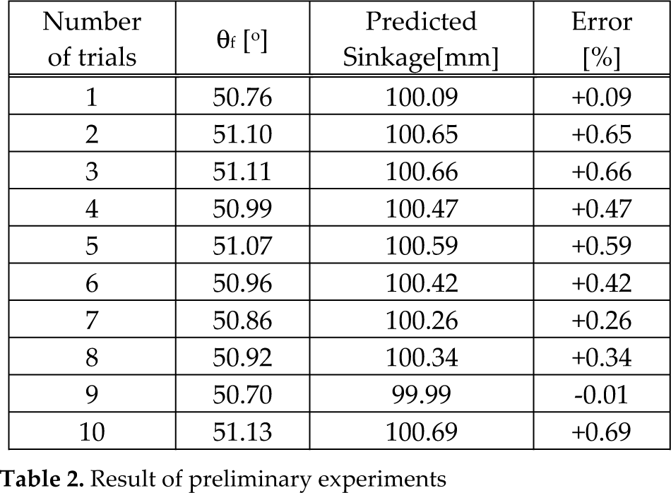
Table 2 shows the results of the ten preliminary experiments, in which the obstacle height was 100mm. The error in the experiment is within ±0.7% for all results, indicating a high precision. From these results, we can see that the technique developed herein is effective at predicting the extent of sinkage. The next section describes an experiment on loose soil.
Result of preliminary experiments
4. Loose soil experiment
4.1 Experimental procedure
Figure 15 shows the single-wheel experimental testbed. The experimental system's mechanical parts and sensors, which connect the wheel with a tactile sensor to measure sinkage, are shown in Figure 16. A single wheel, a parallel link, a stator, a guide rail, and a load balancer were used in carrying out various experiments. A parallel link is attached between the axis of the wheel and the load balancer. We control the rotation of the wheel and measure angular position using the wheel's motor encoder. The contact angle of the grouser against the loose soil is determined from the value of the strain gauge. Figure 17 shows the experimental procedure. The default position of the grouser is first defined using the reference position. The testbed controller then initiates wheel rotation, and then the wheel touches the loose soil and the value of the grouser's contact angle is measured. From these values, we estimate the sinkage depth. The actual sinkage value is calculated by the date given from the rotary encoder (as shown in Figure 16) installed onto the axis of the parallel link. The predicted sinkage value can then be compared with the actual value. Although the wheel has 12 grousers, each with a tactile sensor, we focus here on only one grouser. The experimental parameters are shown in Table 3.

Overview of single wheel testbed
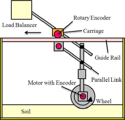
Configuration of single wheel testbed

Experimental procedure
Experimental parameters

4.2 Results and discussion
Table 4 shows the experimental results, including the detected entrance angle, θ f , predicted sinkage and error between predicted sinkage and actual sinkage. The error is within 2%, except for the sixth trial. Although the error of this experiment is small, it is quite large compared with the rigid surface case. This indicates that the resistance is small because of the soft surface of the loose soil. An error of ± 2% corresponds to about 0.5 mm of sinkage; therefore, the wheel is able to obtain sinkage information before it becomes stuck in the loose soil. Furthermore, an error as large as 8% corresponds to only about 2 mm, which is very small. Therefore, the proposed grouser with a tactile sensor is effective at determining the sinkage of the wheel in real time. We must consider the difference between the cases of rigid and soft surfaces. In the case of a rigid surface, the surface conditions are non-varying or not easily changed. On the other hand, in the case of a soft surface, the surface conditions may change very easily. This means that it is difficult to obtain the same default condition every time. Therefore, we predict the general situation, as in Figure 18. Since the surface of loose soil is variable and is not the same at every time step, we assume that the difference in strain is small. However, since the locomotion velocity of a lunar rover wheel is typically very slow (e.g., 1 cm/s), the proposed grouser is sufficiently effective to prevent poor traction conditions.
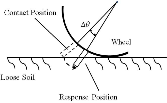
Predicted interaction between grouser and loose soil
Experimental results in loose soil case

5. Conclusion
In this paper, we proposed a grouser with an incorporated strain gauge, which acts as a tactile sensor. A dsPIC microcontroller unit was used to process data from the strain gauge. Several experiments verified that the values obtained from the grouser with an embedded tactile sensor were very accurate. Furthermore, the sinkage values predicted using the tactile sensor were very close to the actual sinkage values, indicating that the rover would be able to prevent poor traction conditions (especially over-sinkage of the wheels).
This wheel considered contains 12 grousers fitted with tactile sensors. The wheel is therefore able to obtain a multitude of strain values, which enables various future studies, e.g., a multi-grouser model (measurement of reaction force from soil). We plan to engage these avenues of study in the near future.
We assume this type of grouser with a built-in tactile sensor will be necessary for high-performance lunar rovers.
6. Acknowledgement
This work was supported by KAKENHI (23760223).