
Abstract
A passive linkage mechanism is used for increasing the mobile performance of a wheeled vehicle on uneven ground. The mechanism changes its shape according to the terrain and enables all the wheels to remain grounded while the vehicle operates over rough terrain. This means that the shape of the passive linkage mechanism must correspond to that of the terrain surface, so that the vehicle can estimate the shape of the surface while passing over it. This paper proposes a new terrain-surface estimation scheme that uses a passive linkage mechanism. Our key concept is to enable changes in the vehicle body's configuration to correspond to those in the terrain's shape. Using this concept, our mobile platform estimates the shape of terrain surfaces without using external sensors; the estimated surface shapes are used to adjust the reference velocities of individual wheels, thereby improving the mobile performance of the vehicle. We test our proposed scheme by experiments using a prototype vehicle.
Keywords
1. Introduction
Mobile robot technologies are expected to perform various tasks in structured environments, such as nuclear power plants, large factories, nursing care facilities, hospitals and homes. However, such indoor environments contain narrow spaces with steps and slopes, making it difficult for generic car-like vehicles to operate.
Generally, a vehicle must possess quick and efficient mobile functionality to execute tasks effectively. Omnidirectional mobility can be helpful, especially in narrow spaces, because no holonomic constraints are imposed on vehicle motion [1–2]. Furthermore, a step-overcoming function is necessary wherever the vehicle passes through an environment that has vertical gaps between two or more flat surfaces. Therefore, to operate in such a general environment, a vehicle needs to be equipped with two functions. In previous studies, various omnidirectional mobile systems with step-overcoming functions, including omni-wheeled robots, active caster robots, legged robots, ball-shaped wheel robots and crawler robots, have been proposed. Omnidirectional wheeled vehicles [3–4] with special wheels are widely used. However, the special wheels consist of small rollers whose radii limit step-climbing performance. Thus, this type of robot can only pass over small gaps. To improve performance the wheel diameters should be large [4], but it is difficult to design large-wheeled vehicles for practical use. Robots with active casters are also widely used [5]; however, the caster mechanism is complex and requires redundant actuators: one for generating traction force and the other for coordinating its rudder. The legged robot [6–7] can move in all directions and pass over rough terrain. However, its energy efficiency is low because the mechanisms tend to be complicated; for example, the robot needs to use its actuators just to maintain its posture. Robots with ball-shaped wheels can move in all directions [8]; however, they cannot operate on rough ground. A special crawler mechanism [9] has also been proposed for omnidirectional mobile robots, but these robots can only climb over small steps. In summary, we still lack a mobile system that is well adapted to both narrow spaces and irregular terrains.
Therefore, we are developing a holonomic omnidirectional vehicle with step-climbing ability [10]. Our prototype utilizes a new passive linkage mechanism that is suitable for steps in a structured environment; the vehicle has seven special wheels with actuators. To realize high mobility during step climbing, our vehicle drives all its wheels to increase the traction force. For practical use, it is important that vehicle mechanisms are not overdesigned. Generally, for operations on structured terrain, the energy efficiency of a wheeled mobile system is better than that of other mobile mechanisms [11]. Thus, we adopt special wheels for the omnidirectional mobile function. These special universal wheels realize omnidirectional mobility with the advantages of a wheeled system [12].
To improve the step-climbing ability of a robot, there are two design approaches. One is to improve the step-climbing ability equally in all directions, and the other is to use a simple mechanism and improve the ability to pass over steps only in one or two directions. If the robot has both holonomic and omnidirectional mobile abilities, it can change its direction in front of a step. Therefore, and to realize a low-cost system, we designed a holonomic omnidirectional wheeled robot that passes over steps only in the forward and backward directions.
To increase the mobile performance of a wheeled vehicle with a passive linkage mechanism, it is important to be able to estimate the terrain-surface shape. This is because, when a vehicle with a passive linkage mechanism operates on uneven ground, the velocities of the wheels differ from one another because the angular relationships between each wheel and the ground differ. Therefore, we must be able to modify the wheel control reference according to the terrain-surface shape. An unsuitable control reference that does not consider the terrain-surface shape will cause the wheels to slip or to rotate improperly, thus degrading mobile performance of the vehicle.
In previous research, many surface-estimating schemes have been developed. One widely-used approach involves external sensors on the vehicle to estimate ground shape. Usually, the sensors include CCD cameras [13–15] or laser rangefinders [16–17]. Alternatively, Strelow [18] has proposed the use of odometry for rough terrain; in this approach, parameters describing the ground and wheels are derived beforehand and no external sensors are required. However, all the previous approaches require either redundant external sensors or accurate ground-wheel information, and therefore they are not generally suitable for practical use.
In contrast, our vehicle uses passive linkages to change its body configuration along a terrain surface. This means that the body configuration itself reflects the underlying ground surface, so the vehicle can use information about its own configuration to estimate the terrain surface. Many mobile vehicles have been developed using passive linkage mechanisms [19–21], e.g., the rocker-bogie suspension system [21]. However, most of them do not use changes in body configurations to adjust the control reference. Lamon et al. have discussed the body configuration for 3D-odometry [22]; however, they do not consider a kinematic model or the velocity of a control reference for each wheel.
Therefore, we propose a terrain-surface estimation scheme based on information about the vehicle's body configuration, and use that scheme in an attempt to improve the mobile performance of the vehicle. Specifically, our proposed scheme estimates the nature of ground surfaces using only internal sensors that are integral to the vehicle's body.
The rest of this paper is organized as follows. We introduce the mechanical design of the vehicle and its controller in Section 2. In Section 3, we describe our novel terrain-surface estimation scheme. In Section 4, we discuss our wheel control scheme, which distributes the load when the vehicle passes over a step. Section 5 contains our experimental results. Conclusions are drawn in Section 6.
2. Mobile Platform
2.1 Mobile Mechanism
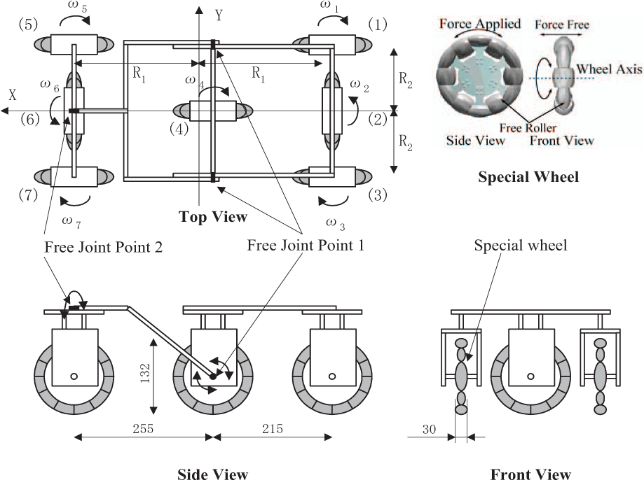
Figure 1 shows the prototype vehicle system. The vehicle has seven wheels, with each wheel connected to a single DC motor. The dimensions of the prototype vehicle are 750 mm (L) × 540 mm (W) × 520 mm (H), and its weight is 22 kg.

Our Prototype: (1) is the passive joint 1 (pitch angle), (2) is the passive joint 2 (roll angle), (3) is the special wheel, and (4) is the control computer system (CPU and I/O card)
The mobile mechanism consists of seven special wheels with free rollers and a passive linkage system. Each special wheel consists of 12 cylindrical free-rollers [23] and generates omnidirectional motion using multiple wheels arranged in different directions under suitable wheel control (Fig. 2).
Overview of the proposed mechanism
Our mechanism utilizes a new passive linkage system, which is more suitable for climbing steps than general rocker-bogie suspensions [19], as shown in Fig. 3 [24]. The free joint at point 1 is at the same height as the axle, which helps the vehicle pass over a step smoothly when the wheel makes contact with it (Fig. 4). No sensors or additional actuators are needed to pass over irregular terrain.

New passive linkage mechanism
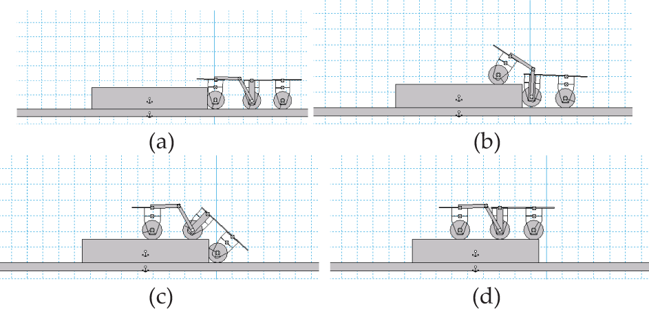
Step climbing with the proposed vehicle
2.2 Controller
The control system is shown in Fig. 5. Our vehicle has seven driver motors, two potentiometers at each joint for the configuration angle, and two tilt meters for the inclination of the body. The vehicle has a redundant actuation system using seven wheels; a PID-based control system [22] synchronizes the wheels' rotation on the basis of a control reference, which is calculated from a kinematic model.

Our vehicle control system
3. Terrain-surface Estimation
3.1 Kinematics of Passive Linkages
Our vehicle has a passive linkage mechanism in its body, such that the body configuration changes according to the terrain condition as the vehicle passes over a step (Fig. 4). Therefore, when climbing a step, the vector of the direction of travel of each wheel must be modified by referring to the configuration of the linkage mechanism.
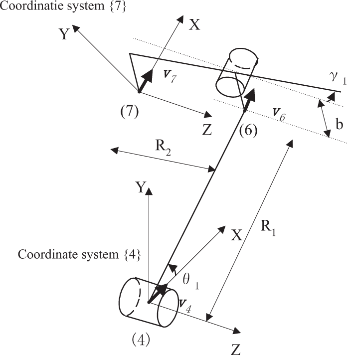
Let us consider the relationship between the rotational velocity vector of each wheel and the change in the body configuration for a general, passive linkage vehicle model. We assume that the vehicle has n passive linkages, with all wheels grounded and actuated. When the vehicle passes over a barrier, as shown in Fig. 6, the velocity vector of wheel i + 1 is calculated from (1) using the velocity vector of wheel i and the rotational velocity vector of wheel i + 1. These vectors are three-dimensional, and each is expressed in its local coordinate system:

Here, i is the number of a wheel (i = l⋯n);
i

Passive linkage model
3.2 Adaptation to the Wheel
The velocity vector of a wheel has the following features:
Its direction is the same as the driving direction of the wheel. Its direction is perpendicular to the terrain surface when the wheel is grounded.
In consideration of these conditions, we define the coordinate system of each wheel as shown in Fig. 7.

Definition of the coordinate system of the wheel
The travelling distance of a wheel is obtained from the velocity of the driving-direction component and the rotation of the linkage to which the wheel is connected. Therefore, using this definition, the x-component of the velocity vector and the rotational vector toward the z-axis in coordinate system {i} yield the travelling distance. The value of the travelling distance for wheel i + 1 (ωi+1) is derived from (2) and (3):


In (2), ‖i+1
The passive body linkage mechanism is designed such that all the wheels are grounded; therefore, we can assume that each wheel contacts the plane. When the angle between the x-axis of coordinate {i} and that of coordinate {i + 1} is αi, the transformation matrix is given by (5). The angle αi must obey (6) because the wheel is always grounded to the terrain on which it moves. In (6), ‖i+1


3.3 Adaptation to our Prototype
In 4 3.2, we discussed the vehicle kinematics and travelling distance of the wheels with reference to the body configuration. Now, we adapt the proposed derivation scheme to our prototype vehicle. Our vehicle uses its attitude sensors to measure changes in body configuration and then uses this information to derive the travelling distances of the wheels.
Our prototype vehicle is the two-linkage model shown in Fig. 8. The vehicle has two free joints, and each joint is fitted with potentiometers. Tilt sensors are attached to the rear part of the vehicle body. With these sensors, we can measure the following angles:
The roll angle θ1 and the pitch angle γ1 of the body are obtained from the potentiometers. The roll angle θ2 and the pitch angle γ2 of the body inclination are obtained from the tilt sensors.

Angle meters from (a) the front and (b) the side views of the vehicle
Our vehicle has seven wheels, all of which are actuated. Figure 2 identifies the wheel numbers
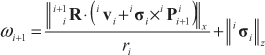
Coordinate systems and parameters
When the vehicle moves at v0 in the x-direction of coordinate system {4}, the velocity vector of wheel 7 in the coordinate system {4} is given by:

Similarly, the velocities of wheels 1, 3 and 5 are obtained from:


The rotational vector of each body linkage is derived using the roll and pitch angles, as shown in (11) and (12):


Linkages 5 and 7 form the same rigid body; therefore, 4

Since the x-axis is defined in the drive direction of the wheel and the velocity vector is parallel to the drive direction as in (6), the angle

Equations (13)–(15) allow us to determine the travelling distance of all wheels on the basis of wheel 4 alone.
Because our vehicle can pass over obstacles only in the forward and backward directions, our vehicle uses the travelling distance of wheel 7 based on wheel 4 in the forward direction and that of wheel 3 in the backward direction for terrain-surface estimation. Our estimation scheme assumes that the radii of all the wheels remain constant because our vehicle uses special wheels composed of a urethane rubber, so their diameters remain constant.
4. Coordination of Wheel Control
In § 3, we discussed the travelling distance of wheels with reference to the body configuration on our prototype. This means that even if the vehicle passes over an obstacle with a constant speed, each wheel should change its rotational velocity according to the body configuration. Any unsuitable rotational velocity of a wheel that does not consider the change in body configuration in response to changes in the terrain surface will cause the wheel to slip, thus decreasing the accuracy of the terrain estimation.
In general, a mobile vehicle for rough terrain uses a traction control scheme to control the wheels [25]. In previous studies, we discussed a wheel feedback control system based on the output traction of each wheel [26]. However, it is difficult to coordinate the rotational velocities of all the wheels using only traction control, especially when the changes in the body configuration are large. Therefore, in the vehicle described here, we coordinate the wheel control reference on the basis of the terrain-surface shape, as estimated from (7)–(14).
The velocity vectors for each wheel are only calculated from the kinematic relationships for the wheels, so the balance between the absolute values of each vector should be maintained when the vehicle passes over uneven ground. However, in many cases these values can increase when changes in the body configuration are large; thus, if we simply use (7)–(14) to obtain the wheel control reference from these large vectors, the wheel control references can become so large that the driver motors cannot realize them. As a result, the vehicle cannot maintain balance among the wheel rotational velocities, causing the wheels to slip and thus reducing the accuracy of the terrain-surface estimates. Therefore, to obtain suitable wheel control references on the basis of changes in the body configuration according to the terrain surface, we consider the following points:
When the vehicle passes over a step at V0 in the forward direction of the vehicle coordinate system, as shown in Fig. 2, we set V0 to the velocity in the x-direction in the coordinate system {4}. To maintain balance among the wheels' rotational velocities, all the wheel velocities based on V0 referring to the body configuration must be smaller than V0.
The important result of this scheme is that none of the references exceed V0, and so they cannot have extraordinarily large values. This ensures that each driver motor can realize the reference value for each wheel and that the balance among wheel velocities is maintained.
Now, we explain this idea in more detail. Our proposed scheme is shown in Fig. 10. When the vehicle passes over a step at velocity V0 in the vehicle coordinate system - as shown in Fig. 2 - we temporarily set the x-component of the velocity in coordinate system {4} to V0, as follows:

Next, we derive the velocity vectors of all the wheels using (7)–(10). The coefficient Ci of wheel i is determined by:
where 4

where c = min{c1,⋯,c7}.

Flowchart of the wheel control reference calculation
5. Experiment
5.1 Experimental Setup
We tested the performance of our terrain-surface estimation scheme by using our prototype vehicle in experiments. The vehicle parameters are shown in Table 1. In this experiment, the prototype vehicle passed over a step in the forward direction at a fixed velocity, as illustrated in Fig. 11(a). The height of the step was 30 mm in the first case and 60 mm in the second, as in Fig. 11(b). The ground surface and the step were made of styrene foam. The static friction coefficient between the styrene foam and the wheel rubber was 0.4, and the dynamic coefficient was 0.3. In both cases, the vehicle velocity V0 was 0.25 m/s or 0.5 m/s. The vehicle started moving from the start position in Fig. 11(b), and moved at a fixed reference velocity V0 as it passed over the step. During this step-climbing test, the wheel velocity references were obtained from (17) and the PID-based controller distributed any large loads that would have been applied to the wheel in contact with the step [26].
Vehicle parameters

Experimental setup
We tested the four cases listed in Table 2. To verify that our proposed system is effective, the results from it are compared with those from a standard system that uses only the travelling distance of wheel 4 and the roll angle θ2 of the vehicle body. This standard scheme is normally used for a wheeled vehicle and does not consider any change in body shape.
Experimental conditions for each case

5.2 Experimental Results
Figure 12 shows the motion of our prototype vehicle as it passed over the step. The white points indicate the vehicle position (specifically, the position of the passive joint 1 in Fig. 1) at 0.3 s intervals. Figure 12 suggests that the vehicle with our proposed terrain-surface estimation scheme reduces wheel slippage and passes the gap more smoothly than when controlled by the standard scheme.

Passing over a 60 mm-high step (Case 2b)
Figure 13 shows the generated wheel control references as it passed over the step. Fig. 13(b) is the calculated value derived by reflecting the body configuration simply. In this case, the references are derived based on the middle wheel (i = 4), and they are sometimes extraordinary values when the body configuration changes significantly. The maximum speed of the prototype is 0.8 m/s; thus, it cannot realize these references. Fig. 13(a) is the finally-applied reference for when the vehicle passed the step using the proposed coordination scheme in § 4. Using this idea, the reference values are calculated within the range of V0 (= 0.5 m/s).

Control references as the vehicle passes over a 60 mm-high step (Case 2b)
In general, wheel slippage reduces the mobile performance of wheeled vehicles and degrades the accuracy of estimates for the terrain surface. Thus, we evaluate the wheel slippage that occurred in this experiment. Figure 14 shows the slippage ratios for the middle wheel (i = 4); these slip ratios were calculated by [26]:

Here, ωi is the rotational speed of the wheel, ri is the wheel radius and vi. is the vehicle speed. Figure 14 shows three peaks in slippage during step climbing. The first peak occurred when the front wheels were in contact with the step; the second peak occurred when the middle wheel was in contact; and the third peak corresponded to contact by the rear wheels.

Slippage ratios as the vehicle passes over the step
Figure 14 shows that if the step height increases then the wheel slippage also increases. This means that a higher step requires more traction force for passing over it and that wheel slippage also increases. Furthermore, when the vehicle velocity increases, wheel slippage also increases. When the vehicle speed increases, the speed of body configuration changes also increases. If the vehicle uses a fixed-velocity reference, the difference from the required velocity - which is derived from a kinematic relationship between the terrain surface and the vehicle body - will be large, which will cause the wheels to slip. From these considerations, we can identify two causes of wheel slippage: increases in the required traction force and large differences in unsuitable velocity references.
Figure 14 also shows that, in all cases, wheel slippage was reduced by utilizing our proposed scheme. This verifies that our proposed scheme improves the mobile performance of the wheeled vehicle with a passive linkage mechanism. Furthermore, peaks in wheel slippage were reduced with our scheme, especially in high-speed cases; this means that the velocity reference coordination based on the body shape works well.
Figures 15 and 16 show results from the terrain-surface estimation. These figures show that our vehicle can estimate the shape of a step. In Fig. 15, the estimated vertical surface is inclined because of wheel slippage; this is especially true for the standard method, which has larger wheel slippage as in Fig. 14(a). In contrast, estimation results with our proposed scheme are more accurate than those from the standard method. Figure 15(b) shows the same tendencies as Fig. 15(a). However, the estimated results at 0.25 m/s (Fig. 15(a)) are more accurate than those at 0.5 m/s (Fig. 15(b)). This is because, at high speeds, wheels slip more easily, and the vehicle body is shaken more in response to changes in terrain. When the vehicle passes over the 60 mm step, as in Fig. 16, the same tendencies are apparent. However, the wheel slippage and body vibrations are larger than those encountered with the 30 mm step (Fig. 15).

Comparisons of surface estimation results for a 30 mm-high step

Comparisons of estimation results for a 60 mm-high step
These results show that wheel slippage contributes to errors in terrain-surface estimates; therefore, we evaluate the relationship between them. Figure 17 shows the integration of the absolute value of the estimation error and the slippage distance during one trial. Using our proposed scheme, the wheel slippage and estimation error are reduced compared to values from the standard scheme. Furthermore, with our proposed scheme, wheel slippage and estimation errors are almost the same, indicating that the cause of estimation errors is largely wheel slippage. However, with the standard scheme wheel slippage differs from the estimation error. This means that the estimation error in the standard scheme includes errors from not only wheel slippage but also from changes in body configuration when the vehicle passes over a step.

Relationships between wheel slippage and surface estimation errors for the 60 mm step
From these discussions, our proposed scheme presents two advantages:
Wheel slippage is reduced. This improves the mobile performance of the vehicle as well as the accuracy of the estimates for terrain surfaces. The estimates of terrain surfaces are more accurate because changes in body configuration are taken into account.
5.3 Terrain Estimation in a Real Environment
To verify the practical performance of our terrain-surface estimation scheme, we tested it in the outdoor environment shown in Fig. 18(a). Our prototype vehicle passed over 10 steps, each having a height of 110 mm, at a velocity of 0.25 m/s (Fig. 18(b)). The estimated terrain shapes are compared with the actual shapes in Fig. 19. The comparison in this figure confirms that our vehicle reliably estimates the terrain-surface shape.

Terrain-surface estimations in an outdoor environment

Surface estimation results for passage over 10 steps
Using our scheme, the vehicle traversed the test path. This is noteworthy because the height of each step (110 mm) was almost the same as the diameter of each wheel. In such situations, it is difficult for wheeled vehicles to pass [3]; in fact, a vehicle without our proposed scheme would not be able to pass over it because of wheel slippage. From this result, our proposed scheme can estimate the shapes of a terrain surface and thereby increase the mobile performance of the vehicle.
Note that the estimated results in Fig. 19 have some unevenness because the step surfaces were uneven. The estimation errors were accumulated at the end of this experiment; the maximum estimation errors were 66 mm in height and 134 mm in distance travelled. Nevertheless, the shape of the terrain surface was sufficiently accurate to reduce wheel slippage and enable the vehicle to climb the steps.
5.4 Extension to Odometry
To further test the practical effectiveness of our system, we adapted our proposed scheme to omnidirectional movement. For this test, our vehicle used its omnidirectional mobile function to traverse the reference track shown in Fig. 20. At a point on the track, the vehicle encountered a 60 mm-high step.

Reference track for tests of omnidirectional motion
Figure 21 shows photographs of our prototype vehicle negotiating the track. As the vehicle passes over the step, its body configuration changes. Figure 22 shows the odometry results for completing the track. Using our proposed scheme, the shape of the step was estimated. The position estimation errors at the goal point were 18 mm along the x-axis, 37 mm along the y-axis, and 7 mm along the z-axis. These estimation errors are less than the radius of any one wheel. Considering the shape of this terrain surface, we conclude that our system has the potential for realizing odometry on uneven ground.

Motion of our prototype on the reference track
Trajectory of our vehicle around the reference track
6. Conclusion
In this paper, we propose a new terrain-surface estimation scheme for wheeled vehicles operating on uneven ground. The scheme uses information about changes in body configuration on a vehicle equipped with a passive linkage mechanism. Our approach provides terrain-surface estimates using only internal sensors on the vehicle body. Experiments using a prototype vehicle showed that our proposed scheme offers the following advantages:
By using a suitable control reference for each wheel to account for changes in body configuration, our proposed scheme reduces wheel slippage. As a result, both the mobile performance of the vehicle and the accuracy of terrain-surface estimates are improved. By considering changes in the body configuration, the accuracy of the terrain-surface estimates is improved.
In the future, we intend to test our scheme not only in structured environments containing simple vertical gaps but also in outdoor environments with irregular changes in elevation.