
Abstract
In this paper, we present a new indoor 'simultaneous localization and mapping‘ (SLAM) technique based on an upward-looking ceiling camera. Adapted from our previous work [17], the proposed method employs sparsely-distributed line and point landmarks in an indoor environment to aid with data association and reduce extended Kalman filter computation as compared with earlier techniques. Further, the proposed method exploits geometric relationships between the two types of landmarks to provide added information about the environment. This geometric information is measured with an upward-looking ceiling camera and is used as a constraint in Kalman filtering. The performance of the proposed ceiling-view (CV) SLAM is demonstrated through simulations and experiments. The proposed method performs localization and mapping more accurately than those methods that use the two types of landmarks without taking into account their relative geometries.
Keywords
1. Introduction
Since the inception of simultaneous localization and mapping (SLAM), a great deal of research has been conducted on indoor SLAM [1–5] using a variety of sensors [6–8], features [9, 10] and filters [2, 8, 10]. Thus, practical SLAM problems can be solved using many possible combinations of sensors and filtering methods. In our experience, a monocular camera combined with an extended Kalman filter (EKF) provides one of the most practical, low-cost solutions. A monocular camera is lightweight, cheap and low in power consumption in comparison to other sensors, such as laser scanners. An EKF is also a good option for indoor SLAM because the number of landmarks in an indoor environment, generally, is not too large.
An implementation of a monocular camera SLAM was demonstrated by Davison et al. in a study of MonoSLAM in [3] using a six DOF handheld camera. The camera extracted salient visual patches at corner points to register them as point landmarks. The camera's motion was predicted by the constant velocity model, and the landmarks were initialized by inverse depth estimation [11] and tracked by EKF. Frintrop et al. [12] proposed an active gaze-control system that tracked salient features using a pan-tilt camera. This system actively tracked existing features and prepared for loop closures in advance. Loop closures were carried out by matching SIFT [13] descriptors detected on salient features.
In other implementations, a monocular upward-looking camera was mounted on a mobile platform [10, 14–18]. Jeong et al. first proposed the ceiling-vision-based SLAM [14, 15] where corner points are detected by the Harris corner detector and where their orientations as well as their positions are estimated. Later, Hwang et al. developed a new monocular-vision-based SLAM [16], which detects corners and lamps on ceilings and doors from ceiling images and builds a map of multiple types of landmarks.
Ceiling images have the advantages that they are extremely static, rarely occluded and well-structured, but compared to front images in forward-looking cameras, they have more repetitive patterns and detect far fewer landmarks. Thus, ceiling-view (CV) SLAM is less time-demanding than forward-view (FV) SLAM, but CV-SLAM's performance may be degraded due to the lack of landmarks. Therefore, the key issue in CV-SLAM is to extract as much information as possible from a small number of landmarks.
Extended Kalman filtering is a popular option for estimation in SLAM and is used in many applications. However, because EKF's computational complexity is proportional to the square of the number of landmarks, for maps with large numbers of landmarks or for large target environments, the EKF-SLAM system is unable to operate in real-time. Thus, an EKF is a good choice only for a reasonable number of landmarks that are consistently detected.
In this paper, we present a new SLAM system using a monocular camera. The monocular camera looks upwards toward the ceiling of the environment and an EKF is employed to build a landmark-based map. In the proposed system, the monocular camera extracts line and point features on the ceiling, which are used as landmarks. The two types of landmarks are detected repeatedly and consistently for long periods of time, and their number is moderate in usual environments. The line landmarks are detected from ceiling boundaries [17], and the point landmarks are detected from the centre points of circles and lamps. However, the number of landmarks on the ceiling is likely to be insufficient for good performance, leading to the major challenge in CV-SLAM: to extract as much information as possible from a reasonable number of landmarks in order to build a map efficiently.
Thus, in this paper we propose a new and effective method to increase the amount of mapping information. In addition to the positions of the landmarks, we also employ the relationships among the landmarks to increase the accuracy of SLAM. More specifically, the observed distance between a point landmark and a line landmark becomes a geometric constraint that is used as an additional clue for the SLAM. In this way, the proposed system improves the SLAM accuracy by using the limited number of landmarks with their geometric constraints, while keeping the computational load low.
The remainder of this paper is organized as follows. The next section provides an overview of the system and its models. Our own contribution is presented in Section 3, which applies the geometric constraints to the SLAM framework. Section 4 describes the performance of the proposed method based on simulations and real-world experiments. Concluding remarks then are given in Section 5.
2. Mathematical Formulation of CV-SLAM
Let us suppose that a robot is equipped with an upward-looking camera, as shown in Figure 1. The camera scans the ceiling of the indoor environment and detects line and point landmarks on the ceiling.
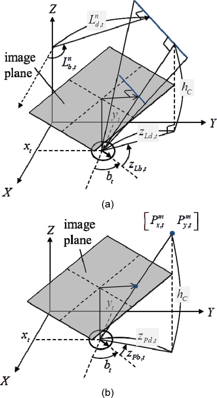
Geometric descriptions of landmark parameters and observation models: (a) line landmark and measurement; (b) point landmark and measurement
For example, line landmarks include the boundaries of the ceiling while point landmarks include the lights and fire sensors. In this paper, both the line landmarks

where the sub-index t refers to the time index;
2.1 System Models
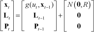
To estimate the metric state vector, we must define the system models. A two-wheeled robot's motion always follows a straight or circular trajectory, which is modelled by a linear and an angular velocity. The motion model is defined as follows:

where ut =[vt wt]
T
represents the linear and angular velocity of a robot, and R is the noise covariance of the motion model. Thus, for the augmented SLAM state
Now, let us think about the observation model. First, we will consider the line landmarks, which are detected on the ceiling boundaries between the ceiling and the wall. Figure 2 gives an example of the line-feature extraction process. A ceiling image is binarized into the ceiling region and the rest by expanding the ceiling region from the image centre, based on the fact that the centre of a ceiling image always belongs to the ceiling region. The ceiling boundary is divided into line segments and the segments are parameterized to obtain line measurements. The detailed extraction process is described in our previous work [17]. The line observation model transforms the distance and angle of a line landmark in the global frame into the robot's frame, as follows:
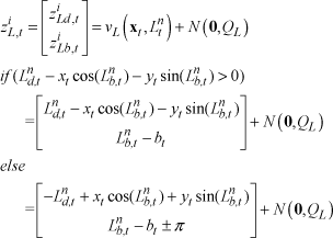
where

Feature extraction process: original image (left), binarized image (centre), refined image, and ceiling boundary (right) [16]
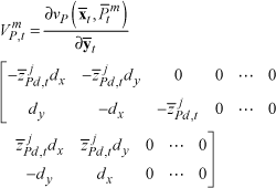
Next, let us think about a point landmark and its observation model. The point observation model transforms the coordinates of point landmarks in the global frame into the robot's frame, as follows:

where
The point landmarks consist of the centre points of electric lamps and circles on the ceiling. Electric lamps are detected by thresholding a ceiling image to extract bright blobs, and circles are detected by a combination of the Canny edge and Hough circle transforms. The point landmark detection methods are detailed in [18]. The feature extraction samples are presented in Figure 3. The three rows show how circular lights, light tubes and circles are detected, respectively, from top to bottom. The left column represents the original images and the right represents the detection results. The two top binary images show bright regions in which to find electric lamps and the bottom is the Canny edge image for circle detection. In the mid-central image, the right blob is detected from reflected light. This blob is falsified by checking whether the blob is inside the ceiling region. The bottom-central image shows four circular edges, but those circles that have a radius less than the threshold are abandoned, as shown in the bottom-left image.

Detection process of the tree different types of point landmarks: a circular electric lamp (top), a fluorescent light tube (middle), and circles (bottom)
2.2 EKF SLAM
In this subsection, the state defined in Eq. (1) is estimated by the EKF. In the EKF, all the states


where C


where Gt is the Jacobian of the motion model with respect to the predicted state
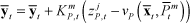
Next, let us explain the correction step. The uncertainty of the state enlarged in the prediction stage is reduced in the following correction stages. When the line measurement


where
where


The formulations introduced so far are the traditional EFK-based SLAM framework, but the traditional method sometimes loses track of the robot's true pose, especially when only a few landmarks are within the FoV. Our main contribution is proposed so as to improve the accuracy of SLAM in such situations. It is described in the next section.
3. Relational Constraints
When a pair of point and line landmarks are simultaneously observed, we can see a geometric relationship between them. This paper proposes to exploit this relationship in order to improve the accuracy of the mapping and localization. More specifically, the relationship is applied as a relational constraint between a pair of landmarks in the constrained-EKF [19] framework. Since the constraint is not obtained from a priori knowledge but rather from an observed geometric relationship, it is considered as a soft constraint with uncertainty
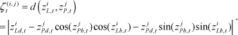
Eq. (19) can be derived from Eq. (4) by substituting

where

Geometric description of a relational constraint. The distance between a pair of line and point measurements is applied as a relational constraint on the corresponding line and point landmarks.
The derivation of Eq. (20) is similar to the derivation of Eq. (19), substituting

The relational constraint with the uncertainty calculated in Eq. (21) is applied in the EKF-SLAM through the following equations:


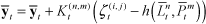
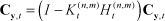
The Jacobian equation of Eq. (22) is divided into the two cases shown here because we take the absolute value in Eq. (20). With equations (22) through to (25), the relational constraint corrects all the related landmarks and the robot's pose - as well as the paired landmarks - in the EKF frame.
At this point, let us discuss the computational issue. When there are multiple line and point measurements, the possible number of pairs of line and point measurements is nL × nP, where nL is the number of line measurements and nP is the number of point measurements. If nL and nP are less than two, as usual, the possible pairs are not overly large for real-time performance. However, when there are several more line and point measurements, namely in the worst cases where nL, nP > 2, applying all the relational constraints of all the possible pairs is computationally heavy and can lead to overconfidence in the state estimation. The overconfidence means that the estimated uncertainty of the state decreases below the actual uncertainty, or even that the covariance matrix can lose its positive definiteness. Therefore, we selectively apply the relational constraints by forming a single pair for each line measurement: a line measurement is paired only with the closest point measurement to the line, whereas a point measurement can be assigned to multiple line measurements. This limitation reduces the computational load for applying constraints when there are more than a couple of measurements, and the performance of SLAM is improved when there are only a few measurements in a sparse map.
4. Experiments
The proposed SLAM was tested in both simulations and a real-world experiment, and we compare its performance here with that of a traditional SLAM. By ‘traditional’ SLAM, we mean the SLAM described up until Section 2. The traditional and proposed SLAMs are the same except that the proposed SLAM utilizes the relational constraints given in Section 3. Four measures are used to evaluate the SLAM performance: trajectory error, line mapping error, number of outlying line landmarks and point mapping error. Because the same map might look different if it uses different origins and orientations, translations and rotations are applied to the coordinates of the trajectory and map prior to assessing the performance of the SLAM. The translations and rotations are represented by a vector:

The transformation

where TrjErr, LineErr and PointErr denote the trajectory error, line mapping error and point mapping error, respectively, such that they all depend on
where L is a true line landmark and L̄ is a SLAM line landmark. A SLAM line landmark is associated with the closest true line landmark if two landmarks overlap. The following subsections describe the experimental environments and conditions and provide the results of the performance evaluation.
4.1 Simulation Results
First, we conducted simulations to test the performance of the proposed SLAM in a synthetic environment. A number of line and point features were installed in the synthetic environment, and the environment was more complex than our real-world experimental conditions, as described in the next subsection. Two different environments were used that differed in size, trajectory lengths and the number of landmarks, as shown in Figure 5. The first map -called M1 - consists of four rooms with hallways around them. It has 84 line landmarks and 34 point landmarks. The robot travelled along 20 different trajectories for 500 time-steps. The second map - M2 - includes 76 line landmarks and 51 point landmarks and has a relatively large and complex structure. Again, the robot travelled along 20 different trajectories for 1,000 time steps in M2.

Simulation environments and the true trajectories of M1 (a) and M2 (b)
Since the inputs suffer from Gaussian random noise, the simulation results are not deterministic (even through the same trajectory in the same environment). In the simulations, the noise conditions are set as R = diag (0.01, 0.01, 0.001) and QL = QP = diag (0.01, 0.001). To examine the statistical reliability of the performance evaluation, 20 runs were made with different trajectories. The trajectory errors are evaluated for each trial and the mean and standard deviation are abstracted from the results. The mean value measures the accuracy of the state estimation and the standard deviation evaluates the precision. The trajectory depicted by the dotted line in Figure 5 is an example of the trajectories used in the simulation. The square mark represents the robot's starting point.
The simulation results for M1 are provided in Figure 6 and Table 1. Figure 6 shows the results for one of the 20 simulation runs. In the figure, the dotted and solid trajectories depict the true and estimated trajectories, respectively. Equally, the dotted and solid lines represent the true and estimated line landmarks, respectively. Finally, the triangular and circular marks represent the true and estimated point landmarks, respectively. As the figure shows, the results of using the proposed SLAM are closer to the ground truth than those using the traditional SLAM.
Comparison of SLAM errors in M1

Simulation results of traditional SLAM (a) and the proposed SLAM (b) in M1
The numerical results of all 20 simulations are summarized in Table 1. The table shows the means and standard deviations of the four error measures for each method and their reduction using the proposed SLAM as compared to the traditional SLAM. The trajectory error is reduced by 17.6%, and the line and point mapping errors are reduced by 18.0% and 26.4%, respectively, using the proposed method. The standard deviations of the errors are also substantially reduced. The number of outlying line landmarks is reduced to 0.85, which means that almost every line landmark estimated by the proposed SLAM is associated with the corresponding true line landmark.
Figure 7 and Table 2 provide the simulation results for the environment M2. The figure displays the results for one of the 20 simulation runs. The dotted and solid trajectories, the dotted and solid lines, and the triangular and circular marks, all have the same meanings as in Figure 6. As in the simulation for M1, the proposed SLAM estimates the trajectory and the map much more accurately (i.e., closer to the ground truth) than the traditional SLAM. In Table 2, the simulation results of the two methods are summarized. The trajectory error of the proposed method is much smaller than that of the traditional method, while the mapping errors remain almost the same. The line mapping error may appear degraded in our method, but in fact the traditional method has a larger line mapping error dispersed in the many outlying landmarks. A large error for a line landmark makes it appear unrelated to the corresponding true landmark and thus to appear to be an outlying landmark. With the proposed method, the number of outlying line landmarks is reduced by 33.9% and the standard deviations of all four errors are decreased. The decrease in standard deviations indicates that the relational constraint used in the proposed SLAM stabilizes the performance. From the simulation results of M1 and M2, it can be concluded that the use of relational constraints between features improves the accuracy and the reliability of the SLAM.

Simulation results of the traditional SLAM (a) and the proposed SLAM (b) in M2
Comparison of the SLAM errors in M2
4.2 Experimental Results
In this subsection, we describe the experiment conducted to demonstrate the performance of the proposed method for real-world applications. In this experiment, the robot is set up as shown in Figure 8. It is equipped with an embedded camera on top, and the camera provides grey images with a 320-by-240 pixel resolution. We suggest that the camera should have at least 3 m of ceiling within the field of view for consistent landmark detection. The robot reads a velocity and a ceiling image at each step, and line and point features are extracted from the ceiling images, as described in Section 2.
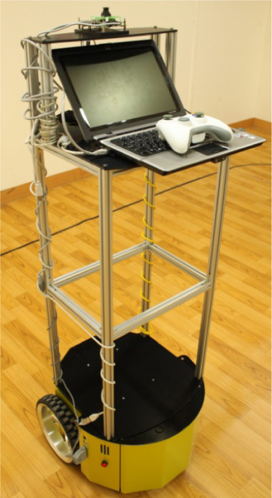
A mobile platform equipped with a ceiling camera
Figure 9 shows the floor plan of the experimental site and the true map of line and point landmarks. The site is on the fourth floor of the Technopark in the city of Bucheon. The true map (the ground truth of the map) was reconstructed from the floor plan of the building and then manually corrected. The robot moved around the U-shaped hallway in the building for 5,232 sampling times, and the map was about 17 m × 18 m. The true trajectory, shown in Figure 9(b), was obtained from the indoor localization system, named Stargazer [20].

Floor plan of the experimental site (a) and the ground truth trajectory and map (b)
The results of both SLAM methods are shown in Figure 10. The dotted and solid trajectories, the dotted and solid lines, and the triangular and circular marks, all have the same meaning as in the figures for the simulations. The traditional SLAM updates line and point landmarks independently (i.e., without regard for their relationships), and the resulting estimations of the map and the trajectory are quite different from the ground truth, as shown in Figure 10 (a). In particular, when the robot is far away from the starting location (in the right-hand part of the map), the estimation performance is seriously degraded. In contrast, the proposed SLAM exploits the relational constraints between the line and point landmarks and estimates the map and trajectory extremely closely to the ground truth over the whole environment. The numerical results are summarized in Table 3. The trajectory error of the proposed SLAM is reduced almost by half compared to the traditional method. In addition, the line and point mapping errors are significantly decreased, by 23.6% and 36.3%, respectively. However, the number of outlying lines remains the same because the environment is not as complex in the experiment as it is in the simulations, and association failures rarely occur in the simpler environment. The three outlying line landmarks arise from line landmarks that do not belong to the ground truth map.

Experimental results of the traditional SLAM (a) and the proposed SLAM (b)
Comparison of the SLAM errors in the experiment

To evaluate the capability of its real-time operation, the processing times for feature extraction and state estimation were measured. The feature extraction process takes 38.4 ms and the state estimator takes 0.3 ms on average over sampling times on a computer with an i5-2500 CPU and 4GB RAM. Therefore, the total mean processing time is 38.7ms, which is fast enough to operate in real-time.
5. Conclusions
This paper proposes a method that utilizes observed relational constraints between different types of features to improve accuracy of SLAM estimation in environments with sparsely distributed landmarks. CV in an indoor environment provides static and robust features, but those features are not plentiful. Therefore, additional information is needed for good performance. We employ the distance between line and point landmarks as relational constraints, which prevents the line and point maps from becoming misaligned, thereby increasing localization accuracy. We implement this idea using line and point features in the EKF SLAM framework. Simulation and experimental tests of the proposed method showed improved results compared with the traditional method that updates the state vector without using relational constraints. The experimental results provide a real-world demonstration of our method, showing that the trajectory and maps estimated using relational constraints are closely fitted to the ground truth. Our algorithm was also tested through simulations so as to verify the performance of the proposed SLAM in more complex, larger environments, through various trajectories. The simulation results show that our method successfully improves the general performance of SLAM. Furthermore, our approach's utilization of relational constraints also improves the stability of the estimation filter.
In future work, we plan to apply relational constraints between various kinds of features or between features of the same type for conditions in which SLAM suffers from sparse landmarks. Furthermore, we may need to develop new relational constraints in addition to the distance measure used in this paper, in order to constrain the landmarks' locations more tightly in multiple dimensions.
Footnotes
6. Acknowledgments
This research was supported by the Basic Science Research Programme through the National Research Foundation of Korea (NRF), funded by the Ministry of Education, Science and Technology (NRF-2013R1A2A2A01015624).