
Abstract
In this paper, an online self-tuning precompensation for a Proportional-Integral-Derivative (PID) controller is proposed to control heading direction of a flying robot. The flying robot is a highly nonlinear plant, it is a modified X-Cell 60 radio-controlled helicopter. Heading direction is controlled to evaluate efficiency of the proposed precompensation algorithm. The heading control is based on the conventional PID control combined with an online self-tuning precompensation so that both the desired transient and steady state responses can be achieved. The precompensation is applied to compensate unsatisfied performances of the conventional PID controller by adjusting reference command. The precompensator is based on Takagi-Sugeno's type fuzzy model, which learns to tune itself online. The main contribution of the proposed controller is to enhance the controlled performance of the conventional PID controller by adding a self-tuning precompensator on the existing conventional PID controller. The results show that the conventional PID controller with an online self-tuning precompensation has a superior performance than the conventional PID controller. In addition, the online self-tuning precompensation algorithm is implemented simply by adding the precompensator to the existing conventional PID controller and letting the self-tuning mechanism tune itself online.
Introduction
A flying robot developed at AIT is modified from X-Cell 60 radio-controlled helicopter. It is developed to support autonomous flight control covering wide-mode missions of operation from hovering to other maneuvers. Currently, there are many researches on development of autonomous flying robots with different control techniques (Srikanth et al, 2003). The conventional PID controller is still widely used due to its simple implementation and tuning (Gregg et al, 2003). The weakness of the conventional PID controller is that it exhibits poor performance when applied to control the system that contains nonlinear and cross coupling effects. Various techniques are applied to accomplish this purpose, ranging from adjusting the controller gains to using the precompensation technique. The latter has many advantages since it is simple to implement and safe. In the precompensation technique, the controller gains are the same as the ones obtained in stable response and the precompensated amounts can be bounded within reasonable ranges of safety.
Since the introduction of fuzzy set by Zadeh (Zadeh, 1965), fuzzy logic-based controllers have received considerable interest from many researchers. Jong et al. (Jong et al., 1993) applied a fuzzy precompensated PID controller to control position of a DC servomotor by compensation of overshoots and undershoots of transient response under load variation. In our work, the conventional PID controller with an online self-tuning precompensation is used to control heading direction of our flying robot. The precompensator is based on the Takagi-Sugino's type fuzzy model. There are three main reasons to apply the precompensator to overcome the unsatisfied controlled performance. Firstly, to eliminate steady state error. Even when the integral term is included in the controller, steady state error still occurs in the results, due to many factors such as, deadzones in the linkage mechanism, slow speed and delay of the actuator, varying of rotation speed of the tail rotor and unsymmetrical yaw dynamics in clockwise and counter clockwise rotations (Raymond, 1995). Secondly, to reduce cross coupling effected from the Z-axis. Lastly, to decrease settling time in the yaw dynamics response. By using online self-tuning precompensation with the conventional PID controller, the system exhibits superior transient as well as steady state performances.
The precompensation technique described in this paper is different from the precompensation addressed by Jong et al (Jong et al., 1993). Firstly, the system and fuzzy model are totally different. In Jong's work, the fuzzy model is based on Mamdani's model. In this work, the fuzzy model is based on Takagi-Sugeno's model. Secondly, technique of tuning of the fuzzy logic is different. The technique used by Jong is based on manual tuning. In this work, it is based on online self-tuning by gradient descent method. Thirdly, compensation design by Jong is based on an attempt to compensate overshoots and undershoots in the transient response when the conventional PID controller is applied to a DC servo position controlled testbed with load varying. In this work, the design is based on compensation of steady state error and reduction of cross coupling effects as well as improvement of settling time when the conventional PID controller is applied to control heading direction of the flying robot.
This paper is organized as follows. In section 2, we describe architecture of our flying robot. Section 3 describes control structure of the precompensation. Section 4 describes experimental results, which demonstrate performances of the algorithm. Section 5 shows the fully autonomous flight experiment. Finally, the conclusion is made in section 6.
Flying Robot and Flight Control System
Our flying robot is a modified X-Cell 60 radio-controlled helicopter with a main rotor diameter of 1.80 meters. The robot's OS91 glow plug engine has power rating of 3.0 HP, resulting in the maximum payload of 5.0 kg and flight duration of approximately 15 minutes. Fig. 1 shows the flying robot and its avionics box of the robot. The avionics box, which is installed underneath the robot, contains the following processors and sensors.
An onboard PCM3350 PC-104 flight control computer running at 300 MHz. Two 68HC11 microprocessors. The first microprocessor generates pulse width modulation (PWM) signals to drive 4 actuators. The second microprocessor is used to drive and read an ultrasonic altimeter. A 3DM-GX1 attitude and heading reference sensor containing three angular rate gyros, three orthogonal linear accelerometers, and three orthogonal magnetometers to provide three orientation angles (roll, pitch, yaw). An OEM4 RT-20 GPS card. The GPS provides latitudes and longitudes information within 20 cm CEP (circular error probable) when operated in a real time kinematics mode. An SRF-04 ultrasonic altimeter to provide ground-to-robot distance at the update rate of 25 Hz. A circuit board containing actuator-interfacing circuit and control signal multiplexing circuit.

Flying robot testbed
In the control inner loop, the PC-104 computer receives attitude information (roll, pitch, and yaw) from the attitude and heading reference sensor and runs the core PID attitude control at the rate of 50 Hz, effecting the aileron, elevator and rudder actuators. The control outer loop, the position control, is run at 5 Hz to generate the roll, pitch and yaw (heading) attitude commands for the inner loop while the height control is run at 25 Hz to control the position in Z-axis. The flying robot continuously communicates with ground station via an 802.11b wireless network using TCP/IP protocol. The communication occurs every 2 seconds and the range of communication covers up to 0.5 km. The ground station sends DGPS correction signal and updates user commands to the flying robot. Fig. 2 shows the flight control system of our flying robot.

Flight control system
Tail rotor on the flying robot is used to control the robot heading direction by altering pitch angle on the tail rotor blades. By doing so, it can increase or decrease the yaw angular moment of the robot. The robot actuators are the S9206 dc servomotor, accompanied with GY401 rate gyros.
To evaluate control performance of online self-tuning precompensation on the conventional PID controller. The engine governor is always turned off during the experiments.
Normally, control performance of a system can be improved by tuning of the controller gains. This method can harm the flying robot, since the robot fly in the turbulent air where the system parameters change all the time. The proposed algorithm in this paper applies the method that adjusts the heading reference command of the controller instead of directly adjusts the controller gains. The precompensator uses the gradient descent method to tune the fuzzy parameters. The originality on this proposed method is the use of the conventional PID controller together with the online self-tuning precompensator to control heading direction of the flying robot. The steady state error is eliminated online during the flight. The cross coupling effect to the control axis is also reduced. It is a kind of an adaptive control, since when the robot dynamics changes, the control system will tune itself and adapt to the new flight condition. The main advantage of online tuning is that it makes the development simpler in practical. Unlike in the work of Jong et al (Jong et al., 1993), where the fuzzy parameters are tuned by the operator experience to obtain the best result. In this proposed method, the fuzzy parameters are adapted based on the control performance. The process is done online automatically.
An online self-tuning precompensation for the conventional PID controller is proposed and applied to control heading direction of the flying robot. Fig. 3 illustrates block diagram of the controller. The diagram consists of the conventional PID controller and the online self-tuning precompensator.

Online self-tuning precompensation of PID controller
Purpose of the precompensation is to modify reference command to compensate steady state error, overshoots, and cross-coupling effects. The precompensator consists of two parts; fuzzy logic and online self-tuning mechanism. Heading error, e(k), and change of heading error, Δe(k), are determined as followings.


Two input variables of the fuzzy logic are the normalized heading error, e
n
(k), and the normalized change of heading error, Δe
n
(k). They are obtained by multiplying the heading error, and the change of heading error, with their corresponding scaling factors G1 and G2, as followings.


The normalized correction value, γ
n
(k), is the result of mapping from e
n
(k) and Δe
n
(k) to γ
n
(k) based on Takagi-Sugeno's fuzzy model as shown in equation (5).

To obtain the actual correction value, γ(k), the normalized correction value must be multiplied with a coefficient G3 as shown in equation (6).

The precompensated reference command, y'
r
(k), is the sum of the reference, y
r
(k), and the correction term, γ(k), as shown in equation (7).

The precompensated reference command is, finally, used as the input to the conventional PID controller as followings.

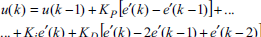
In equation (8), the error e'(k) is the tracking error between the precompensated heading reference, y' r (k), and the actual heading, y(k). Equation (9) represents velocity version of PID controller. The controller output, u(k), is then converted to PWM signal to drive rudder actuator of the flying robot.
The precompensation applies Takagi-Sugino's fuzzy model. The model is formulated following the form (John, Y. & Reza, L., 1998).


Membership functions of the normalized heading error (a) and the normalized change of heading error (b)
The output of fuzzy logic is calculated by the weight average method (Kevin, M. P. & Stephen, Y., 1997), given inputs (e
n
(k), Δe
n
(k)), the final output is the weight average of


Triangle membership function
The second part of the precompensator is the online self-tuning mechanism. The self-tuning method of the precompensator applies gradient descent technique. The precompensator is tuned by minimizing a cost function. The cost function is defined as the square of the difference between the actual heading and the reference command as expressed in equation (14).

In the self-tuning, only the parameters in the consequent part of the rules are updated. Self-tuning of the precompensator parameters,


In the experiments, performances of the conventional PID controller and the PID controller with online self-tuning precompensation are compared. The PID gains, which result in a satisfactory system performance, are the result of trial and error of many experiments. Finally, the PID gains used in the experiments are K
P
= 10, K
I
= 0.0125 and K
D
= 6.4. The fuzzy logic consists of 49 rules. The heading reference is compensated when the heading error is in the range of ±80 degrees. So, scaling factor for the heading error is selected at
The heading control loop and the precompensation loop in the experiment are run at 50 Hz. Fig. 6 shows results of the flight experiments (PID with and without the online self-tuning precompensation). Fig. 7 shows the fuzzy output of the precompensator. In Fig. 7(a), the correction value is zero because all of the consequent parts of the fuzzy logic are initialized at zero. Fig. 7(b) shows the outputs of the precompensator after the tuning process is done.

(a) Heading control experiment and (b) zoom-in figure of (a)

Compensation output (a) before tuning and (b) after tuning
Fig. 6 illustrates significantly improvement when the online self-tuning precompensation is turned on at time t = 90 seconds. At the beginning, only the conventional PID controller is applied, it results in a steady state error in the output response. By the precompensation, the steady state error is eliminated.
Fig. 8(a) shows the effects of cross coupling from Z-axis of flying robot to the heading control performance. Firstly, the precompensation algorithm is turned off. The flying robot takes off and head to 120 degree by the conventional PID control. The flying robot then rapidly changes its altitude from 1 meter to 3 meters and changes back to 1 meter again. By the conventional PID controller, the heading moves away from the setpoint to 50 degree in the counter clockwise direction, which is 70 degrees away from the setpoint. The similar experiment is conducted on the flying robot again by using the online self-tuning precompensation. The result is shown in Fig. 8 (b). The precompensation significantly reduces the effect of cross coupling.

Effects of cross coupling by (a) PID alone and (b) PID with online self-tuning precompensation
The other experiment tests the effect of self-tuning as shown in Fig. 9. The flying robot lands at time t = 5 seconds. During landing, self-tuning is saturated. Then the flying robot takes off again at time t = 32 seconds. The result shows the efficiency of the online self-tuning mechanism of the precompensation.
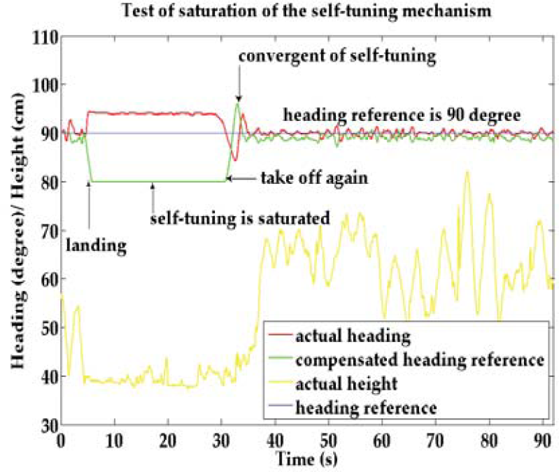
Saturation of an online self-tuning precompensation
In order to test the control performance of the proposed algorithm, the flying robot is commanded to fly in a 3 meters by 3 meters square area. The flight experiment is shown in Fig. 10 and Fig. 11.

Autonomous flight test with heading point to 0 degree
There are 4 points marked with the white spot on the ground. The flying robot is automatically controlled in 6 DOF, including roll, pitch, yaw, X-axis position, Y-axis position and Z-axis position. The altitude command is 1.5 meters above the ground.
The X-Y position commands are changed sequentially among the 4 marked points. The X-Y position commands are changed every 30 seconds. The heading command is maintained at 0 degree (pointing to the North). Fig. 10 shows the flying robot tracking to the marked points.
In Fig. 11, the online self-tuning precompensation is turned on at time t = 58 seconds. In the fully autonomous flight, the heading control was disturbed by air turbulent and ground effect. From the results, the zero degree heading command can be maintained with good performance.

Recorded heading data during autonomous flight
The proposed control algorithm is also compared with Jong's method (Jong et al., 1993). Even though the experiment results shown similar good control performance in the elimination of the steady state error and the compensation of unsatisfied performances similar to Jong's method, the merit of our algorithm is the online self-tuning. Manual tuning is unnecessary. The transient response from our algorithm has the overshoots only when the heading reference is changed rapidly as a step command. However, in the real application, the heading reference is mostly not changed rapidly; since the flying robot is commanded to fly following a smooth planned trajectory.
In the experiments, the learning rate is fixed. By the gradient descent method, too low learning rate makes the tuning mechanism learn very slowly. In contrary, too high learning rate makes the parameters in the consequent part and cost function diverge. The learning rate effects directly to the performance of the self-tuning mechanism. The overshoots in the output response can be eliminated by varying learning rate. Adaptive schedule of the learning rate is a topic in the further research.
In this paper, the conventional PID controller with and without online self-tuning precompensation were applied to control heading direction of a flying robot. The conventional PID controller was used as the basis control method. The adaptable component that used as the command precompensator was successfully applied. There are two advantages of the proposed method in improving the control performance of the conventional PID controller. Firstly, the existing PID controller is still used. Secondly, the precompensator parameters are tuned automatically online. The precompensation is very simple to be integrated into the existing conventional PID controller. This is simply done by adding the precompensation in front of the existing PID controller. The performance was evaluated by many flight experiments. The results demonstrated good performance of online self-tuning precompensation. The conventional PID controller with online self-tuning precompensation provided much better responses compared to the conventional PID controller alone. The steady state error was eliminated. The effect of cross coupling was reduced. The settling time was decreased. However, as shown in the results, there existed overshoots in the output responses. This was because of the fixed learning rate. In order to achieve a better result, variation of the learning rate is required.
Footnotes
7. Acknowledgement
This research project is financially supported by Thailand Research Fund.