
Abstract
In this paper a gain scheduling approach is proposed for the hybrid force/velocity control of an industrial manipulator employed for the contour tracking of objects of unknown shape. The methodology allows to cope with the configuration dependent dynamics of the manipulator during a constrained motion and therefore a significant improvement of the performance results. Experimental results obtained with an industrial SCARA manipulator demonstrate the effectiveness of the technique.
Introduction
The capability of performing autonomously a contourtracking task of an object of unknown shape is required for an industrial robot manipulator in order to be successfully adopted, without the operator intervention, in many applications such as grinding (Thomessen, T. & Lien, T. K. 2000), deburring (Ferretti, G.; Magnani, G.; Rocco, P. 2000), shape recovery (Ahmad, S. & Lee, C. N. 1990), polishing and kinematic calibration (Legnani, G.; Adamini, R.; Jatta, F. 2001). Methodologies for this purpose have been investigated for many years and many solutions have been proposed. In particular, many schemes based on hybrid force/position (velocity) control (Raibert, M. H. & Craig, J. J. 1981, Craig, J. J. 1989), either with or without an internal position/velocity loop, have been devised (see, for example, Starr, P. 1986, Yu, K. & Kieffer, J. 1999). However, they are still very rarely employed in industrial settings, where the availability of these functionalities would be very appreciated in order to cut the production costs and to improve the quality of the products.
This might be due to the fact that many times new methods are diffcult to implement for the industrial context, where the cost/benefit ratio has to be always taken into account (for example they often involve an accurate estimation of the robot model), and their effectiveness is rarely discussed from an industrial point of view (for example there is a lack of experimental results that really show the cases where a given technique can be successfully adopted and where it may fail).
In order to make a step in the direction of solving those practical problems that often arise in industrial settings, a method to compensate for joint friction have been proposed in Jatta, F.; Legnani, G.; Visioli, A. 2006, Moreover, the use of a velocity feedback in order to dampen oscillations that occur in a significant portion of the workspace due to the configuration dependent dynamics of the manipulator in a constrained motion has been discussed in Jatta, F.; Legnani, G.; Visioli, A.; Ziliani, G. 2006.
In this paper, the use of a gain scheduling approach in order to further enhance tracking performances over wider portions of the workspace and to allow reliable and effective operations in very different working conditions is proposed.
Experimental setup
The experimental set-up available in the Applied mechanics Laboratory of the University of Brescia consists of an industrial robot manipulator manufactured by ICOMATIC (Gussago, Italy) with a standard SCARA architecture where the vertical z axis has been blocked since a planar task is addressed. A detailed dynamic model is described in Visioli, A. & Legnani, G. (2002). Both links have the same length of 0.33 m. The two joints are actuated by means of two DC motors that are driven by conventional PWM amplifiers and position measurements are available by means of two incremental encoders with 2000 pulses/rev. resolution. Harmonic Drive speed reducers are present and the reduction rate is 1/100 for both joints. Velocity is estimated through numerical differentiation whose output is then processed by a low-pass 2-order Butterworth filter with a 100 Hz cut-off frequency and a 1.0 damping ratio. An ATI 65/5 force/torque sensor capable of measuring forces in a range of ±65 N and with a resolution of 0.05N is mounted at the manipulator's wrist. The corresponding signals are processed at 7.8 kHz frequency by an ISA DSP based board.
The contact is achieved by means of a proper plastic probe. An 8 mm diameter ball bearing is fitted at its end with the aim of reducing tangential friction forces that may arise from the contact with the piece, symplifing the contact force direction estimation. The PC-based controller is based on a QNX4 real time operating system and the control algorithms are written in C/C++ language. Acquisition and control are performed at a 1 kHz frequency.
Contour tracking
Problem formulation
A sketch of the SC ARA robot is shown in Fig 1. Frame (0) refers to the robot base, while task frame (T) has its origin on the robot end-effector with its n and t axes that are directed respectively along the normal and tangential direction of the contour of the piece, whose geometry is assumed to be unknown; 9 is the angle between n axis and × axis of frame (0). Let


Sketch of a SCARA robot following a contour
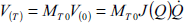
Aim of the contour tracking task is to control the normal force and the tangential velocity of the robot end-effector along the n and t directions of the task frame (T). These directions can be easily detected assuming negligible the friction force in the tangential direction (this is achieved by providing a ball bearing at the probe) by on-line estimating the angle ϑ as:

In industrial applications like deburring or grinding the tangential friction force cannot be negletted; in these cases the contact direction estimation (eq. 1) can be suitable compensated using cutting force models (Duelen, G.; Munch, H.; Surdilovic, D.; Timm, J. 1992) or measuring the torque of the milling spindle (Ziliani, G.; Legnani, G.; Visioli, A. 2005).
The following hybrid force/velocity control law has been initially considered (see the control scheme in Fig 2)

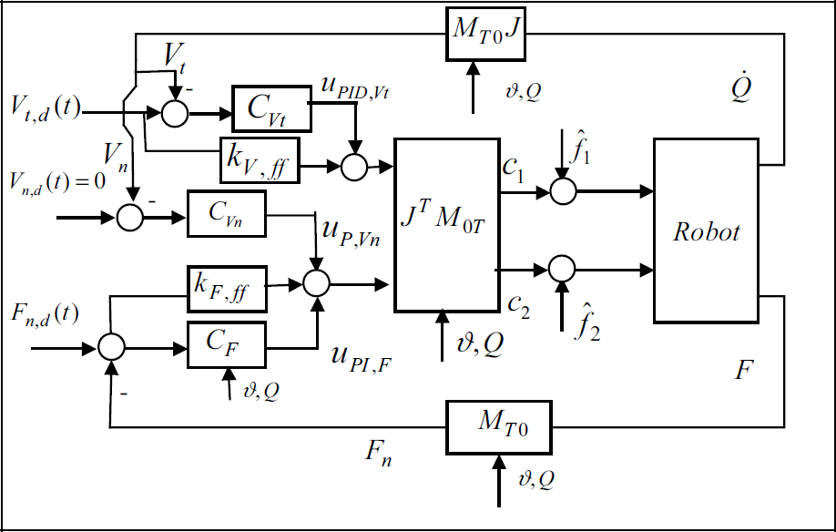
Basic hybrid force/velocity control scheme.
Conversely, the adoption of a normal force velocity feedback loop has been proven to be effective to compensate for the large force oscillations due to the effects of link masses (and joint elasticities) in a large portion of the workspace (Jatta, F.; Legnani, G., Visioli, A.; Ziliani, G. 2006).
It is worth stressing that a model of the robot is not required for the implementation of the control law (2).
Despite the use of the velocity feedback allows to significantly reduce the manipulator configuration dependent force oscillations in a large portion of the workspace, this solution is not suffcient in general when the two links tends to be aligned, i.e. toward the external limit of the workspace where the manipulator is in a singular configuration.
This fact can be explained by analysing the inertial ellipsoids that describe, for a given manipulator configuration, the force required to generate a unitary end-effector acceleration in all the possible directions (Jatta, F.; Legani, G., Visioli, A.; Ziliani, G. 2006, Tsai L. W. 1999). It can be determined that the diameters of the inertial ellipsoids are of very different length and vary significantly in the working area. This implies that satisfactory performances can not be achieved with a standard (linear) PI(D) based control law. The same reasoning applies if the stiffness ellipsoids, (that describe the force required to generate a unitary end-effector displacement) are considered. A solution to this problem can be qualitatively deduced by analysing a 1 d.o.f. simplified model of a constrained manipulator. Fig 3 shows the arm represented as a mass m
eq
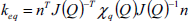
whose position is X1 and where f is the force exerted by the actuator. A damping term may be present due to friction but the joint friction compensation should keep its influence low and therefore this term can be neglected. The value of the equivalent mass for a given configuration of arm and direction of contact can be calculated as:

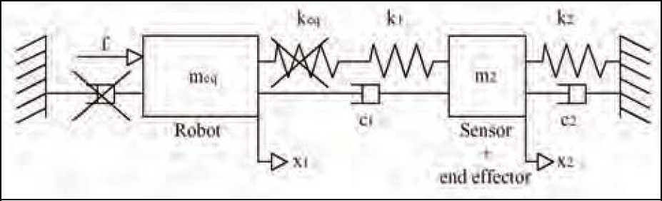
Model of the manipulator in contact with the environment.
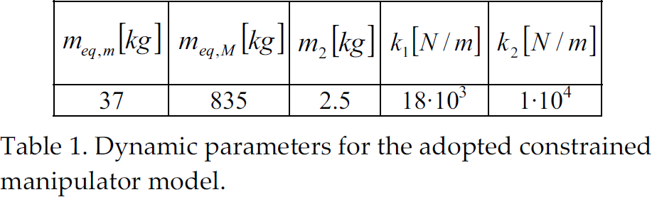
In order to determine the values of the dynamic parameter for the adopted model, the values of the stiffness of the joints have been first determined by means of suitable ad-hoc experiments (Volpe, R. 1990). It results X1 = 35.1 · 103 Nm/Rad and X2 = 12.6 · 103 Nm/rad. Similarly, the value of the stiffness k1 has been determined as k1 = 18 · 103 Nm/rad. It can be deduced that the equivalent stiffness k eq of the arm in any given contact direction (see eq. 4) is much higher than the stiffness k1 of the vertical holder of the end-effector and therefore the term k eq can be neglected in the series of the two terms. Then, the values of the inertial parameters have been determined by means of a least squares parameter estimation procedure (Indri, M.; Calafiore, G.; Legnani, G.; Jatta, F.; Visioli, A. 2002). Some of the resulting model parameters are shown in Table 1 where m eq,m and m eq,M are respectively the minimum and maximum values of m eq that result by considering a large part of the workspace (the area that is very close to the workspace limit has been excluded as these values tends to infinite). Regarding the values of the damping terms c1 and c2, they are very difficult to estimate and the sensible values of c1 = 50 and c2 = 20 have been selected (Volpe, R. 1990). In any case, changing these values does not affect significantly the results.
Dynamic parameters for the adopted constrained manipulator model.
Assume that a proportional force control is applied to this model, i.e.:

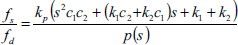
Then, the closed-loop transfer function results to be:

It is worth underlying at this point that just a qualitative analysis has been performed using the simplified model of Fig 3, since the actual system is obviously time-variant and nonlinear. However, this suggests the use of a gain scheduling approach to cope with the configuration dependent dynamics of the manipulator during a contour tracking task, namely, the adoption of a time varying proportional gain (the integral time constant is maintained constant) in the PI force controller. The value of the proportional gain k
p
is therefore allowed to vary in a given interval whose endpoint values k
p
, min = 0.005 and k
p
, max = 0.13 have been chosen with a simple trial-and-error procedure in such a way that they are appropriate (constant) values for low and high equivalent mass respectively. A linear function has been then selected to determine the value of k
p
depending on the equivalent mass m
eq
in the contact force direction, i.e. its value is calculated according to the expression:

Fig 4 exemplifies how the position of the poles of the resulting closed-loop transfer function typically changes when a constant value of the proportional gain (k p = 14 in this case) is applied, whilst the value of m eq increases within its range. It turns out that the position of the poles (i.e. their natural frequency and damping factor) significantly changes depending on the manipulator equivalent mass (i.e. on the manipulator configuration and force direction) and therefore it might not be possible to find a tuning for the hybrid force/velocity controller that provides satisfactory performances in a wide range of configurations. Conversely, if k p varies proportionally to m eq (e.g. k q = m eq / 3.5) then the result plotted in Fig 5 is obtained. It is evident that in this case the pole location is practically the same for all the possible situations.

Poles of the system with a constant k p when the value of the equivalent mass m eq increases.
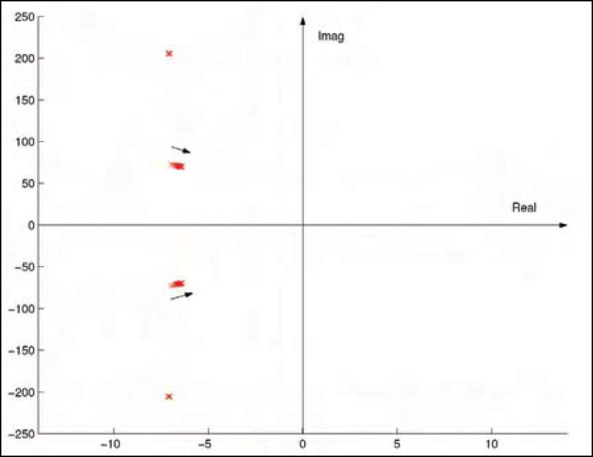
Poles of the system when the value of the equivalent mass m eq increases with k p that varies proportionally to m eq .
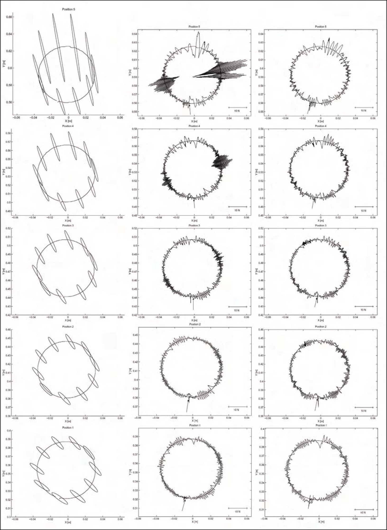
Inertial ellipsoids (left column) and normal force errors obtained with a standard PI controller (central column) and with the gain scheduling approach (right column) for different disk positions.
In order to verify the effectiveness of the gain scheduling approach an experimental campaign has been performed. First, a metallic disk with a diameter of 60 mm, placed in five different positions along the y-axis with increasing distance from the origin, has been tracked by employing the control law (2) with both a standard force PI controller (k p = 0.03) and the gain scheduling method. In all the cases, the normal force set-point was 20 N, while the tangential velocity set-point was 5 mm/s. The relatively small diameter of the piece, compared to the manipulator size, allows the study of the effect of the force direction variation only, because during the path following the manipulator configuration does not change significantly (for a single disk position) while the contact force makes a complete revolution.
The positions of the disk in the robot workspace and the corresponding robot configurations are reported in Fig 6. Fig 7 shows in the left column the inertial ellipsoids calculated (see Section 4) for the disk in the different positions, in the central column the (normalised) normal force error collected during the tracking of the disk (in the clockwise direction, starting from the point indicated by a small arrow) by using the constant proportional gain and in the right column the force error obtained by using the gain scheduling. Note that the normalised force error has been plotted on the path reconstructed using the forward kinematics.

Position of the disks in the manipulator workspace.

Position of the complex shape in the manipulator workspace
Comparing these figures it is possible to recognize that, in general, the zones that present low equivalent mass in the contact force direction match with the zones where large and rapid force error oscillations occur. This can be explained by considering that the (constant) proportional gain has been tuned for a medium value of the equivalent mass and, as the value of m eq decreases, the (corresponding) too high value of k p tends to reduce the damping of the system. Actually, the velocity feedback provides the necessary damping effect in a wide portion of the workspace, but as the robot end-effector get closer to the limit of the workspace, i.e. for positions 4 and 5 of the disk, indeed the force error amplitude in some configurations reaches values that might yield to the loss of the contact. Detuning the (constant) proportional gain would imply a reduction of oscillations for a low equivalent mass but, on the other side, it would cause a loss of contact where the equivalent mass is higher. Conversely, if the gain scheduling approach is employed, a clear improvement in the performance appears. Indeed, comparing the results, it can be seen that high amplitude force oscillations disappear in the zones with low equivalent mass and no significant variations in the performance are noticed in the other zones.
In order to test further the performance of the new controller, a wooden piece of a very complex shape has been tracked. The shape covers a great part of the manipulator workspace (see Fig 8) and presents convex and concave curves.

Force ellipsoids for the piece with a complex shape plotted on the contour.
The stiffness ellipsoids plotted along the path are reported in Fig 9. The tangential velocity set-point is 20 mm/s and the contact force set-point is 20 N. The piece was tracked in the counter clockwise direction. The contact force error plotted on the reconstructed path is plotted in Fig 10.

Normalised force errors during the contour tracking of the piece with a complex shape

Normalised values of the PI force controller (scheduled) proportional gain plotted on reconstructed path.
It has to be stressed that without the use of the gain scheduling it was not possible to accomplish the task due the numerous contact losses.
The normalised value of the force PI controller (scheduled) proportional gain depending of the contact point is plotted in Fig 11, while the value of the proportional gain along the time axis is reported in Fig 12 (the constant proportional gain employed in the experiments of Fig 7 is plotted together for comparison). Finally, the normal force collected during the contour tracking is plotted in Fig 13. It appears again that similar performances are achieved along the whole path, despite the dynamics varies significantly during the task.

Values of PI force controller (scheduled) proportional gain during the task compared to the constant gain used in the experiments of Fig 7.

Contact force during the tracking of the shape.

The SCARA robot during the contour tracking of a complex shape
It is worth noting that the tangential velocity can be increased up to 50 mm/s without a loss of contact (obviously the normal force error increases). A video of this experiment is available at: www.ing.unibs.it/˜visioli/GainScheduling.html.
A picture of the robot during the contourtracking of the complex shape is reported in Fig 14.
Summarizing, it results that, despite high performances are achieved with the original controller when the (unknown) piece to track is situated in a large portion of the workspace, this portion is significantly widen by employing the devised gain scheduling approach (practically the whole workspace can be adopted). Further, the devised method allows in general the tracking of more complex shapes and to increase the tracking velocity.
In this paper it has been shown that the performances of a force/velocity controller in the contour tracking task of unknown objects are strictly depending on the robot configuration and on the contact force direction. A gain scheduling approach has been proposed to cope with these problems considering a simple two-mass time-varying model of the manipulator in contact with the environment.
It has been shown that this technique allows to obtain small normal force errors in the whole workspace of the robot and for all the robot configurations and force directions.
Experimental results obtained with a SCARA manipulator in the contour tracking of a 60 mm disk placed in different positions in the work space demonstrate the feasibility of its implementation and show the improvements due to this approach. A complex shape that covers a great part of the manipulator workspace has been tracked reaching 50 mm/s tangential velocity.