
Abstract
In this paper, we develop a robot with the ability to secure human safety in human-robot collisions arising in our living and working environments. The human-symbiotic service robot using compliant hybrid joints realizes human safety, absorbs impact force, and fulfills task. In unexpected or expected collisions with human, the arising impulse force is attenuated effectively by the proposed physical model. Owing to the displacement of the links, several recovery controls have been developed for the end-effector to maintain its desired task position after the collision. The force attenuation property has been verified through collision simulations and experiments in that the capability of the proposed passive arm in overcoming the limitations of active compliance control has been demonstrated.
Introduction
Today, robots are expected to provide various services directly to humans in environments, this situation has led to the idea of teams consisting of humans and robots working cooperatively on the same task. Such robots as home-use robots, assistance robots, and service robots, should deal with diverse tasks (Fujie, Tani, and Hirano 1994). One of the specific situations in the non-industrial areas is that the robots coexist and help humans in their life environments. The robots, therefore, must be with the capability of human-robot coexistence. They can be called “human-symbiotic robots” (HSRs). There are various problems to be solved to develop the HSRs. Working and moving among humans requires special concerns on the safety issues, the safety of human in view of an unexpected collision should be assured. Because the accident precautions approaches are difficult to assure human safety in human-robot environments in which an interaction between the person and the robot is presupposed, we have to consider other ways to deal with human-robot collisions and such contacts can take place anywhere on the body of the robot. Therefore, the HSR should be constructed on the basis of a new philosophy from that of past robots. Lim and Tanie (2000) proposed the HSR must be constructed for everybody use, with simple structure like home electronic products, human-like mobility, human-like compliance, and with the human-friendly user interface. In addition, the HSR requires a robustness and compliance to perform a human-robot cooperative task.
The novelty human safety mechanisms, therefore, should be designed and introduced into the HSR, which are able to cope with the problem that the produced impact/collision forces caused by human-robot unconscious contacts. In this paper, we focus on collision force suppression and develop a simple, low-cost, and effective physical mechanism using complaint hybrid joints for the human-symbiotic mobile manipulators. During expected/unexpected collisions with their environments, the hybrid joints will passively deform to reduce the produced collision force. And we also propose the collision-tolerant recovery controls to realize the desired task despite the unexpected collisions.
Making the robot human-like compliance is one good way of enhancing safety. There exist two general strategies to realize robot compliance: active compliance, and passive compliance. The active compliance is provided with a sensor feedback to achieve either a control of interaction forces or a task-specific compliance of the robot, hybrid force motion control (Raibert & Craig 1981; Anderson & Spong 1987) and impedance control (Kazerooni & Waibel 1988; Goldenberg 1987). The passive compliance is realized by using passive deformable devices attached to the robot body (Cutkosky & Wright 1986; Mills 1990; Yamada 1997; Morita and Sugano 1995, 1996; Morita, Shibuya, and Sugano 1998; Lim & Tanie 1999; Yoon, Kang, and Kim, 2003).
Robot Strcture for Human Robot Symbiosis
In this paper, we develop a human-symbiotic robot (HSR) consisting of a mobile base and an arm using hybrid joints. The arm of the HSR is covered with viscoelastic covering and equipped with hybrid joints that can be switched to the active mode or the passive mode depending on the requirement of the given task. The viscoelastic covering is equipped with mechanical elements such as springs and dampers. In case that the HSR or a human causes an unexpected collision with the other, its viscoelastic cover and hybrid joint passively deform according to the collision forces like human's flesh and waist. Therefore, it will not be seriously hurt due to the effective suppression of the collision forces caused by the elasticity of the body covering and the passive mobility of the hybrid joint.
Characteristics of Hybrid Joint
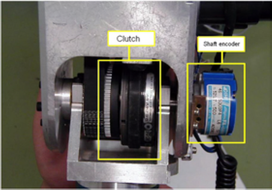
The hybrid joint consists of an electromagnetic clutch between the motor and the output shaft as shown in Fig. 1. The hybrid joint has two exchangeable modes: passive and active mode. When the clutch is released, the joint is free and switched to the passive, and the free link is directly controlled by the coupling characteristics of the manipulator dynamics. When the clutch is on, the link is controlled with the motor.
Hybrid joint
When the external force is applied to the ith link of the arm by a human, or due to the collision with an object in the working environment, the adjacent joint will be switched by the clutch to follow the collision force and the collision link will deform to suppress the impact force. However, the end-effector will be largely deviated from the desired trajectory and task execution ability would be deteriorated. Therefore, we have to introduce the recovery control of the arm to compensate for the deviation. Until now, there has been no method of hybrid joints to control the relation between the manipulator and the contact environment.
Because non-contact sensors, such as vision sensors or proximity sensors, have poor image processing capabilities as well as the ambiguity of detectable volume in proximity-sensing techniques, which makes it difficult to secure a high level of reliability in unexpected collision, we need to develop a method to the extent where H-R contact at its incipient stage can be detected by the contact sensors distributed at the link's surfaces which triggers an earlier response to the robot velocity reduction by commanding the emergency stop and the impact force attenuated by switching the joint's mode. Suppose, now, that an obstacle with constant approaching velocity causes a collision with the manipulator (Fig. 2(a)) and the impulse force F is acting on somewhere of the link i as Fig.2 (a), then, the static relation between the external force F and the joint torques is:

where the Jacobian matrix JF describes the differential relation between the displacement of joint space position and the position of the point AF in which the force F is acting, it is apparent that this force does not influence directly the behavior of the manipulator beyond the link i, therefore, the Jacobian matrix JF has the form:
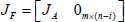
where JA is a m×i matrix associated with the manipulator between the base and the point AF in which the force F is acting, hence, (4) can be rewritten in the form:


(a)External force acting on the arm (left); (b) Collision model (right)
When the ith link make a collision with the object, to intercept the collision force transferring along the ith joint to 1st joint, the ith joint is switched to passive mode. Then the ith joint force torque is equal to zero and the output force of the link to the human is zero. The impulse force can't transfer to the (i−1)th joint by
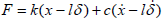
Beside for the hybrid joint, a viscoelastic material should be covered on the arm for absorbing the contact force at the beginning of collision. Therefore, a contact model consisting of the spring-damper and the hybrid joint is studies to produce collision or contact forces during an unexpected collision or contact between a robot body or manipulator and its environment (Fig.2 (b)). Assume a robot arm is constrained on the horizontal plane, after emergency stop and switching joint, for the link using the hybrid joint contacting environment; there will be no torque present in a contact between the robot and the object. Only forces, therefore, are considered. Assume the passive joint can rotate freely, when the collision happens, the hybrid joint is released to separate both collision objects, therefore, no friction between the arm and the object arise. An object comes into collision/contact with a soft surface. The relationship of the collision force, the surface deformation of the robot and the contacting object is given as

where

m is the mass of human, J is the moment of inertia of the link, δ is the displacement angle of the link, x is the deformation of the soft covering, k is the spring coefficient, c is the damp coefficient, l is the distance of the collision point to the joint. The collision force F can be approximately described as:
From (5), we know the collision force is related with the distance l from collision point to adjacent joint. In practice, supposing the arm is redundant enough, if the ith link (i1) itself or l is shorter, in order to attenuate the impulse force, we can set a limit distance llim, if l > llim, the corresponding hybrid joint is switched, that is, the ith joint, otherwise, the jth joint (j ≤ i − 1) is switched to meet the limit distance, the (j+1)th joint is blocked.
Dynamics
Consider n DOF redundant manipulator with the hybrid joints mounted on nonholonomic mobile base and suppose the trajectories of the links are constrained in the horizontal plane, then the links' gravity G(q)=0. The vector of generalized coordinates q may be separated into two sets

with the constraint matrix Av(qv) ∈ Rr×m. Then, the dynamics is:

where [M] ∈ Rn×n is the symmetric and positive definite inertia matrix; [C] ∈ Rn×n is the centrifugal and Coriolis force vector; F represents the external force vector on the arm; qp and qa denote the vector of generalized coordinates of the passive joint and the active joint, respectively. Switching matrix T ∈ Rk×k corresponding to the k hybrid joints is introduced here. This matrix, T is a diagonal matrix and the elements in the matrix are either 0 or 1, if the element Tii = 1, the joint control is set to active mode; whereas it is set to passive mode if Tii = 0. τ v ∈ Rm–r represents the actuated torque vector of the constrained coordinates; Ev ∈ Rm×(m–r represents the input transformation matrix, λ ∈ Rr is the Lanrange multiplier.
Supposing the arm has n joints. If unexpected collision happens to the ith link of the arm, the ith joint is turned into the passive mode, these joints from the (i+1)th joint to the nth joint are blocked. The system has controllable (i−1) joints after collision. If the left active DOF (the number of active joints) of system is more than the DOF of workspace, the manipulator is still redundant. Therefore the arm could be reconfigured to recover the end-effector's position. Otherwise, the mobile base and the arm are cooperated to compensate the end-effector's displacement.
Recovery Control Using Arm
If the manipulator is still redundant after collision, that is, the left active joints in the horizontal plane is more than or equal to 2, we may configurate manipulator to compensate the passive motion of the ith link. The blocked link rotates the ith joint to attenuate the impact force and realize the force following. All the blocked links could be regards as one link, to compensate the position displacement, a dynamic feedback linearization control is adopted (De Luca A. & Oriolo G., 2000). For the page limit, we omit here.
Recovery Control Using Mobile Base
If the number of the arm's active joints meets the following equation:

where nactive is the number of the arm's active joints, nworkspace is the DOF of the workspace. De Luca, Oriolo (2000) solved the problem of the controllability of trajectory to the desired state from any initial state, however, the robot had at least two active joints, i.e., the arm's join number n ≥ 3 (as descripted in 3.2.1). Therefore, in this paper, we will consider the case of the join number n < 3 (that is, n=1 or n=2) and the arm has one underactuted joint. The number of the arm's active joints (the control input) is less than that of workspace.
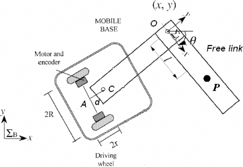
Assume the motion is constrained in 2D environment; then the whole arm is underactuated and demonstrated in Fig.3, where O is the mass centre of the mobile base; the joint O is (x, y) in the base frame; OA is d; φ is the direction angle of the mobile base. Two motion controllers of the translational controller and the rotational controllers extended from the works of Arai and Tanie (1998) are proposed here for controlling the free link. But the difference from Arai and Tanie (1998) is that the motion of the free link is realized with the nonholonomic mobile base.

Mobile manipulator with one free link
The nonholonomic constraint can be represented with the state vector

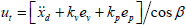
The new input variables (ut, un) for the joint of the free link, that is, the center O in Fig.3, could be expressed as:

where ut is the acceleration component in the x direction of ΣL, and the component, un, normal to it. The vector


where vL, aL and vR aR are the velocities and accelerations of the left wheel and right wheel, respectively.

The coordinates of P point (xp, yp), that is, the center of percussion P, can be represented by the inputs (aL, aR) of the mobile base as:
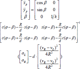
Then it can be transformed from as

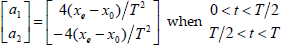
Assuming free link is translation motion along the x-coordinates of ΣB, and the initial and desired configuration of P point at x -axis are x0 and xe. We first plan the trajectory of P point, which composed of the acceleration and deceleration procedure:

for (0 ≤ t ≤ T/2) and (T/2 ≤ t < T) respectively, and T is the time period of the trajectory segment:
where xd denotes the instaneous reference trajectory, then xp is actual trajectory:
where

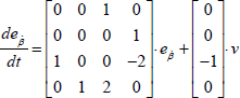
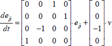
where v is the new input. The converted system is:

where

when the input v is transformed to the input un by (18), yp and β are stabilized to zero.
If the free link is in rotational motion, the input un is given to turn the orientation of the link to follow the desired trajectory:

where β
d
denotes the reference of β on the trajectory,
The P point position error (ex, ey) in the base frame can be represented using (et, en) in the link frame ΣL:

Integrating

when the link rotates with constant velocity
where
When the angular acceleration is considered, and the
where
Give the initial position and the goal position; if the free link has an initial angular velocity, the free arm could be rest with the rotation controller by the input (aL, aR) of mobile base from (21), (24), (25) and then rotate the free link until it is in alignment with the desired position, and then mobile base pushes the free link to the desired position using translation controller by the input (aL, aR) from (17), (18), (19).
If the number of the arm's active joints meets the following equation:

where nactive is the number of the arm's active joints, nworkspace is the DOF of the workspace. The arm has one underactuated link as shown in Fig. 4.
Mobile manipulator with one free link
In this case, we propose a method applying a virtual link fixed on the mobile base. If the desired position is in the workspace of the manipulator, that is, the position can be reached by the rotation of the base and the active link. We treat line CA as a virtual link in Fig. 4. The rotation of mobile base around A is equivalent to one revolve joint. To track the desired position, we make full use of the virtual link CA and the active link CO. The control method as same as Section 3.2.1 is used to complete the position control, and an actuator command

where Ma ∈ R3×3 is the symmetric inertia submatrix of the arm which include the virtual link. C ∈ R2×1 is the centrifugal and Coriolis force vector of the arm. For the virtual joint,
If the desired position is in the workspace of the mobile manipulator, we assume the mobile base is substituted with a virtual link, whose length could be equal to that of the free link and which augments the DOF of the system, and the link is connected to the joint C of the arm with a virtual joint. The trajectory of virtual joint could be regarded as the motion of the mobile base. Therefore, the DOF of the whole system is equal to the DOF of the workspace. This status of the system is similar with Section 3.2.1.
Based on the translational and rotational controllers for the free link in Section 3.2.2, the free link probably has an initial rotation velocity because of switching, the input (ut, un) of active joint C from (17), (18) is utilized to eliminate this angular velocity to rest the free link. Then we recover θ to the desired position (Although θ is changed in eliminating angular velocity of free link). Then, we adopt the above controllers (21), (24), (25) and (17), (18) to complete rotation or translation motion of free link by the mobile base and the left active links. When the mobile base reaches the desired point, we regulate the posture of the mobile base to θ ± π/2. The second step adopts the Section 3.2.1 to complete the motion control.
Hybird Joint Response Experiment
The rapid response of hybrid joint, that is, the time of switching mode, is an important impact factor to achieve the safety for both robot and human, therefore, a shorter time of switching hybrid joint would greatly improve the safety of system. Therefore, we conduct the tests to measure the switching time of the hybrid joint as shown in Fig. 1. The status of hybrid joint is switched from the active mode to passive mode. The releasing time is shown in the Fig.6. The average response time is about 0.045s, if we assume the impact velocity is 0. 5m/s, the deformation of link's surface would be 0.0225m. Therefore, it is better that the thickness of soft covering should be more than 0.05˜0.06m (considering the response time of emergency stop).

Hybrid joint based mobile manipulator.

The switching time of hybrid joint
Assuming we adopt the static/dynamic thresholds of the human pain tolerance limit parameterized by the contact force Flimit=50N in the reference of Yamada's criterion (Yamada, Suita, etc., 1997), and the arm is safe only if the impact velocity is less than about 0.25m/sec in the paper (Yamada, Suita, etc., 1997). We execute the impact simulation with a 3-DOF planar two-wheeled mobile manipulator using the hybrid joints as similar as the Fig. 4. Assume a human collides with the last link. The parameters of the mobile manipulator is m1=3kg; m2=3kg; m3=5kg; l1=1.5m; l2=1m; l3=1m; k=2/3m. The stiffness and damping of the arm covered with the soft materials and the human are selected as k=800N.m−1, c=100N.s.m−1. The human's mass is 50kg, and the maximum impulse velocity of the obstacle could reach to 0.5m/s under the Flimit=50N. The evolutions of the impact forces on the different collision points of last link are shown in Fig. 7.
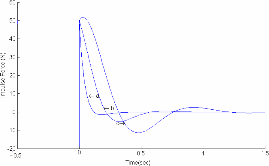
The profile of contact force (blue line) when object collisions with third link, (a): collision point is 0.3m relative to the passive joint; (b): collision point is 0.5m relative to the passive joint; (c):collision point is 0.7m relative to the passive joint. The human veolcity is 0.5m/s.
The impact experiments have been done using the hybrid joints in mobile manipulator as shown Fig. 5. The arm is with the hybrid joint and covered with a soft covering, whose spring and damper are selected respectively as k=800N·m−1, c=100N·s·m−1. To confirm our objectives for simplicity, the impact experiments are conducted using the rigid arm with the hybrid joint. The experiment condition is similar with experiment 1, but the fifth joint equipped with hybrid joint of the arm causes an unexpected collision with the human in approximately constant velocity 0.5m/s. The collision point on the link is 0.3m from the joint. The parameters of the collision link of the arm is M=5kg (the fifth link), L=0.3m (the fifth's length), and the collision point is 0.3m to the joint. The contact forces are measured with the force/torque sensor attached to the contacted link of the arm.
For the experiment, the link has an initial velocity about 0.2rad/s. When the collision takes place, the trigger on the link is contacted, the system commands the emergency stop and then the circuit releases the hybrid joint, the response of collision force is shown in Fig. 8, which shows that the contact force is remarkably attenuated, damped more quickly and lasts shorter time compared with the previous works of Lim, Tanie (1999) and Yoon, Kang, etc. (2003). But the collision experiment result is a little different from the simulations because they are executed in the ideal situation where no external disturbances (including the friction and unmodeled dynamics, etc) have been considered. Therefore, the hardware experiments prove that mechanism is effective.
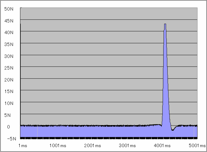
Contact force of the experiment with soft covering and hybrid joint (down)
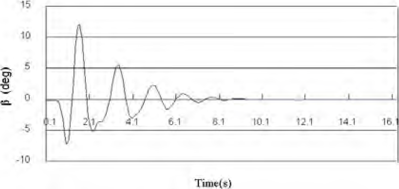
For the mobile manipulator we make experiments as shown in Fig.5, we use the mobile base to realize the recover control. The length of the free link is 0.3m and its mass is 5kg, k=0.185m. The free joint is 87.2cm relative to the center of the mobile base. The initial Angle 0.1351 rad with zero velocity, the desired goal angle is 0 rad. On the time t=1.7s, an impact force is put on the link, and then the link is with an angular velocity. The rotation angle and the angular velocity of free link under control are shown in the Fig.9, and after 20s, it approaches the desired angle. The trajectory of the mobile base is shown in Fig.10 and the final position is (4.155cm, −1.1126cm). Then, the mobile base turns around the center, and makes the direction angle align with the free link. The translation of free link with the mobile base goes on. The expected motion of the free link is to translate the passive link along the y-axis from (0cm, 87.2cm,) to the position (0cm, 127.2cm), but the initial position of the passive joint is (9.47cm, 87. 2cm, 0°), that is, we need to eliminate the x-coordinate error to 0 cm and keep the displacement angle of the free link to 0 rad. The both control errors results are shown in Fig.11 and Fig.12. And the corresponding trajectory of the mobile base is demonstrated in Fig. 13. Due to the movement error of the mobile base, the position of the mobile base only arrives the (–0.219cm, 40.6cm), but the end-effector has arrived the position (–0.219cm, 127.8cm, 0°) in the tolerant error.

The rotation of passive link, the desired angle β is 0 rad.

The trajectory of mobile base for the rotation β
Angle of the passive link by the mobile base, the desired β is 0 rad.

Error of the passive joint, the desired x coordinate is 0m.

The trajectory of mobile base for the translation
A hybrid joint scheme has been suggested in order to assure the safe interaction in human-robot cooperative tasks. During an unexpected collision between the robot and human, the suppression of collision/contact forces has been investigated using the hybrid joints, and the control laws for the restoration of desired position have also been developed. Validity of the proposed mechanism and control strategy has been verified by simulation and experimental tests.