
Abstract
The main purpose of this work was to show that by using low-pressure plasma it is possible to obtain platinum nanoparticles with uniform size and shape and then apply these nanoparticles in order to evaluate the process efficiency. For this a platinum coil wire was placed in an aluminium mould at approximately 10mm from an electrode. The aluminium mould was made with an aperture immediately under the platinum coil. This way the particles released by the plasma action were directed towards the polymeric membrane. Chemical activity tests were performed in commercially produced cells in order to compare the efficiency of these and those produced by plasma. The results showed a voltage of 1.0V for the commercially produced membrane and 950mV for the membrane processed by plasma. The chemical activity test showed low efficiency for the cell produced by plasma when compared to the commercial cell; however it is worth noting that the amount of carbon support is far smaller than in the commercial cell, which means that if the support is increased, the efficiency can also be increased.
1. Introduction
Nano-structured materials are materials and/or particles that have two or more dimensions with 100 nanometres or less. The properties of many conventional materials are changed when nanoparticles are formed. This is typically because nanoparticles have a greater surface area per unit weight than thin films or large particles. This causes them to be more reactive to certain molecules. Reactive materials are of special interest in chemical analyses, catalyzes and energy conversion, etc. [1]. Platinum nanoparticles are sub-micrometre-sized particles of platinum and their applications are found in many areas of technology like medicine, renewable energies, sensors, etc. The use of nanoparticles increases the efficiency and reduces the cost of these materials. Platinum is the main material used in catalytic processes, but it is an expensive material and due to its intense use may become increasingly rare. Efforts have been made to find different ways of reducing the amount of platinum used without reducing its efficiency. Low-pressure plasma has several applications in technological areas, such as micro-devices, microelectronics MEMS (Micro-Electro Mechanical System) fabrication, material processing, and now in nanotechnology areas. Obtaining nanoparticles by plasma at low pressures has been studied mainly with respect to the platinum nanoparticles for use in fuel cells [2, 3]. Catalytic platinum layers may be obtained by thermal evaporation or electrochemical deposition, but contamination reduces the efficiency of the operation. The better quality layers are obtained by RF sputtering; however, this process is very expensive and uses pure platinum as a target and gases such as oxygen, hydrogen, etc. to achieve nanoparticle formation. In this case, the nanoparticles depend on the quality of the surface, roughness, porosity and other surface energy [2, 4]. A sputtering technique can provide very good results and can also be done through plasma polymerization. Therefore, it is possible to control the metal in the film, as well as having a more homogeneous dispersion and better control of particle size [12, 13]. Due to its high resistance to corrosion and oxidation, high melting point, electrical conductivity and catalytic activity, platinum has been widely used in many applications especially as a catalyzer for CO oxidation in catalytic converters and for fuel cell technologies [5, 6]. Platinum is the base of catalyzers in engines and fuel cells. In fuel cells, platinum is widely used as a catalyzer, but when used alone it proves ineffective. It requires high potencies for a current density to be achieved [5, 6]. This is due to the chemical interaction of organic molecules with the platinum surface, which is quite strong, so that dissociative chemical adsorption occurs, which forms strongly adsorbed species that end up blocking the active sites of the electrode [7]. The quantity of Pt applied in the process is a problem, as this is an expensive material. Thus, studies have been developed to reduce the amount of Pt required, in addition to stimulating the development of new methods of nanometric catalysis [3, 6, 7, 8]. This is achieved through methods such as the use of platinum clusters at a nanoscale to improve the catalytic activity per mass of platinum, due to the high surface area in proportion to volume and therefore, reduce the amount of expensive metal applied [3, 7, 8, 9, 10, 11]. Recent studies have been developed in high surfaces of porous carbon dispersal matrixes [12, 13]. Carbon supports have become the one of most vastly researched materials because of their applications in all aspects of nanotechnology [13, 14, 15]. The controlled coating of metal nanoparticles onto carbon nanotubes without the aggregation of these particles is crucial and must be researched [14]. Several methods have been successfully developed and practically applied. For example, nanocomposites, formed from depositing platinum nanocrystals onto carbon nanotubes, play an important role in fuel cell application, fabricating electrochemical sensors and in many other areas [14, 15].
2. Experiments
In this study, we used a reactive ion etching with parallel plates to obtain the plasma (Fig. 1). The membrane used was a Nafion® membrane with dimensions of 50×50mm and the area to deposit catalyzers was 25×25mm. Platinum nanoparticles have been extracted from a platinum wire with a purity rate of 99.98%. This platinum wire was coiled in five turns separated by approximately 10mm. In order to have the film deposited only on the useful area of the membrane, an aluminium mould was made with the total size of the membrane and in the middle an aperture of corresponding size to the useful area of the cell was created.

Schematic of the platinum wire disposition inside of the chamber
The platinum coil was connected over the aperture of the aluminium mould. The membrane was placed on the electrode and then the aluminium mould was placed over it (Fig. 1). A cooling water circuit was connected to the electrode in order to maintain the electrode temperature near to room temperature and thereby prevent potential damage to the membrane due to high temperatures in the plasma. Then the chamber was closed and the system evacuated to a pressure of about 1mTorr.
Firstly, carbon was deposited using methane gas with purity of 99.5%, pressure of 300mTorr, flow of 200sccm, power of 200 watts and time of five minutes on both sides. Then the aluminium mould with a platinum coil was inserted in the chamber for platinum nanoparticle deposition. For this deposition argon gas with 99.999% purity, pressure of 500mTorr, 45sccm flow, power of 100 Watts and 30 seconds time were also used on both sides.
After deposition, the membranes were hydrated and activated with a 30% hydrogen peroxide solution, distilled water and a 10% sulphuric acid solution for one hour each. Then the membranes were mounted on the cell and measurements of voltage and current were made.
A commercial membrane produced by a TDM Fuel cell was used for voltage and current comparison.
The chemical activity tests were made using the commercial membrane and Nafion with nanoparticles produced by a plasma technique.
The following were used in these tests: hydrogen (99.995% purity) and oxygen (99.99% purity). These gases were hydrated through a humidifier system using deionized water at 18MOhms. The hydrogen pressure was 3.5 bar and flowed at 17sccm, while the oxygen pressure was 1 bar and the flow was 25sccm. The water flow to maintain hydration was 1.5 l/h at 30
The assembly of the system for chemical activity test was as follows: the gas cylinders (hydrogen and oxygen) were connected to mass flow controllers (MFC,), which in turn were connected to a humidifier containing deionized water, which was in turn connected to the fuel cell (Fig. 2). Thus, not only did it keep the moisture of the gas, it also kept the cell hydrated by a water drag system. Through MFC and pressure regulators these parameters could be maintained at a constant level during the chemical activity test.
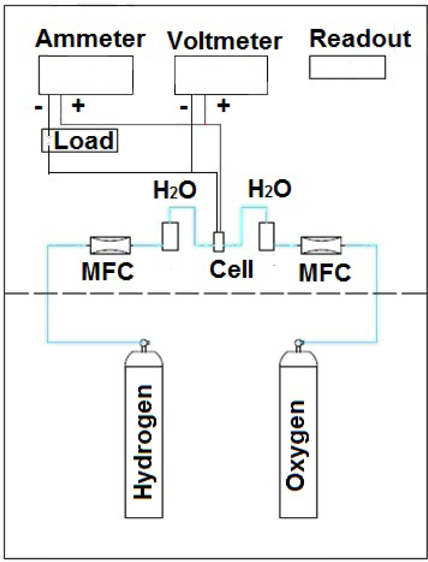
Schematic of fuel cell chemical activity test
To measure the voltage and current a voltmeter and an ammeter were used. The voltmeter was connected to the ammeter in parallel to the fuel cell and the ammeter was connected in series with the load fuel cell.
Empyrean x-ray equipment was used from Panalytical to identify the platinum on polymeric membranes and SEM – FEG model Nova NanoSEM400 from FEI was used for platinum image detection.
The plasma technique allows control of all the parameters of the process and through this technique it is possible to develop processes able to produce particles of several sizes and shapes depending on the applied parameters and in this way control the physical properties of the particles produced.
The main objective of this work was to develop platinum nanoparticles with homogeneous shape and size in order to reduce the amount of platinum used in fuel cell devices.
3. Results and discussion
By using SEM analyses it was possible to observe the size of the platinum nanoparticles deposited by the plasma technique and then to compare them with the platinum nanoparticles produced commercially (Fig. 3 and 4).
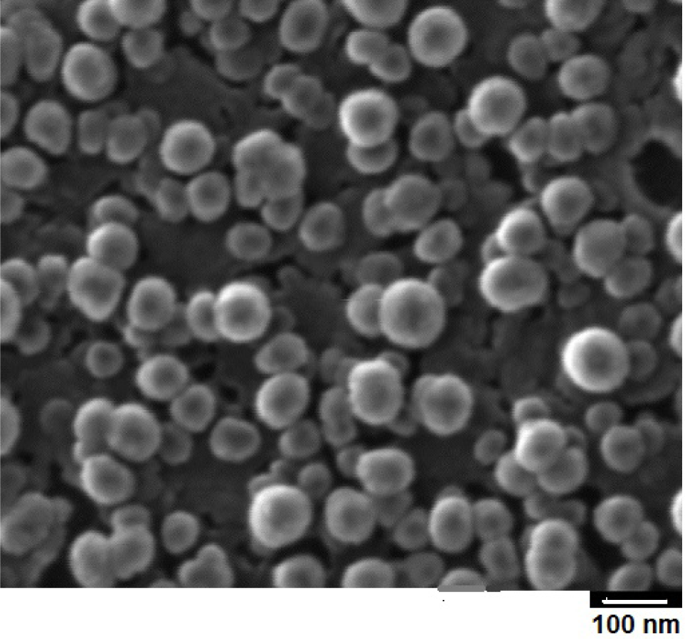
SEM image-Platinum nanoparticles produced by plasma technique

SEM Image – Platinum nanoparticle commercial by TDM Fuel cell
Figure 3 shows the uniformity of size and shape after the plasma deposition. The particles are scattered on the carbon film showing a small amount of platinum nanoparticles deposited.
In this image it is possible to determine the number of platinum nanoparticles deposited in the work area of fuel cells. In this way we find the value of 34×104 platinum particles per cm2. By comparison, the commercial fuel cell has a larger number of platinum nanoparticles than the membrane produced by the plasma technique.
The chemical activity tests show interesting results as they indicate that the nanoparticles produced by the plasma technique, even though smaller in number than the commercial membrane, show similar voltage values. While for commercial fuel cells the voltage value is around 1.0V (for fuel cells produced by plasma, it was 950mV). Figure 5 shows the comparison of the performance between a commercial cell and a processed cell. The low performance can be explained due to the commercial cell having four times more platinum than he processed cell. Furthermore, the commercial cell has a thicker carbon support layer.
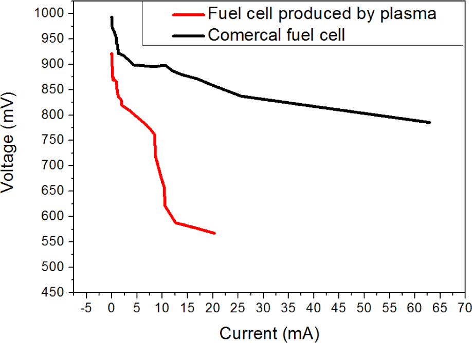
Polarization curve showing the comparison of efficiency values for commercial cells and plasma technique processed cells.
In the graphic it is possible to see that the commercial membrane voltage does not decrease bellow 800mV when the short circuit current reaches the maximum, showing a good performance. Compared with the processed cell, it is possible to see that the voltage decreases below 600mV with around 20mA for the short circuit current; in other words, the performance is three times smaller than the commercial membrane. The most noticeable difference between both cells and the possible reason for the low efficiency of the processed cell may be the carbon layer. The carbon support of the commercial membrane was about 1mm, causing the gas to flow easily, while the Nafion® membrane had about 500 nanometres of carbon.
The total efficiency of the cell can be observed from a graphical analysis of power versus current, where the maximum power is determined for the short circuit current (Fig 6).

Graphic of power versus current comparing values for commercial and plasma technique processed membranes.
Although the total efficiency obtained on the processed membranes by plasma was smaller than the commercial membranes, the curves follow the same pattern. The chart shows the maximum power for the maximum current in a linear path. For the processed cell it is possible to observe a deviation of 10mA, caused by a hydration problem during the measurement.
The current and voltage measures are important in order to determine whether the membrane suffered any damage during the plasma process due to low pressure inside the chamber, low humidity, ionic bombardment or temperature. The curves obtained by chemical activity tests showed that the membrane did not suffer any changes in its physical and chemical properties and that the electric characteristics were very similar.
On the other hand, the hydration required to maintain the humidity of the cell was not necessary for the commercial membrane, while for the membrane processed by plasma, the oxygen had to be humidified with steam and fluxed inside the cell. Therefore, the results were more reliable and stable during all measurements.
With the x-ray equipment it was possible to identify the platinum on the polymeric membrane (Fig. 7). The purpose of this technique was to verify if any other material could contaminate the fuel cell in the process of plasma system construction, such as aluminium or iron. Fortunately, the amount of these particles was insignificant compared to the platinum nanoparticles. In the graphic, it is possible to easily see the platinum peak, while other peaks do not appear, showing that the material used for chamber construction is not deposited on the substrate on a large scale and does not affect it.

X-ray analyse for platinum detection on polymeric membrane after plasma process.
4. Conclusions
By using Low Pressure Plasma techniques it is possible to obtain platinum nanoparticles directly on a polymeric membrane, without this membrane suffering any change in its physicochemical properties due to the plasma action. Platinum nanoparticles obtained by plasma, have homogeneous size and shape, which suggests that less catalyzer is required to achieve the same level of efficiency than a commercial cell, which has larger dimensions and does not have the homogeneity of nanoparticles. Thus the amount of platinum to be used is decreased, (saving the material).
It is also possible to use other materials, such as nickel [1] for example, which can be processed by plasma together with platinum to increase the efficiency of the cell. This would further reduce the amount of platinum used.
Optimization for the preparation of this membrane is also a factor to be considered, since depositions are performed in short times and directly on the membrane.
Footnotes
5. Acknowledgements
The authors thank FAPESP and CNPQ for the financial support, LSI for providing all infrastructure and the technicians, Alexandre Marques Camponucci, Rubens Pereira and Julio Cesar dos Santos for technical support.