
Abstract
In this study, analytical techniques and fuzzy logic methods are applied to the dynamic modelling and efficient swimming control of a biomimetic robotic fish, which is actuated by an ionic polymer-metal composite (IPMC). A physical-based model for the biomimetic robotic fish is proposed. The model incorporates both the hydrodynamics of the IPMC tail and the actuation dynamics of the IPMC. The comparison of the results of the simulations and experiments shows the feasibility of the dynamic model. By using this model, we found that the harmonic control of the actuation frequency and voltage amplitude of the IPMC is a principal mechanism through which the robotic fish can obtain high thrust efficiency while swimming. The fuzzy control method, which is based on the knowledge of the IPMC fish's dynamic behaviour, successfully utilized this principal mechanism. By comparing the thrust performance of the robotic fish with other control methods via simulation, we established that the fuzzy controller was able to achieve faster acceleration compared with what could be achieved with a conventional PID controller. The thrust efficiency during a steady state was superior to that with conventional control methods. We also found that when using the fuzzy control method the robotic fish can always swim near a higher actuation frequency, which could obtain both the desired speed and high thrust efficiency.
1. Introduction
Many biomimetic underwater robots have been developed and used in various fields [1, 2]. As indicated by Habib, smart materials are the foundation supporting the development of new biomimetic based technology [3–4]. The use of smart materials has significantly contributed to the development of biomimetic underwater robots and micro-robots [5–9]. Ionic polymer-metal composites (IPMCs) are innovative materials made of an ionic polymer membrane with chemically plated gold or platinum as electrodes on both sides [10, 11] (see Figure 1). Deformation will occur if an electric field is applied across them, which causes the ions to redistribute. On the other hand, they generate a detectable voltage if subjected to a mechanical deformation. Briefly, they have the advantages of low activation voltage actuation (1-2V), limited power consumption, low noise and high flexibility. Therefore, IPMCs provide the possibility of developing a low-noise, micro-size, flexible biomimetic underwater robot. Plenty of studies on IPMC swimmers have been reported in recent years, such as robotic rajiformes, robotic fish, snake-like robots, etc. [12–15]. However, the current control of the IPMC fish is based on the simple application of the IPMC's characteristics, which would lead to imperfect results in thrust performance. The current research presented here aims to investigate how biomimetic IPMC robotic fish can swim efficiently in water. Existing prior research relevant to the materials is presented here, and the current contributions can be broadly classified into two categories: dynamic modelling and control methods for robotic fish.
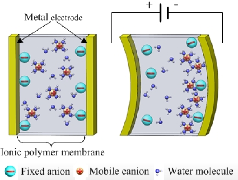
Illustration of the IPMC operating principle.
1.1 Dynamic modelling
For the optimal design and control of an IPMC swimmer, an effective model is desired. Kim proposed an analytical framework of the modelling of the dynamic characteristics of single or multi-segment IPMC actuators for aquatic propulsor applications [16]. A speed model for IPMC-propelled robotic fish that captures the complex hydrodynamic interactions between IPMCs and fluids was presented by Tan and Porfiri [17–20]. The impedance model was also developed and used to predict the bending moment of actuated IPMCs [21]. To date, few studies have reported the thrust efficiency of IPMC-actuated underwater robots.
In this paper, a thrust efficiency model for IPMC-actuated robotic fish is proposed and the model is validated in experiments using a biomimetic IPMC-actuated robotic fish fixed on a servo towing system. Based on the work from [18], the hydrodynamic force on the passive fin is considered, which will influence the IPMC bending moment at each instant. The elongate-body theory of Lighthill is applied to predict the actuated vibrating IPMC's thrust performance in the swimming robot [22].
The IPMC fish was experimentally tested by both swimming freely in the water and being dragged under the servo towing system. The thrust force, forward speed and power consumption of the robotic fish were investigated by hydrodynamic experiments under self-propelled conditions. The thrust efficiency of the robotic fish was derived through the presented data. The experimental and simulation results were compared to validate the theoretical model.
1.2 Control methods
When applied to the control of IPMC fish, previous research on motion control has mainly focused on the open-loop method for swimming performance [8, 23–24]. The open-loop method has usually applied direct control to the IPMC. However, the open-loop control method can neither help the robotic fish achieve the desired speed nor obtain high swimming efficiency, since there is no speed feedback. The model-based closed-loop method used extremum seeking feedback to control the vibration of the IPMC tail, which consists of two IPMC stripes as an actuator and a sensor [25]. However, the thrust performance of the IPMC tail was not studied experimentally. Furthermore, the fuzzy control method has been credited in various applications as a powerful tool capable of providing controllers for uncertainties and systems with nonlinear dynamics [26–29]. This has recently been applied to the control of tail fin and pectoral fin biomimetic systems [30–31], and the results suggest that fuzzy logic control is highly suitable for the motion control of robotic fish. Previously, the authors have applied the fuzzy control method to the efficient swimming of a robotic fish [32]. However, there are few studies on the control methods of IPMC-actuated swimmers that take their thrust efficiency - which is the most important metric for the swimming performance of a robotic fish - into consideration. It should be noted that thrust efficiency is one of the most attractive aspects of micro underwater robots, as its energy capacity is limited.
Considering the merits and shortcomings of previous control methods for making IPMC robotic fish swim efficiently and controllably, in this study we propose to implement a fuzzy control method based on hydrodynamic knowledge to make an IPMC fish swim efficiently. The results are compared with those of the classical proportional–integral-derivative (PID) controller.
This paper is organized as follows. The robotic fish is described in Section 2. The dynamic model is presented in Section 3. The experimental results and a comparison with the model prediction are presented in Section 4.
Section 5 provides the control methods. The conclusion is shown in Section 6.
2. Description of the IPMC robotic fish
Figure 2 shows the robotic fish for the study. The robotic fish consists of a rigid body and an IPMC caudal fin. The body shell is made of nylon plastics and covered with a black matt resin varnish. Its shape was designed according to the body proportion of a yellow croaker (Pseudosciaena crocea) to make the body streamlined. The tail is attached to the body by small rectangular conductive copper plates acting as a clamp. The fin is added to the end of the IPMC to increase propulsion.

Prototype of the robotic fish.
The batteries (two 3.7 V in series) and the electronics are placed in the interior space of the shell, where the components are protected from the water. Inspired by the motor design, the control of the IPMC is based on a Hbridge utilizing L298N, which enables convenient I/O control and a large current. A counterweight is put in the bottom of the fish to achieve neutral buoyancy and enhance the roll and pitch stability. Furthermore, a connector is set on top of the fish to attach it to the servo towing system. The robotic fish is experimentally studied, both for swimming in the water and on the servo towing system under self-propelled conditions. Without the tail, the fish is 144 mm in length, 52.5 mm in height and 37.5 mm at its widest point. The total weight of the robotic fish is approximately 180 g, which is the same as that of a yellow croaker of the same size.
3. Dynamic modelling of the robotic fish's thrust efficiency
In this section, the main goal is to understand the interactions between IPMC's power consumption and the thrust that the IPMC produces in the water. The IPMC-bending model and impendence model are introduced. By combing Lighthill's theory on slender body and the dynamics with a passive fin in the water, the model for predicting the efficiency of the IPMC-propelled robotic fish is achieved.
3.1 IPMC beam electrical impendence model and actuation model in the water
Nemat-Nasser and Li first proposed a model that describes mechanoelectrical transduction considering electrostatic interactions within a polymer [33]. The underlying cause of actuation is explained by the internal stress induced by the interaction between ion pairs inside a cluster. Chen and Tan investigated the electrical dynamics of IPMCs based on Nemat-Nasser's work [21]. They expanded the model and added the effect of surface resistance. The model is represented as an infinite-dimensional transfer function relating the bending displacement w(z,s) to the applied voltage V(s). Consider Figure 3, where the IPMC beam is clamped at one end (z = 0) and is subject to an actuation voltage producing the tip displacement w(t) at the other end (z = L).

Geometric definitions for the model of the IPMC.
The transfer function H1(z,s) relating w(z,s) to V(s) is shown as:

with:

where α0, r1, r2, κ e , R, T, ΔV, d, Ye, F, C−, Rp, ωn and ξ are the physical constants defined in [21]. W, L and h are the width, length and half thickness of the IPMC beam defined in Figure 3 and I=2Wh3/3 is the inertial moment of the IPMC beam.
The transfer function for the impedance model can be shown as:

where:

Mbemmo et al. have proposed a model for an IPMC-propelled robotic fish [18]. In it, a passive plastic fin is attached to the IPMC beam which incorporates both IPMC actuation dynamics and hydrodynamics, as well as the interactions between the plastic fin and the IPMC actuator. The model relates the bending displacement and the slope at z = L' to the voltage input V(s), as follows:

The expression of H2, H2d and D can be found in [18].
3.2 Efficiency model of the IPMC fish
Lighthill's slender theory applies to those fish or swimming mammals whose cross-sections gradually vary along their lengths and change slowly [22]. The robotic fish in Section 2 is thus slender and is applicable to Lighthill's theory. In the steady state, the fish will achieve a periodic, forward motion at the speed Usim. Given the input voltage V(t) = Asin(ωt) from [17], one can find Usim as:
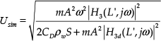
where S is the characteristic cross-sectional area of the fish body, CD is the drag coefficient and ρw denotes the density of the water. m is the virtual mass density at z = L, expressed as m = πS2cρwβ/4 (the details can be found in [22]).
The swimming efficiency of a real fish is defined as the ratio of the actual power (contributed to the propulsion) to the total amount of the power consumed by the fish [34]. In robotics, there is a similar measure of swimming efficiency, which is defined by the ratio between useful power (output) and the total power input [35]. The propulsive efficiency η is defined as:

The power consumption of the IPMC under the input voltage V(t) = Asin(ωt) is written as:

where Z can be derived by Eq. (2). According to Eq. (5) and Eq. (6), the efficiency of an IPMC fish actuated under a sinusoidal wave voltage with an amplitude A can be obtained as:

The speed Usim is obtained in Eq. (4).
4. Identification of the parameters and experimental results
In this section, we identified the parameters of the model and tested the thrust efficiency of the IPMC fish and compared the experimental data with the simulation results of the theoretical model. The thrust efficiency η exp is expressed as:

As such, the thrust Texp, speed Uexp and power consumption Pexp is what would be measured to obtain the experimental results of the thrust efficiency. A series of experiments were conducted in a towing system and a water tank, as shown in subsection 4.1. The parameters of the IPMC actuation model are identified in subsection 4.2. We will introduce the measurement method and results of Uexp, Texp and Pexp in subsection 4.3. Subsection 4.4 provides the final derivation of the thrust efficiency η exp .
4.1 Experimental setup
Hydrodynamic experiments were conducted in a horizontal low-velocity servo towing system to ascertain the thrust efficiency and thrust coefficient of the fish body in free stream conditions. This servo towing system, driven by the 4,000 W AC motor, has been used previously for the purpose of obtaining the quantitative hydrodynamics of a self-propelled underwater robot [36–39]. The water tunnel has a running speed range from 0.005 to 1 m/s, and the uniformity of the flow velocity is 0.2%.
Figure 4 shows the mechanical components of the experimental apparatus, where the robotic fish and its affiliated components are fixed under a component force transducer that is attached to the carriage by screws. The robotic fish is submerged underwater, while its transmission mechanism is mounted on a metal plate and is above the surface of the water. The external force of the robotic fish is measured using a force transducer (CFBLSM, BGTSE Inc., China), which is assembled vertically above the robotic fish model and has a measuring range of 1 N and a sensitivity of 0.01 N in the axial direction. The thrust produced by the fish is enlarged through the mast by about 100 times, according to the moment theory. The centre of mass G of the fish is set right under the mast to minimize the influence of gravity during the experimental process.
The control unit and power supply of the robotic fish are both mounted on a carriage rest, which is belt-driven on rails that run along the towing direction (the forward direction). The water tank - which is 7.8 m × 1.2 m × 1.1 m - is filled with water and provides the robotic model with sufficient space to move without being affected by the boundaries on both sides. The fish is also located at middepth in the tank so as to avoid any interference effects from the free surface and the bottom of the tank.
4.2 IPMC model verification
The IPMC used in this experiment, and also adopted as the propulsive element on the fish-like robot, is based on Nafion N117 and was procured from Environmental Robots (www.environmental-robots.com). In this paper, an IPMC actuator of 6.2 × 26.6 mm in size and 0.35 mm in thickness was tested. The IPMC sample was stored in deionized water for twelve hours before the experiments. The IPMC beam was clamped at one end. A signal generator (YX1620P, Yangzhong Pioneer Electronics Co., China) with a power amplifier provided the actuation sinusoidal signals with an amplitude of 3.3 V and a frequency from 0.1 to 20 Hz. The oscillation of the IPMC beam was measured by a laser sensor (OADM 20U2441/S14C, Baumer Inc., Switzerland). A data recorder (Nicolet Vision XP, LDS Inc., Germany) was used to record the experimental results, which had 16 sampling channels and a maximum sampling rate of 100 kHz. Based upon the actuation response of the IPMC beam, one can measure the magnitude and phase response of the actuator at a frequency f. In this paper, the maximum deflection of the IPMC was 7 mm in the air with an applied sinusoidal actuation signal amplitude of 3.3 V and a frequency of 7 Hz. It was noticed that the IPMC at low frequency showed an overall deflection during the cycle, and no limitation of the bending performance was noticed. Table 1 lists the parameters obtained for the IPMC actuation model and efficiency model, which are identified through curve-fitting utilizing MATLAB (http://www.mathworks.com/). Figure 6 shows that the magnitude gain and phase shift of the actuation model are in good agreement with the experimental results.

Experimental setup: (a) Illustration of the thrust measurement system; (b) Snapshot of the water tunnel and the fish thrust measurement system.
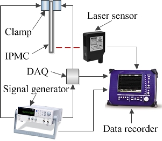
The experimental setup for the identification of the IPMC model.
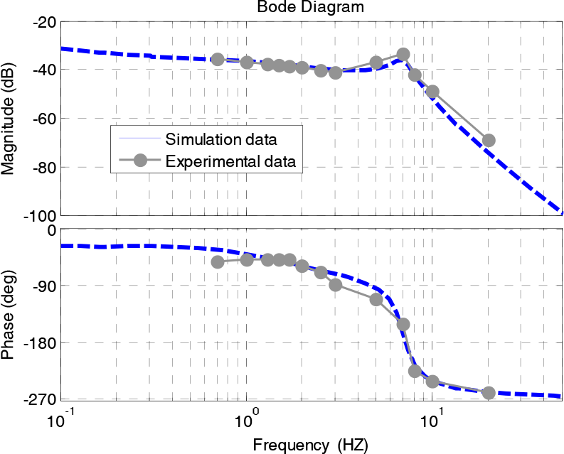
Comparison of IPMC actuation response with actuation model predictions.
Parameters for the IPMC actuation model and efficiency model.

4.3 Speed, thrust force and power measurement
To validate the efficiency model of the robotic fish, the speed, power consumption and thrust of the fish propelled by the IPMC were measured. In this experiment, the robotic fish propelled by the IPMC tail swam freely in a water tank marked with start and finish lines. By recording the time the fish took to travel through a given range - which is 10 cm when its speed reaches the steady state - the speed is measured. Figure 7 shows the comparison of the experimental speed data with the model prediction (see Eq. (4)), where the robotic fish is under sinusoidal wave voltage inputs with an amplitude of 3.3 V and different frequencies, from 0.7 Hz to 2.8 Hz. There is an optimal frequency for speed of approximately 1.5 Hz under which the fish reaches the highest speed. As the actuation frequency is relatively high or low, the speed of the IPMC fish decreases, which has good agreement with the experimental results in [18, 20].
To measure the power consumption and thrust, a series of experiments were conducted in the servo towing tank. The thrust of the fish propelled by the IPMC was measured. The fish was dragged under the servo towing system at the cruising speed obtained from the free swimming test above. At each cruising speed Uexp, the IPMC was under the corresponding input voltage shown in Figure 7. The force sensor fixed above the robotic fish was used to detect the external force T acting on the fish. One found that the measured external force T was almost equal to zero, since the thrust Texp produced by the IPMC tail was equal to the drag force FD at a speed Uexp. According to Newton's law, one can consider that the robotic fish was swimming in the water freely without any external force acting on it from the apparatus above when the detected force T = FD - Texp = 0. Next, the fish was dragged at the same speed Uexp without the IPMC vibrating to obtain just the drag force FD. As a result, the thrust Texp of the IPMC for different frequencies could be found to be Texp = FD.
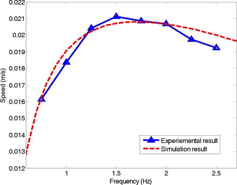
Comparison of the experimental speed data with the model prediction.
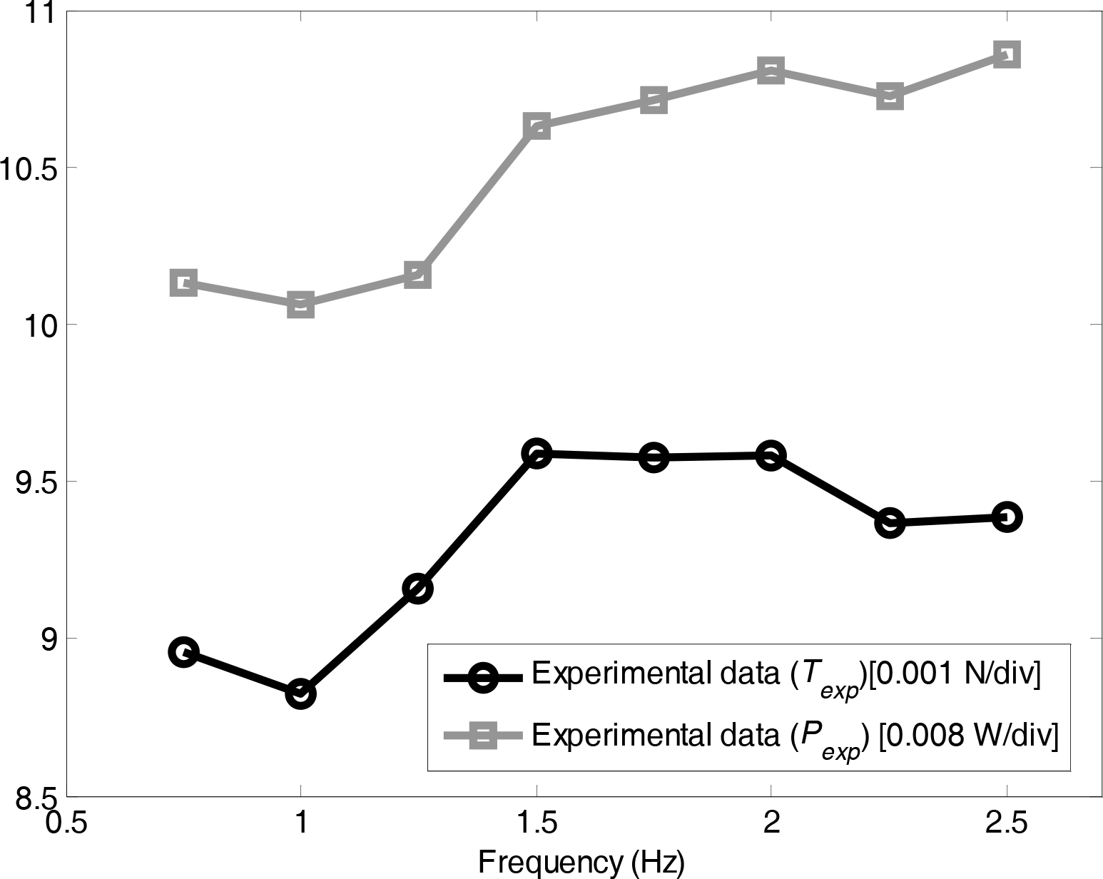
The data recorder was used to measure the force as well as the input voltage Vexp and the output current Iexp of the IPMC tail simultaneously. The power consumption Pexp can be obtained:
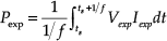
where ts is a random point in time during its performance and f is the operating frequency. The IPMC tail was tested at a frequency ranging from 0.5 Hz to 3 Hz.
Robotic fish power consumption and thrust force during swimming.
Figure 8 shows the measured experimental thrust force and power consumption of the IPMC fish. The thrust produced by the IPMC tail reaches its maximum when the frequency approximates 1.5 Hz, which has good agreement with the speed of the IPMC fish. It is also noticed that as the operating frequency increases, the power consumption of the IPMC increases.
The drag coefficient CD is a significant parameter in the model. It is related to the fish body, which depends on the Reynolds number, the fitness ratio of the body and the properties of the fish surface. The drag force is defined as [22]:
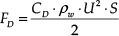
In order to identify CD, the fish was dragged at different velocities, from 0.005 m/s to 0.1 m/s, and the force sensor was used to measure the drag force. With the measured drag force FD, velocity U and wetted surface area of the fish S, which was 0.0173 m2, the drag coefficient CD was derived as CD = 0.095.
4.4 Thrust efficiency
Based on the measured thrust Texp, speed Uexp and power consumption Pexp, and with Eq. (8), the experimental data of the IPMC fish efficiency η exp was achieved.
The capability of the model in predicting efficiency was verified for different operating frequencies. Figure 9 shows that the predicted model η sim matches well with the experimental data η exp . It can be seen that, inceptively, the efficiency increases with the increase of the frequency, and when the frequency is relatively high, the efficiency decreases. Its thrust efficiency reaches its maximum when the frequency is approximately 1.5 Hz. The model can predict the thrust efficiency of the IPMC fish well and provides the principle for the optimal design and control of the high efficiency robotic fish propelled by an IPMC.
The voltage amplitude A is another control input of the IPMC fish which should be added to the control of it. As indicated by Porfiri [20], the input voltage has a roughly linear correlation with the speed. Figure 10 shows a 3D plot giving the simulation speed results with varied voltage amplitudes and actuation frequencies, which indicates good agreement with the results in [20]. As we can see, the speed could be raised as the input voltage increases under the same actuation frequency. Figure 11 gives a 3D plot showing the simulation results of the thrust efficiency with varied voltage amplitudes and actuation frequencies. It is interesting that when the voltage amplitude is relatively high, the thrust efficiency decreases. To achieve the optimal control input (frequency f and amplitude A) for efficient swimming, an intelligent controller is needed for the IPMC fish.

Comparison of the experimental thrust efficiency data with the model prediction.
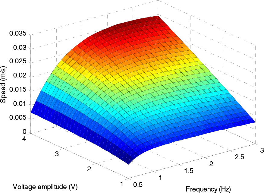
A 3D plot showing the simulation speed result with varied voltage amplitudes and actuation frequencies.

A 3D plot showing the simulation thrust efficiency result with varied voltage amplitudes and actuation frequencies.
5. Efficient swimming control methods and results
In this section, the implementation and simulation results for the swimming speed and thrust efficiency of the robotic fish using a fuzzy logic controller will be proposed and compared. In addition, a PID controller - which is widely used in industry because of its simple structure - is also used for comparison. We applied genetic algorithms (GAs) for optimizing the parameters of the PID as an offline step. Next, we used the parameters for the PID control and compared the results with those of the fuzzy control.
5.1 Design of a classical PID controller
First, we introduce the PID controller's fundamentals [40–41]. Conventional PID controllers were applied to IPMC fish control. It should be noted that the control variable of the IPMC is the actuation frequency and voltage amplitude [42]. We recall that, in previous studies on other robotic fish controls, the control variable is usually the flapping frequency with the slope angle fixed [6, 43]. In the current PID controller, the sinusoid voltage amplitude will be fixed at 3.3 V and the desired speed will be realized by changing the frequency f. The conventional PID controller in its discrete form can be characterized by:
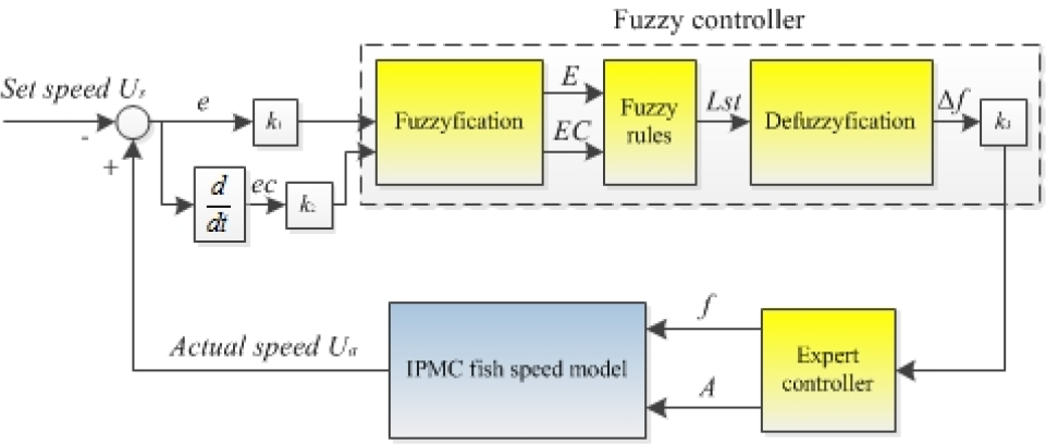
where k is a discrete time instant, δf (k) is the output frequency deviation at a certain instant, and kp, ki and kd are defined as proportional, integral and derivative gains. e(k) and δe(k) are the speed error terms at a certain time instant and δe(k) denotes the acceleration rate of the robotic fish, defined as follows:

Ud denotes the desired speed for the robotic fish and Ua represents the current speed obtained from velocity feedback. A positive value for e(k) means that the robotic fish needs to accelerate to a desired speed at instant k, whereas a negative value for e(k) means that the fish needs to decelerate. The flapping frequency of an IPMC fish at certain instant k is:

With Eq. (4) and Eq. (13), the speed of the IPMC fish will be determined. Afterwards, the robotic fish will gradually accelerate to the desired speed.
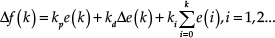
The GA is used for optimizing the parameters of the PID controller as an offline step. The general algorithm diagram of the PID control is expressed in Figure 12.
Control block for the PID control.
We have three parameters to be optimized for the system, (i.e., kp, ki and kd). The constraint criteria for the parameters are from 0 to 20. The fitness function is defined as follows:

where Vd is the desired speed, Vai is the actual speed of the robotic fish, and n is the number of the simulation results of the speed. The purpose of the fitness function is to reduce the oscillation amplitude, settling time, rising time and overshoot of the speed for the desired speed.
Since the GA is a stochastic method, which does not guarantee the achievement of an optimal result and is most likely return the results with different values for each run, it was decided to run the program expressed by Figure 12 several times in order to get some optimized parameters.
The simulation results of the algorithms in this paper are carried out using MATLAB with the toolbox of the GA [44]. The running time for the simulation was 100 seconds. The population size for the GA was set at 80, the generation was 150 and the crossover fraction was 0.6. The robotic fish was given two distinct desired speeds of 0.015 m/s and 0.02 m/s. The parameters for the PID controller were calculated using the GA.
5.2 Design of an efficient swimming controller
In the discussion of the optimal thrust efficiency in Section 4, we suggested that the efficient swimming of robotic fish does not depend solely on f, but that the amplitude of the input sinusoid voltage A should be actively controlled in association with changing f. The issue is: how do we apply this extensive knowledge and experience to the harmonic control of f and A so as to improve the thrust efficiency of the robotic fish? From our studies of the swimming performance of IPMC fish, we proposed a novel control method which could actively control the actuation frequency f and the voltage amplitude A.
5.2.1 The controller's fundamental structure
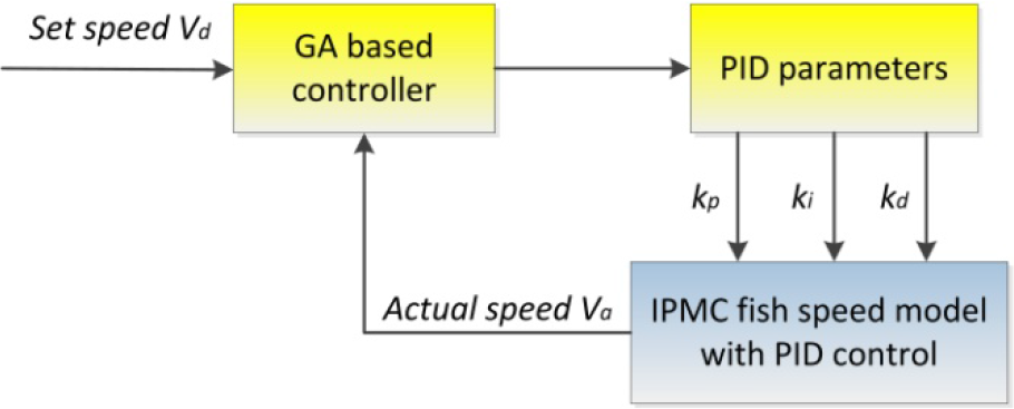
As can be seen from Figure 13, the basic structure of the control system consists of a fuzzy controller block, an expert controller block and a fish swimming dynamics block. The actual swimming speed Ua(t) is compared with the desired speed Ud to provide the speed error terms. The fuzzy controller determines the actuation frequency deviation f according to the speed error inputs, and the expert controller is applied to select the proper A associated with f. The fish swimming dynamics will result from the input parameters (i.e., f and A) and thus the robotic fish swimming speed is obtained.
Controller block for the robotic fish.
5.2.2 Design of the fuzzy controller
The fuzzy controller, which is shown by the dashed line box in Figure 13, can be viewed as an artificial decision-maker [45–46] that operates in the closed-loop speed control of the robotic fish. Here, a discrete-time controller with two inputs and a single output is considered for the implementation. The fuzzy logic controller is in association with the PD control. The inputs e(k) and Δe(k) have the same definition as expressed in Eq. (12). The actual range of values of e(k) is between −0.1 m/s and 0.1 m/s, and that of Δe(k) is between −0.2 m/s and 0.2 m/s. During the fuzzification stage, e(k) and Δe(k) are multiplied by scaling factors: k1 = 20, k2 = 5. The value of the input variable e(k) is then fuzzified and expressed as E, and denoted by the linguist fuzzy sets {NB, NS, ZE, PS, PB}, abbreviated from Negative big, Negative small, Zero, Positive small and Positive big. Δe(k) is expressed as EC and denoted by {N, ZE, P}, abbreviated from Negative, Zero and Positive.
The actual range of the controller output is −0.13 < Δf < 0.13. The output variable is expressed as Lst and denoted by the linguist fuzzy sets {NB, NS, ZE, PS, PB}, denoting Negative big, Negative small, Zero, Positive small and Positive big. The membership functions of the input (i.e., E and EC) and the output variable (Lst) are sets of overlapping values represented by Z and triangular and sigmoid shaped functions, as shown in Figure 14.
Figures 14(a) and (b) show the sets of membership functions for the speed error inputs, while the output f whose membership is shown in Figure 14(c) will be adjusted according to the inputs. It should be noted that the membership functions are determined by hydrodynamic knowledge and experience. As a simple example, when the membership function of e is within the domain [0, 2] for an actual value of 0 - 0.1 m/s, the current speed is lower than the desired speed. Meanwhile, for a domain of the output variable δf taking the range [0, 0.13], the actuation frequency of the robotic fish will increase in order to accelerate.

(a) Membership function of E; (b) Membership function of EC; (c) Membership function of output Δf.
The next step in the fuzzy controller is to specify the fuzzy rules that can be represented and stored by the fuzzy associative memory (FAM) matrix. A 2D (5×3) FAM matrix is given in Table 2, where the fuzzy rules are described using fuzzy linguistics, which consist of IF-THEN statements such as:
{If E is PB and EC is P, then Lst is PS}.
This fuzzy logic set can be interpreted as:
{When the difference between the desired speed and the current speed of the robotic fish E is positive and large, while the fish's forward acceleration EC is positive, then the robotic fish needs a small increment of f to accelerate to the desired speed Ud.}
In general, the IF-THEN statement is actually: {If E is Ei and EC is ECj, then Lst is Lstij}, where the subscripts i and j denote the ith and jth members of the fuzzy sets E and EC respectively.
Rule table for the fuzzy control.

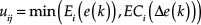
During the stage of defuzzification, we adopt the Mamdani fuzzy inference method, and the precise values of the output variables are determined using the centre-of-gravity (COG) defuzzification method:

where uij is the weight factor, which is obtained by Mamdani inference with minimum for intersection and maximum for union. At a certain instant k, the weight factor can be expressed by the following:
In addition, and as seen from Figure 13, the output value of Δf will be multiplied by the scaling factors: k3 = 15. Consequently, at a certain instant k, the frequency can be obtained:

The efficient propulsion of the robotic fish can only be achieved by adopting a harmonic combination of f and A, as indicated previously. The purpose of the expert controller is to choose the appropriate maximum voltage amplitude for different actuation frequencies at certain instants. Piecewise, in terms of the distribution function, the expert controller is given by the following:

Substituting the frequency f and voltage amplitude A into Eq. (4), we can solve the swimming speed Ua of the robotic fish. The whole control process was implemented in MATLAB.
5.2.3 Simulation results
The simulation results of both the speed response and thrust efficiency using the PID and fuzzy controllers are evaluated and compared in this section. The parameters of the IPMC sample obtained in Section 4 are adopted for both the methods, and the parameters for the PID controller are: kp = 3.7, ki = 5.2×10⁻⁵ and kd = 1.1×10⁻³ for Vd = 0.02m/s and kp = 2.6, ki = 5.2×10⁻⁵ and kd = 6.8×10⁻⁶ for Vd = 0.015m/s, which were optimized by the GA. The actuation frequency can be controlled via Eq. (11) and Eq. (15). The amplitude of voltage is fixed at 3.3 V for the PID controllers.
1) Swimming speed
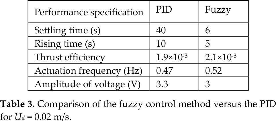
Figure 15(a) shows the velocity of the robotic fish in the forward direction over 60 s of body movement. The robot is given two distinct desired speeds (Ud) of 0.015 m/s and 0.02 m/s. We assume that the step is one second, which means that it takes the fish one second to reach the steady cruising state under the frequency f(k). During the initial start phase, the speed under fuzzy control and PID is seen to accelerate equally (see Figure 15(a) for details). The settling time at the input speed of 0.02 m/s is 40 s for the PID controller and 6 s for the fuzzy controller, while the rise time is 10 s for the PID controller and 5 s for the fuzzy controller. Almost no overshoot and oscillation was observed for either the PID or the fuzzy controller. The fuzzy method shows better tracking performance than the PID. The PID's swimming performance lags far behind the performance of the fuzzy method, as can be seen from Table 3, which provides the qualitative results of the speed response. It should be noted that both of the close-loop methods have small tracking error values and a best convergence on zero.

(a) Simulation speed for the desired speed Ud of 0.015 m/s (drawn curve) and 0.02 m/s (dashed curve); (b) Simulation of the actuation frequency f for Ud = 0.02 m/s.
2) Thrust efficiency
Taking into account the thrust efficiency reported in Table 3, the most important findings are: 1) An IPMC fish with fuzzy control swims more efficiently than with the PID controllers; 2) In a steady swimming state, a smaller voltage amplitude is needed using the fuzzy controller when compared with PID methods. As can be seen from Figure 15(b), for the initial 2 s, both the PID and fuzzy control methods employed a relatively high growth of frequency. After several laps, which take about 10 s, the frequency for these two methods becomes unequal. The frequency for the fuzzy controller appears to gradually increase and reach a constant value (where A = 3 V). However, when it comes to the PID controller, a slower rise is observed. Then it gradually reaches a low constant value (where A = 3.3 V). This behaviour is the result of the proper control of the IPMC vibration using the fuzzy control method.
From Table 3, it can be observed that the robotic fish with fuzzy control has a higher efficiency η with a higher actuation frequency f and a lower voltage amplitude A than the PID method. With the definition of the thrust efficiency η expressed in Eq. (7) and the simulation results in Figure 11, it is not difficult to establish why a higher η can be obtained using the present method. According to Figure 15(b), we see that f via the present fuzzy method is controlled within a certain range, which would not exceed its optimal point of speed. Therefore, we can speculate that this method could find its relative high frequency for the desired speed so as to achieve better thrust efficiency. The fuzzy control method presented here shows the feasibility for speed tracking as well as maintaining relatively high thrust efficiency for robotic fish.
Comparison of the fuzzy control method versus the PID for Ud = 0.02 m/s.
6. Conclusions and future work
This paper has proposed a dynamic model of an IPMC-actuated robotic fish that incorporates both the hydrodynamics of an IPMC fin and the actuation of the IPMC itself. The simulation speed and thrust efficiency results are validated by comparison with experimental results. The results demonstrated that the optimal actuation frequency for the thrust efficiency showed relatively good agreement with that for the self-propelled speed. Based on the present dynamic model, the harmonic control of the actuation frequency and voltage amplitude of the IPMC proved to be a principal mechanism through which the robotic fish achieved high thrust efficiency. This is also the most important reason why the fuzzy control method - which was successfully applied to this principal mechanism - offered better swimming performance and higher thrust efficiency than the conventional PID controller. However, in this paper we carried out the exploration of the modelling and fuzzy control of an efficient-swimming IPMC fish and the current work does not include the experimental investigation of the developed fuzzy controller due to the difficulty of obtaining the fish velocity feedback. In the near future, an online control system with vision-based velocity measurement apparatus will be developed and the real robotic fish with the fuzzy controller will be tested in experiments. We will also use multiple layers of IPMCs as actuators to study the thrust performance. Other available control techniques such as gain scheduling and adaptive control techniques will be used and compared with the results of the fuzzy control approach.
IPMCs are one kind of promising material for the development micro-underwater robots. However, due to the limitations of their manufacturing techniques, few studies have been reported of IPMC-actuated underwater vehicle of a very small size (< 1 mm). In our future work, we will study the IPMC fish's thrust performance in viscous and inertial flow. In addition, there might be external perturbations on the practical application of IPMC fish, such as vortices and waves. Therefore, new control systems will be investigated for the stability of robotic fish in disturbed flow.
Footnotes
20. Acknowledgments
Many thanks to Yang Chen and Lei Bao for their contributions to this paper. This work was supported by the National Natural Science Foundation of China (Grant No. 61075100). The authors would like to thank the referees for their careful reading of the manuscript and their helpful comments.