
Abstract
In this work, we address the problem of global attitude control using direct inertial measurements. When using direct inertial measurement to observe the rigid body attitude, it is shown that due to a geometrical obstruction, it is impossible to achieve global asymptotic stability. In fact, for a particular initial condition the tracking error quaternion converges to a pure imaginary quaternion formed by an eigenvector of a characteristic matrix related to the inertial constant and known vectors. Our proposition consists of adding a dynamic signal to force the rigid body to escape from such a situation. The proposed observer-based controller is synthesized based on a single Lyapunov function and a stability analysis shows that the controller stabilizes globally and asymptotically the rigid body attitude at the desired one. The effectiveness of the proposed observer-based controller is confirmed by simulation results.
Introduction
Rigid body attitude belongs to the special orthogonal group SO(3), formed of 3 × 3 rotation matrices defined by nine elements and subject to six constraints [1]. There are other minimal parametrizations of the attitude representation including unit quaternions parametrization. The latter is the only reduced four parameter parametrization that is globally defined for all attitudes and subject to only one constraint (the unit quaternion length constraint). Mathematical operations on unit quaternions are simpler and more computationally efficient than on the SO(3) group. For these reasons, unit quaternions are very useful in attitude control synthesis as well as in computer 3D animations.
Rigid body attitude control is one of the canonical non-linear control problems [2] and “global attitude stabilizing” is a difficult problem which is still challenging. It was formally shown in [3] that the topology of the attitude space precludes the existence of continuous time invariant control that achieves global asymptotic stability of the closed loop. In addition, this result is directly applicable to mechanical systems having rotational degrees of freedom, as is the case for rigid body attitude control.
Traditionally, in synthesizing a quaternion-based feedback controller, it is common usage to make stable and attractive one of two antipodal quaternion equilibria (since they represent the same attitude) and let the other be unstable and repulsive as in [4]. In this case, the controller is not well defined on SO(3) × ℝ3 and it is then said to be inconsistent (see [5] and [6]) and can exhibit the unwinding phenomenon. Therefore, the best that can be achieved by this kind of attitude controller is solely almost global asymptotic stability [5]. However, synthesis of a global set stabilizing controller is possible (see for example [7–9]). Indeed, in the recent literature, many works have treated this problem in different ways. For example, in [7] a global set stabilizing scheme using a finite-time technique was proposed with the addition of a power integrator method - this was used to prove the global set stability of the closed loop. While in [10], the same authors addressed the same problem by using optimal control to design a virtual optimal angular velocity for the kinematic equation and finite-time control techniques for the dynamic subsystem. It was then proved that the closed loop system satisfies global set stability in the absence of disturbances. While in the presence of disturbances trajectory will converge to a neighbourhood of the equilibrium set. Note that in both preceding works, the resulting control is discontinuous in the initial state.
Practically all proposed attitude controllers, in the related literature, are state feedback controllers relaying on the availability of system states, such as attitude and angular velocity. It is worth noticing that there are no sensors that give the attitude information directly. To overcome this limitation in attitude sensing, several sensors are often made use of such as 3D-gyroscopes, 3D-gyrometers and 3D-magnetometers, which are generally grouped in a single device known as an Inertial Measurement Unit (IMU). The attitude is then extracted by using filtering techniques and data fusion. The 3D-gyroscope output is directly related to the rigid body angular rates about its principal axes. While the 3D-accelerometer measures the body total translational accelerations sensed along its three principal axes. The total body translational accelerations are the sum of the body translational movement and the apparent translational accelerations due to the effect of the gravitational acceleration projected on the body principal axes, which are directly related to the body attitude. The 3D-magnetometer measures the projection of the Earth's magnetic field on the body principal axes. As with the apparent translational accelerations, the 3D-magnetometer output is directly related to the body attitude.
For aerospace applications, there is a variety of reliable and precise sensors that give the needed attitude information. These sensors are expensive, heavy and power consuming. Nowadays, there is a special class of small aerodynamic systems such as mini Unmanned Aerial Vehicles (UAVs), that are constrained in weight, energy and budget, and for which these sensors are not affordable. Fortunately, there are very compact and less expensive sensors, based on Micro-Electro-Mechanical (MEMs) technologies, that are compatible with this special class of systems. But, MEMs sensors are less precise and still pose problems such as sensitivity to noise and time-dependent drift.
Recently, some works in the attitude control literature have used the direct inertial measurement vectors to solve the attitude control problem. For example in [10], the authors addressed the question of obtaining high quality attitude estimates from typical low cost inertial measurement units for applications in the control of unmanned aerial vehicles. They proposed a nonlinear complementary filter, expressed explicitly in terms of direct and untreated measurements (Earth's gravity and Earth's magnetic field) by exploiting the structure of Special Orthogonal Group SO(3). They have also shown that using only the gravity inertial measurement along with gyro measurements allows correct estimation of the full gyro bias vector and that the estimated orientation converges to a set consistent with the measurements. In [11], the authors used a single inertial measurement vector (i.e., Earth's magnetic field vector) to synthesize a coupled nonlinear estimator-controller for satellite attitude control. We note that the authors have considered an unknown inertia matrix. In [12], the authors used vector attitude measurements to estimate the attitude quaternion and proposed a new adaptive control scheme to deal with unknown inertia matrix and gyro-bias parameters. Based on inertial measurements, the authors in [13] have proposed in the first step an attitude estimator and in the second step a velocity-free attitude stabilization scheme. In [14], authors have proposed a globally convergent quaternion-based discontinuous attitude observer using inertial measurement vectors. In [15], the authors proposed a velocity-free attitude stabilization control scheme relying solely on inertial vector measurements, where only almost global asymptotic stability is guaranteed.
In the present work, we address the problem of attitude control on the unit quaternion space ℚ u , using directly the on-board inertial measurement vectors. The observer correction error consists of a collinearity measurement between the estimated and true inertial projection vectors, on the rigid body frame. Since the collinearity measurement between two orthogonal frames (i.e. the observer frame and the rigid-body frame) does not tell us what are the axes parallel to each other and whether they are or are not in the same direction, it is possible to have a zero observer correction error, while both frames are not properly superimposed. In such a situation, the scalar part of the error quaternion is zero. Starting from such a condition, the controller will be inhibited and will give a null command since the control objective seems to be achieved. To eliminate this situation, we have proposed augmenting the observer correction term by a time-varying signal with a special initial nonzero condition, allowing the observer to move in the direction of the correct collinearity, between the two frames. The synthesis technique we adopt in this work is the Lyapunov method consisting of choosing an appropriate energy-like function constructed from the system's closed-loop errors and synthesizing the control law negating the time derivative of that energy.
The rest of this paper is organized as follows. Section 2 gives some necessary mathematical background on the system dynamics and unit quaternion. Section 3 is devoted to the observer-based controller synthesis where the result is given in terms of a theorem with its proof where the stability analysis is given. Section 4 presents some relevant simulation results and finally Section 5 presents a conclusion on the obtained results.
Mathematical Background
Attitude kinematics and dynamics, and problem formulation
The attitude of a rigid body is represented by a 3 × 3 orthogonal matrix with unitary determinant: an element of the special orthogonal group of order three,

where ℝ represents the set of real numbers.
The rotation matrix R transforms vectors expressed in the inertial frame
The simplified rigid body dynamics (without the gyroscopic effect) is described on SO(3) by the kinematic equation

and the dynamic equation

where ω ∊ ℝ3 denotes the rigid body angular rate, J = J T ∊ ℝ3×3 represents the symmetric positive definite inertia matrix of the rigid body matrix with respect to its principal axes and τ ∊ ℝ3 represents the vector of external torques. While S(u) is a skew symmetric matrix associated to a vector u = [u1, u2, u3] T and given by:

The cross product between two vectors,

Usually in quaternion-based controller synthesis one stabilizes one quaternion equilibrium point and makes the other unstable. However, this type of controller is only efficient for closed sub-regions of the attitude space SO(3), while in the rest of the attitude space it exhibits the unwinding phenomenon (see, for instance, [1] and [3]).
For the same attitude there are two conjugate quaternions thus in ℚ u there are two ways to reach the same attitude on SO(3) with two different controls depending on which quaternion equilibrium we choose. Among these two ways there is always a short one.
Our objective is to design a quaternion-based controller that globally and efficiently (without unwinding) stabilizes the rigid body attitude at any desired attitude on SO(3) space.
In the following, we reproduce the definitions and mathematics of [16], with a different notation. A quaternion
The set of quaternions ℚ is a four-dimensional vector space over the reals, which forms a group with the quaternion multiplication denoted by *. The quaternion multiplication is distributive and associative but not commutative. The multiplication of two quaternions q1 = (η1, ε1) ∊ ℚ and q2 = (η2, ε2) ∊ ℚ is given by

The quaternion multiplication operation has the quaternion (1,0) as the identity element. Note that, for a given quaternion q = (η, ε), we have q * q−1 = q−1 * q = (1, 0), where

Note that in the case where q = (η, ε) ∊ ℚ
u
, the unit quaternion inverse is given by q−1 = (η, −ε). A rotation matrix R ∊ SO(3) by an angle γ about the axis described by the unit vector

Algorithms that allow us to obtain the matrix R from the unit quaternion q as well as the extraction of q from R, can be found in [17]. In this paper, instead of using the rotation matrix R to describe the orientation of the rigid body in space, we will use the unit quaternion. In terms of unit quaternions, the kinematic equation (2) is equivalent to:

where, q = (η, ε) ∊ ℚ u and v (ω) = (0, ω) ∊ ℚ.
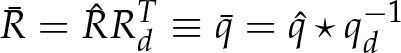
For two unit quaternions q1 and q2 corresponding to rotation matrices R1 and R2 respectively, the attitude error matrix

Note that the unit quaternions q1 and q2 coincide if
Given the rigid body dynamics (3) and (9), the main objective is to make the rigid body attitude track the desired bounded and smooth attitude given in terms of a desired quaternion qd and a desired angular velocity ω d with the following dynamics:

It is assumed that the real rigid body attitude is not known. The only information about it is the n projections

Since, the real attitude is unknown, we propose the following attitude observer:
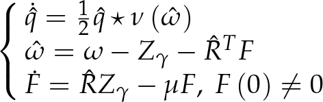
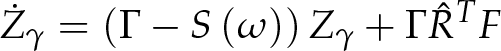
where μ ∊ ℝ+ is a design parameter and Z γ represents the attitude estimation error given by [15]:
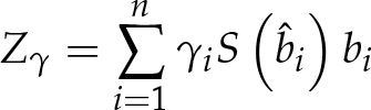
with γ i ∊ ℝ+ representing weighting factors.
In (14), the vectors

Physically, Z
γ
is the measure of collinearity between the estimated and the measured inertial vectors. Of course, when the measured and the estimated vectors are collinear, the resulting collinearity measure Z
γ
is null. Note that Z
γ
= 0 does not tell us whether or not the collinear vectors are of the same length or whether or not they are in the same direction. This remark will be useful in the following stability analysis. In general, for endoatmospheric aerodynamic systems like UAVs in near-hover conditions, the considered inertial vectors are the gravitational vector
Before stating our main result, we define the following useful errors and their dynamics. First, we define the true tracking error

whose dynamics are given by

Secondly, we define the estimated tracking error
whose dynamics are given by

Finally, we define the estimation error R e ∊ SO(3) or q e ∊ ℚ u between the true rigid body attitude and its estimate, as

whose dynamics are given by

Mathematically, the objective is to drive the estimated tracking error quaternion
From the definition of Z γ and q e , it is shown in [15] that

where W γ ∊ ℝ3×3 is a constant symmetric and positive definite matrix, given by:

Now, we are ready to state our main result.

with
Proof. Consider the candidate Lyapunov function:

with
The sign function is defined by:

Note that similarly to the work in [7–9], we have introduced a discontinuity in the initial state sign(
Differentiating (25) with respect to time, yields

Computation shows that:
with

We can see that

For the autonomous dynamics (30), we can use LaSalle's invariant set theorem to establish its stability. From the Lyapunov candidate function (25) and its time derivative (29), it is clear that

From (30), we have
A desired equilibrium set S
D
= qe = (±1,0); And an undesired equilibrium set S
U
= q
e
= (0, ±v
i
).
Note that, geometrically, the undesired equilibrium set corresponds to a solution:

Thus, we can have a positive collinearity test between two sets of vectors (i.e., two frames) over a true superimposition, and this represents a geometric limitation of the collinearity test. From (30) and (22), we have the following dynamics:

At the desired equilibrium set, (32) yields:
which means that the desired equilibrium set is attractive and stable. While at the undesired equilibrium set, it yields:

From (35), we note that

By examining the dynamics of F at Z
γ
= 0, the vector signal F will approach zero exponentially, which means that
Since the conditions (36) should also hold for t = 0, we can simply choose as initial condition F(0) a linear combination of the eigenvectors vi as follows:

where σ i ≠ 0 are three arbitrary real constants.
Finally, the largest invariant set resumes to the desired equilibrium set defined by:

By LaSalle's invariant set theorem, we conclude that the desired equilibrium set Se is globally asymptotically stable. Then, it follows that:
Using the error definitions (16), (18) and (20), we can write:
Then from the above results, we have
Which terminates the proof.
In order to verify the theoretical results given above, we performed computer-based simulations on an experimental model of a quadrotor UAV, detailed in [18]. The quadrotor UAV is a rotor-wing type aircraft capable of vertical take-off and landing (VTOL). Mechanically, it consists of a rigid cross frame equipped with four rotors as shown in Figure 1. Two diametrically opposite rotors rotate clockwise while the other two rotate counter-clockwise, in order to eliminate the gyroscopic effect due to rotor rotations. By properly controlling the rotation speed of each rotor, the quadrotor can achieve six degrees of freedom. Thus by its construction, the quadrotor is an under-actuated system where the translational movement is coupled to the rotational movement.

Quadrotor aircraft
Since, in the mathematical model (3) and (9), the torques are considered as control inputs and the gyroscopic effect is not considered, only the quadrotor inertia matrix is necessary. This inertia matrix is symmetric and diagonal given by J = 10−3diag(7.5, 7.5, 13).
The controller parameters are chosen as α = 100, β = 14 and the observer gains are taken equal γ1 = γ2 = 15 and μ = 10. The inertial vectors are given in a normalized form as:
Normalized gravitational vector: r1 = [0,0,1]
T
; Normalized Earth magnetic field:
According to the above parameters, the eigenvectors of W γ and their respective eigenvalues are given in Table 1.
Eigenvectors and eigenvalues of W γ
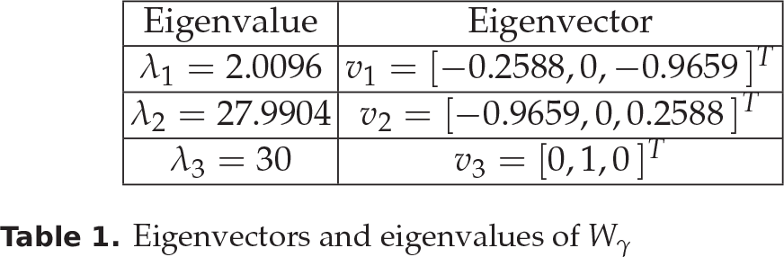
For all simulations below, the initial condition for the signal F is simply taken as: F(0) = v1 + v2 + v3.
In the following simulations, four cases are considered. In the first three cases, we considered attitude stabilization at the desired attitude qd = (0.6,0, −0.8,0) for three different conditions such that η e < 0, η e = 0 and η e > 0, in order to show the global convergence property of the proposed controller. In the fourth case, we considered the attitude trajectory tracking in the presence of measurement noise and a disturbance, in order to illustrate the behaviour of the UAV and the effectiveness of the proposed controller in more realistic flying conditions.
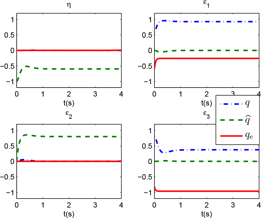
In this first case, the initial conditions are q(0) = (1,0) and
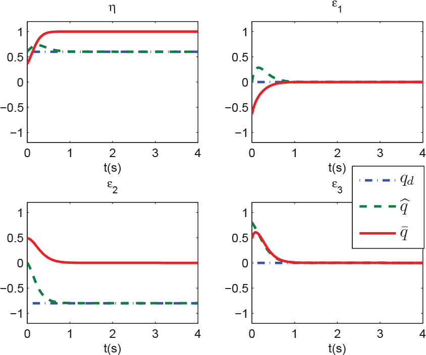
Case 1: Estimated quaternion versus desired quaternion

Case 1: Real quaternion versus desired quaternion

Case 1: Real, estimated and estimation error quaternions

Case 1: True b, desired b
d
and estimated
In the second case, we have chosen the initial condition as q(0) = (0,0.6,0,0.8) and

Case 2: Estimated quaternion versus desired quaternion

Case 2: Real quaternion versus desired quaternion

Case 2: Real quaternion versus estimated quaternion

Case 2: Real and estimated inertial vectors versus desired ones
Case 2: Real versus estimated quaternions, when F = 0

Case 2: Real and estimated inertial vectors versus desired ones, when F = 0
In this third case, the initial conditions are q(0) = (1, 0) and

Case 3: Estimated quaternion versus desired quaternion

Case 3: Real quaternion versus desired quaternion

Case 3: Real, estimated and estimation error quaternions

Case 3: Real and estimated inertial vectors versus desired ones
In this last case, we considered a trajectory tracking. The initial conditions are q(0) = (−0.8, 0, 0, −0.6) and

Case 4: Angular velocity disturbance

Case 4: Real quaternion versus desired quaternion

Case 4: Real versus desired angular velocities

Case 4: Real and estimated inertial vectors versus desired ones

Case 4: Additive signal F

Case 4: Control torques
In the present work we proposed an observer-based controller for rigid body attitude stabilization and tracking, using direct inertial measurements. The controller was synthesized on the unit quaternion space ℚ u where the problem of unwinding phenomenon apparition is considered. We showed that the frames' misalignment characterized by the collinearity measure is not sufficient to achieve global asymptotic stability of the observation error, due to the existence of a non-attractive undesired and stable manifold corresponding to η e = 0. In fact, when the rigid body is in such a situation, the main observer error, namely Z γ , is null, while the observed attitude quaternion and the real one are not equal. The reason for this is shown to be a geometric obstruction that gives other solutions to the alignment of estimated and true measured inertial vectors. In fact, geometrically, the sum of misalignment between a set of vectors and their rotational projection can be found to be zero, even if each individual vector is miss-aligned with its own projection. In this case, the vectors interchange their projections. So, in the case where we have no information on the initial rigid body attitude, we are not able to choose the observer initial state in order to prevent this phenomenon. We solved this problem by adding a suitable dynamics consisting of a time-varying signal that destabilizes the undesired manifold η e = 0. Provided some constraints on the additive signal initial condition, we managed to achieve global asymptotic stability for both the observer and the controller. In the recent literature, the problem of global attitude stabilization using inertial measurements is widely treated and different solutions are proposed. To the best of our knowledge the proposed solution is new and original.
The simulation results given here show the efficiency of the proposed observer-based controller for attitude stabilizing as well as for tracking time-varying attitude trajectories in the presence of noisy measurements and a disturbance. Through the different simulation cases, the global convergence property of different error quaternions is well illustrated. Although no robustness to noise analysis was performed, the simulations show the effectiveness of this control law when angular velocity is corrupted by a centred Gaussian noise. In addition, in the second simulation case, the role of the additive signal F is clearly illustrated by the comparative simulation results performed without the additive signal F.