
Abstract
This paper deals with the landing motion of an articulated legged robot. Humans use a peculiar crouching motion to land safely which can be characterized by body stiffness and damping. A stiffness controller formulation is used to realize this human behavior for the robot. Using this method, the landing motion is achieved with only the desired body stiffness and damping values, without desired COG(Center of Gravity) or joint paths. To achieve soft landing, variable body stiffness and damping values were optimized.
PBOT, which has four links with flexible joints was used for validation of the landing controller. A body stiffness and damping controller was used as an outer landing control loop and a fast subsystem controller for flexible joints was used as an inner force control loop. Simulations and experimental results about the landing motion are presented to show the performance of the body stiffness and damping controller.
Introduction
In human motion analysis, a hopping motion is usually modeled as a simple spring-mass(Blickhan, R. (1989), Farley, C. T. & Gonzalez, O. (1996)). This model is realized in robotics through various experiments by compensating energy loss using bounce of leg by Raibert(Raibert, M. H. (1985)). After this, similar investigations were published(Gregorio, P.; Ahmadi, M. & Buehler, M. (1994), Berkermeier, M. D. & Desai, K. V. (1999)). Most of them used the identical mechanical structure with some advanced features in hopping method and in structure.
Running and hopping of the biped humanoid robot is now a very challenging area to make humanoid more agile and fast motion. There were some research efforts(Chevallereau, C.; Westervelt, E. R., & Grizzle, J. W. (2005), Park, J. H. & Kwon, O. (2003)) to make an articulated legged robot running by various path planning and nonlinear control techniques. In 2003, Sony realized running motion using biped humanoid robot QRIO(Nagasaka, K. et. al.; Kuroki, Y.; Suzuki, S.; Itoh, Y. & Yamaguchi, J. (2004)). In 2004, Honda demonstrated running in human size biped robot using ASIMO(Honda) and enhanced speed up to 6km/h. In (Nagasaka, K.; Kuroki, Y.; Suzuki, S.; Itoh, Y. & Yamaguchi, J. (2004)), method for acquiring analytical solution of the x-, y- COG path considering angular momentum using dynamic boundary conditions is presented for the running motion. In (Kajita, S.; Nagasaki, T.; Kaneko, K, Yokoi, K & Tanie, K. (2004)), the desired angular and linear momentum is calculated from a predetermined COG and the robot is controlled through the developed controller.
However, a limitation of these previous researches about humanoid was that controller follows desired COG path or dynamic boundary condition provided by the operator. This can produce unexpected foot touch-downs so that the COG path must be corrected to ensure motion stability because of the difficulty in predicting impact timing and robot state after impact. In the case of running and landing motion of humans, the characteristic named body stiffness and damping is used(Poul, E. B.; Poulsen, D. & Voigt, M. (1991)) to hop or land. It is known that a human behaves like a spring at the beginning of the impact and changes behavior into damping characteristics.
In this paper, a body stiffness and damping controller which resembles human's landing strategy will be applied to landing motion of legged robot, PBOT (Fig. 1) which has been made for hopping or running motion. The articulated legged robot system is assumed as a lumped single mass (COG) and forces from body stiffness and damping is applied on COG as a virtual force. Similar approach using body compliance was tried by (Ohashi, E. & Ohnishi, K. (2004)). But this method also follows desired path while requiring force and acceleration sensor signals to follow desired body impedance. The method developed in this paper utilizes simple structure of stiffness controller which needs only position and velocity signals with desired body stiffness and damping values.

Photo of PBOT
Target control motion is drop landing which starts motion from given height with standstill to the ground until robot stops motion. Constant and variable body stiffness and damping value case will be introduced and compared to each other. Variable value case shows soft landing behavior which resembles human behavior. Section. 2 describes PBOT specification. In section.3, we validate body stiffness and damping strategy using two mass system simulations. Section.4 introduces application processes of body stiffness and damping controller to the articulated legged model and fast subsystem controller. Section.5 shows experimental result of body stiffness and damping control with PBOT.
PBOT (Fig. 1) is a four-link (foot, shank, thigh, torso) legged robot that has 3 actuators and 9 degrees of freedom (x; y; μ0; μ1; μ2; μ3; Z1; Z2; Z3) for the planar motion, where Zi is a flexible force coordinate (spring force) for ankle, knee and hip joint(belt force from belt deflection). Linear actuation structure is used for ankle and knee joint which uses series elastic actuator(Pratt, G. A. & Willianson, M. M. (1995)) where ball screw and spring (60kN/m) are serially connected with motor to allow shock tolerance about impact situation. Linear actuator is connected to the robot by forming closed kinematic chain with flexible joint around ankle and knee joint. Hip joint is actuated by a rotary motor with gear through belt transmission. The foot of PBOT is a planar foot which has four FSR (Force Sensing Resistor, used for touch sensing) at its corners. Beneath the foot there is rubber for shock absorption with 2.5mm thickness.
Encoders of 6 are installed to measure joint angles and linear displacement of the springs. Absolute angle of the foot is measured using INS (gyro) sensor. PBOT weighs 7.9kg and stands 0.95m tall. A dimension is based on small adult and detailed dimensions are in Table. 1.
Kinematic and mass data for PBOT

Kinematic and mass data for PBOT
To make a landing strategy for a robot, it is important to understand human's landing strategy. Human's landing strategy has a relation with shock absorption for ground impact which can be divided into two categories. One is shock absorption by materials using muscles, tendons and foot heel pad. The other is shock absorption by motion like crouching which can be seen at the gymnastic competitions. Impact force is transformed into another energy form like potential energy (stored at the elastic material) or kinetic energy. In this paper, we use this human's motion behavior for shock absorption to make robot land on the ground.
To apply human's behavior to the robot, we need mathematical description of human's landing motion. From biomechanics study, a human's hopping and landing behavior was explained using parametric study. When the human hops continually, leg stiffness value increases from touch-down to take-off with the same initial value on every instants(Poul, E. B.; Poulsen, D. & Voigt, M. (1991)). When landing, the human also behaves like mass with spring-damper system. Initially, human acts like spring on landing but changes action into damping. Leg stiffness is expressed as

where Fpeak is peak reaction force in the force platform when human jumps onto platform and ¢ L is a vertical displacement of body's center of mass.
Using this human's vertical spring and damper-like motion behavior, we apply similar strategy to legged robot landing control. Leg stiffness kleg is changed by body stiffness kleg which is expanded from leg motion to whole body motion and force platform force Fpeak by Fg Which is a force on center of gravity transferred from the ground.
In this section, one dimensional (vertical directional) model (Fig. 3) composed of two masses is used to see the effect of body stiffness and damping action on landing motion. Upper mass (7.15kg) represents lumped mass of the whole body (legged robot, humans, etc.) and lower mass (0.75kg) is used to describe impact phenomenon with the ground.

PBOT model description

1-D two mass system
To apply body stiffness, (X1 - X2) at impact time is used as a definition of equilibrium length for stiffness. Thrust force from body stiffness and damping is expressed as,

Fig.4(a) shows the result of drop landing simulation with constant values of K (2000N/m, stiffness of the system) and D (200Ns/m, damping of the system) at 0.1m initial height (X2). We can see that the two-mass system has landed on the ground showing body stiffness and damping behavior on X1. Landing was possible because spring element stored energy with upper mass support while damping element dissipated kinetic energy. Fig. 4(b) shows upper mass motions after landing which can is controlled through changing the stiffness and damping values.

1-D body stiffness and damping results
From human's case, it is known that body stiffness and damping behavior is changed from spring to damper which is not constant. If we see Fig. 5(b), we can see impulse thrust force from constant body stiffness and damping value case which is unrealistic thrust force in real experiment. Also thrust force is transmitting impulse force to the upper body. To make body stiffness and damping controller more feasible for landing motion, variable value case like human's behavior is needed.

Constant and variable K & D results comparison
In (Rapoport, S.; Mizarahi, J.; Kimmel, E.; Verbitsky, O. & Isakov, E. (2003)), the joint stiffness was found to be first-order in human hopping motion. And from Farley, C. T. & Morgenroth, D. C. (1999), we can assume body stiffness as first-order using the result of (Rapoport, S.; Mizarahi, J.; Kimmel, E.; Verbitsky, O. & Isakov, E. (2003))]. To define variable body stiffness and damping profiles, we assume the model of body stiffness and damping value as a first-order model as follows.


where t is a time after impact timing.
Fig. 5(a) shows comparison of upper mass position between constant and variable body stiffness and damping value cases. The motions of each case are similar in its fashion but required thrust force (Fig. 5(b)) is different from each other. Variable body stiffness and damping value case shows moderate increase of thrust force whereas constant value case shows impulsive force peak. At variable value case, zero initial body damping is used to prevent impulsive force transmission to upper body, while nonzero body stiffness is used to prevent excessive undershoot of upper mass at initial contact duration.
From the two mass drop landing simulation, it is identified that human's body stiffness and damping behavior can be used as a landing motion controller about the system described like Fig. 3.
In this section, this humans's motion characteristic, i.e. body stiffness and damping behavior is applied to the landing strategy for the articulated legged robot system. First, definitions of body stiffness and damping on articulated legged model will be explained. And then, development processes from desired body stiffness and damping values to the controller formulation for flexible joint of PBOT are explained. Block diagrams in Fig. 6 helps understanding of the processes.

Control block diagram
Though there are actual springs in the actuator (at series elastic actuator), the stiffness of the spring is a fixed value. To assign arbitrary stiffness and damping value to the robot, a stiffness controller formulation is used here. The stiffness controller is a force controller to react against external force, but we use this controller to react against vertical COG motion (
where 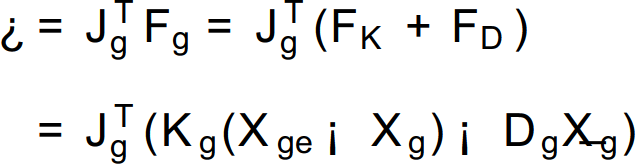
The COG Jacobian is calculated only when the foot is contact with the ground. If we determine Jg at global frame (coordinate attached at the ground at Fig. 2), Jg is changed according to contact mode (heel point contact, toe point contact and full line contact in 2-D case). On point contact case, contact point becomes under-actuated joint (passive joint) while nonzero desired torque is assigned by COG Jacobian (Eq. (6)) on that joint.
In this paper, to avoid from above mentioned case, we use a local frame which is attached at the foot (Fig. 2) as a reference coordinate for COG Jacobian. Desired COG force in global frame is projected into the local frame (Eq. (7)) to thrust robot into right direction. Flexible force coordinate (Z1, Z2, Z3) is ignored in calculating COG Jacobian.

where
It is assumed that μ0 is small enough and foot contact (point, line) is ensured through suppression role of the controller about contact point (it is known that suppression controller is good at decreasing pre-transition phase (Doh, N.; Chung, W. K.; & Youm, Y. (2000)), and the body stiffness and damping controller continuously suppresses contact point by thrusting force). In experiment, μ0 is acquired through INS sensor which has 70Hz frequency enough for control. Drift problem of INS can be neglected because of short running time of landing experiment.
There are 3 actuator degrees of freedom (ankle, knee and hip) whereas the motion degrees of freedom is 2(
Desired joint torques obtained from above section are transformed into desired actuator force on each actuator module using the derivation process of dynamics by closed chain kinematics characteristics(Ghorbel, F. H.; Chetelat, O.; Gunawardana, R. & Longchamp, R. (2000)) of model. To follow desired actuator forces in flexible joint system, force tracking controller is developed. All the joints of the PBOT are flexible joints which have transmission through springs and belt. To develop force tracking controller, we change dynamics in singularly perturbed form(Readman, M. C. (1994)) as,

where
Above dynamics equation can be divided into slow and fast subsystem. Slow subsystem (upper part of Eq. (8)) represents motion of the slow variables like rigid links and fast subsystem (lower part of Eq. (8)) represents motion of the spring and belt. Solving Eq. (8) for  gives Solving Eq. (8) for
  gives
gives
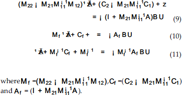
If we select control input

Eq. (11) changes into

To make the closed loop fast subsystem (Eq. (13)) asymptotically stable, all of the coeffcient matrix at the left-hand side must be and positive definite(Leang S. S.; Mohamad, M. M. & Hani, M. D. (1987)). Since
Drop Landing Simulation of PBOT
Developed body stiffness and damping controller will be used for drop landing simulation from given height. Simulation model is based on the parameters at Table. 2.
Landing simulation with 5˜10cm drop

Landing simulation with 5˜10cm drop
To validate developed body stiffness and damping controller, constant body stiffness and damping value case is first tried.

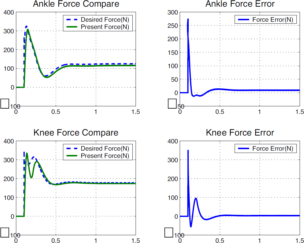
Desired & present actuator force and error for 5cm drop case
Large force tracking error at knee actuator right after the impact time is because ankle joint torque is highly coupled with knee joint torque, which can be identified from

Desired & present actuator force and error for 10cm drop case

Landing simulation of PBOT
Though we were not aware of the exact impact time, articulated legged robot was able to land with soft upper body motion by assigned body stiffness and damping values. If initial height is 10cm,

Desired & present actuator force and
Before applying variable body stiffness and damping value, it is important to know which values of coeffcients (Eq. 4) are suitable for landing motion. In case of constant value case, we can follow the processes in (Balandin, D. V.; Bolotnik, N. N. & Pilkey, W. D. (2001)). To determine the coefficients of body stiffness and damping value for variable case, multiobjective optimization with simple model (Fig. 3) is used to get cofficients according to given conditions. An Objective function for optimization can be decided as a thrust force peak minimization (because of actuator limit). Optimization constraints can be selected like these.
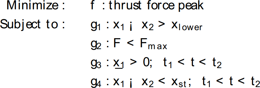
where Fmax is
Initial positions for drop landing are
The optimization result is in Fig. 12(a) for initial body stiffness value with 2000N/m. Both of the stiffness and damping values have been increased for landing motion. If initial stiffness value is large, stiffness value is decreased to diminish thrust force peak. On the contrary, small initial stiffness value causes increasing slope of body stiffness to prevent excessive undershoot (

Variable body stiffness and damping case
If we see force tracking result (Fig. 13), we can see that desired actuator force has been changed into moderate increase comparing with constant values case. In case of ankle, force tracking error decreased into small amount of value. But in knee joint, though desired actuator force has been changed into moderate increase, spring flexed abruptly because of impact force which is inevitable. Although optimized value does not guarantee the best result on simulation because of force control error, we can use this result as an initial guess for better landing performances.

variable body stiffness & damping force tracking
Experiment has been performed using PBOT with real time control loop (1kHz control frequency) using Pentium 650MHz computer. PBOT was dropped from given height to the ground (between 5» 10cm from the ground). All the data are collected right from the initial impact timing.
Constant Body Stiffness and Damping Case
Experiment with constant body stiffness and damping values has been done using four kinds of different values. In Fig. 14, we can see the experimental results of
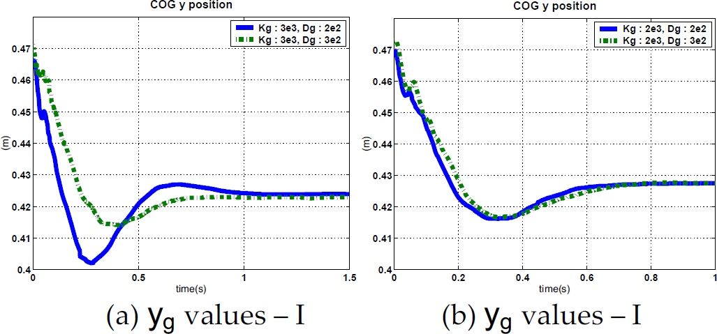
Drop landing experiment for four cases
We can see that both of cases show the body stiffness and damping behavior on landing according to given body behavior. The difference of steady state

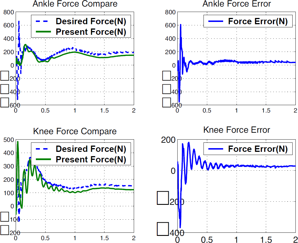
Actuator forces,
To see the effect of variable body stiffness and damping case, we used the result of Table. 3 which was calculated through the optimization process of section. 4. Initial body stiffness was selected as 1500N/m, 2000N/m and 2500N/m to see the various results with different values.
Body stiffness & damping values at experiments

Body stiffness & damping values at experiments
At Fig. 16, we can see the experimental and simulation results of

Drop landing for variable body stiffness & damping
Actuator force comparison of Case II in Table 3

Snapshots of landing experiment
This paper has presented body stiffness and damping controller for an articulated legged robot as a landing controller which resembles human's landing behavior. Body stiffness and damping behavior is realized through stiffness controller formulation about COG point and fast subsystem controller for flexible joints has been developed for PBOT model.
Through simulations and experiments, we have shown that landing motion for articulated legged system can be realized through body stiffness and damping control. We also have verified that variable body stiffness and damping case which is similar to human landing behavior is better for landing than constant value cases. Developed landing controller has an advantage that it does not require desired path and prior knowledge about impact time for landing motion but needs only desired body stiffness and damping values with position and velocity feedback.
Because we have used flat foot which has little damping materials beneath the foot, high frequency shock was not eliminated effectively which has produced fluctuation at actuator force control or rough force desired signal. To solve this problem, development of soft foot with arch structure is in work process. Also, developed body stiffness and damping controller is being applied to the development of controller for hopping motion of PBOT.