
Abstract
A three-linked manipulator mounted on a two-wheeled mobile platform is used to weld a long curved welding path. A welding torch mounted at the end of a manipulator of the welding mobile manipulator (WMM) must be controlled for tracking a welding path with constant velocity and constant welding angle of torch. In this paper, a decentralized control method is applied to control the WMM considered as two separate subsystems such as a mobile platform and a manipulator. Two decentralized motion controllers are designed to control two subsystems of WMM, respectively. Firstly, based on a tracking error vector of the manipulator and a feedback motion of the mobile platform, a kinematic controller is designed for manipulator. Secondly, based on an another tracking error vector of the mobile platform and a feedback angular velocities of revolution joints of three-link, a sliding mode controller is designed for the mobile platform. These controllers are obtained based on the Lyapunov's function and its stability condition to ensure for the tracking error vectors to be asymptotically stable. Furthermore, simulation and experimental results are presented to illustrate the effectiveness of the proposed algorithm.
Keywords
Introduction
Nowadays, the welding robots become widely used in the tasks which are harmful and dangerous for the welders. A good welding robot used in welding application can generates the perfect movements at a certain travel speed and reference welding angle of torch, which can produce a consistent weld penetration and weld strength. In practice, some various robotic welding systems have been developed recently. Kim, et al. (2000) developed a three dimensional laser vision system for an intelligent shipyard welding robot to detect the welding position and to recognize the 3D shape of the welding environments. Jeon, et al. (2002) presented the seam tracking and motion control of a two-wheeled welding mobile robot for lattice welding. The control is separated into three driving motions: straight locomotion, turning locomotion, and torch slider control. Ngo, et al. (2006) proposed a sliding mode control of two wheeled welding mobile robot for tracking a smooth-curved path.
As we know, the welding mobile robot (WMR) is more simple system than WMM. But its welding point has three degree of freedom (d.o.f.) which is under condition of nonholonomic system of a two-wheeled mobile platform. For this reason, the WMR cannot eliminate its tracking errors and satisfies the welding condition as the same time. It only achieves the welding condition when its tracking errors are zero.
To solve this problem, a WMM of three d.o.f. independent to its two-wheeled mobile platform is considered. The developed WMM consists of a three-linked manipulator plus a two-wheeled mobile platform (MP). The mobile manipulator is used for increasing the d.o.f. of the welding point. Hence it satisfies the constraints of the welding task. In this paper, the WMM is considered as two separate subsystems such as a MP and a manipulator. Two decentralized motion controllers are applied to control two subsystems of WMM, respectively. Based on a tracking error vector which is achieved from difference between a real posture of torch and its reference one, and feedback motions of MP, a kinematic controller is designed for manipulator to carry the welding torch for tracking a reference welding path with a constant velocity and a constant reference welding angle. The mobile platform is used to carry the manipulator to avoid its singularities. So the movement of the MP is specified. In this application, the MP is controlled by a sliding mode controller in order to make the manipulator's configuration return to its “good posture” configuration. The “good posture” of manipulator is defined in next section. Based on this idea, another error vector for a sliding mode controller of the mobile platform is obtained from difference between a real posture of the manipulator and its “good-posture”.
A developed WMM is shown in Fig. 1. The three-linked manipulator is mounted on the center of the MP. An angle sensor of link is attached at its revolution joint. The MP has more two passive wheels which are installed in front and rear at the bottom of MP for its balance, and their motion can be ignored in the dynamics. The motion of two wheels of MP is measured by rotation encoders. The touch sensor is fixed at the end of a third-link as shown in Fig. 1. The touch sensor rolls along a steel wall to detect the tracking errors. A simple way of measuring the errors by potentiometers is introduced in experimental result part. To illustrate the effectiveness of the proposed algorithm, simulation and experimental results are presented.

The welding mobile manipulator
Modeling of the mobile platform
Consider a WMM as shown in Fig. 2. It is model under the following assumptions:
The MP has two driving wheels for body motion, and those are positioned on an axis passed through its geometric center, The three-linked manipulator is mounted on the geometric center of the MP, The distance between the mass center and the rotation center of the MP is d. Fig. 2 doesn't show this distance. This value will be presented in the dynamic equation of MP. A magnet is set up at the bottom of the WMM to avoid slipping.

Scheme for deriving the kinematic equations of the welding mobile manipulator
In Fig. 2, (XP, YP) is a center coordinate of the MP, Φ
P
is heading angle of the MP, ω
rw
, ω
lw
is angular velocities of the right and the left wheels,
Consider a robot system having an n-dimensional configuration space with generalized coordinate vector
where
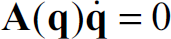
As a result, the kinematic model under the nonholonomic constraints in (1) can be derived as follows:

where
Firstly, the posture of MP for the center point P(X
P
, Y
P
) in the Cartesian space in Fig. 2 is defined as

If the mobile robot has nonholonomic constraint that the driving wheels purely roll and do not slip, A(q) in (1) can be expressed into

From (3) and (4), n = 3 and m = 1.
The velocity vector in (2) is defined as

In the kinematic model of (2),

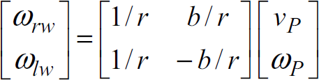
The relationship between v, ω and the angular velocities of two driving wheels is given by
In this application, the welding speed is very slow so that the manipulator motion during the transient time is assumed as a disturbance for MP. For this reason, the dynamic equation of the MP under nonholonomic constraints in (1) is described by Euler-Lagrange formulation as follows:

where
Differentiating (2), substituting this result to (8) and multiplying by

Multiplying by (

where

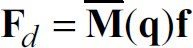
In practices, the dynamic equation of the MP under disturbance and interaction between the manipulator and the MP is expressed as follows:

where
where
In another hand, the dynamic equation of MP can be expressed by a feedback linearization of the system as follows (Yang and Kim, 1999)

where

Consider a three-linked manipulator as shown in Fig. 2. A new Cartesian coordinate frame (Frame x – y) is fixed on the mobile platform as shown in Fig. 2. The (Frame x – y) is called the moving coordinate frame because this coordinate frame is moved toghether with the mobile platform in the world coordinate (frame X – Y). The velocity vector of the end-effector with respect to the moving frame is given by

where
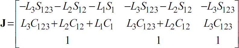
where L1, L2, L3 are the length of links of the manipulator, and
The dynamic equation of the end-effector of the manipulator with respect to the world frame is obtained as follows [Lewis, et al.]:

where

In this section, a decentralized control method is applied. A sliding mode controller and a kinematic controller are used to control the MP and the manipulator of WMM, respectively. The relationship between two controllers can be expressed as follows: Firstly, based on a tracking error vector which is obtained from difference between a real posture of torch and a reference one, and feedback motions of mobile platform, a kinematic controller is designed for the manipulator in order to move the welding torch tracking a welding path. Secondly, the mobile platform is used to carry the manipulator to avoid its singularities. So the movement of the MP is specified. For this reason, another error vector is obtained from difference between a real posture and the “good-posture” of the manipulator. Based on this error vector, a new sliding mode controller is applied to control two wheeled mobile platform. These controllers are obtained based on the Lyapunov's function and its stability condition to ensure for the error vectors to be asymptotically stable.
Kinematic controller design for manipulator
From Fig. 3, the tracking error vector

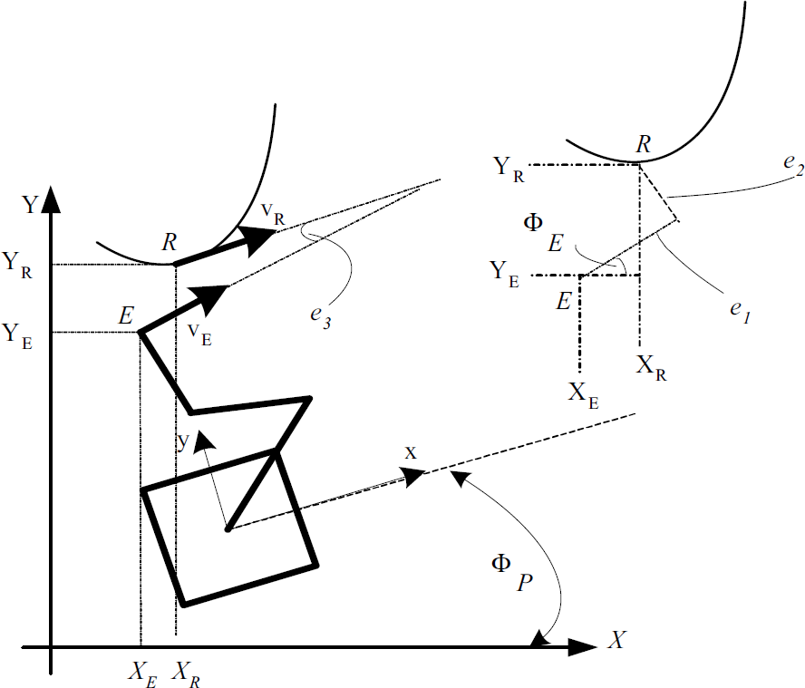
Scheme for deriving the tracking error vector
The tracking error vector can be rewritten in the matrix form as follows:

where PR = (XR YR Φ R ) T is a reference welding point which is moved along the welding path with a constant velocity and constant welding angle. PE = (XE YE Φ E ) T is a welding point or an end-effector point.
The first derivative of tracking error vector


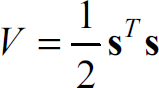
To obtain the kinematic controller a back stepping method is used. The Lyapunove function is proposed as follows:
The first derivative of

To achieve the negativeness of
where
Substituting (15), (17) and (20) into (24) yields

The error vector

The controllers vector
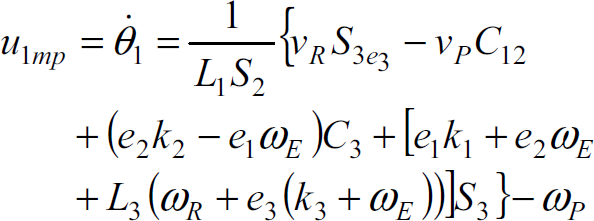
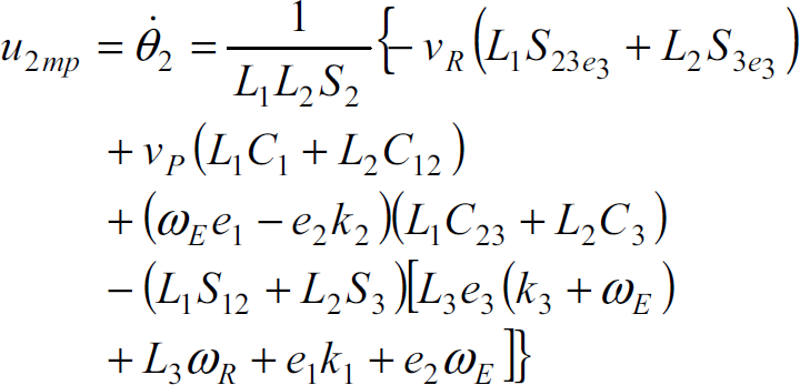

where S23e3 = sin(θ2 + θ3 + e3); S3e3 = sin(θ3 + e3)
In this part, a sliding mode is used to bring the configuration of the manipulator to “good posture”. The “good posture” of manipulator is chosen with θ1 = π/4, θ2 = π/2, θ3 = −π/4.
Let a point M(X
M
Y
M
Φ
M
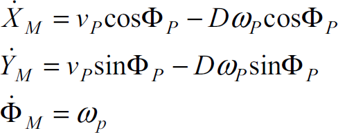
) is a fixed point with respect to the moving frame and is made by the “good posture” of the manipulator. A sliding mode controller is proposed to control the MP for the M point tracking the real reference E point. When the M point coincides with E point, that is it means that the manipulator has the good configuration for avoiding its singularity. Coordinate of the M point is expressed as follows:

where
The derivative of (30) is as follows
A new tracking error vector
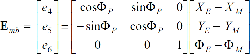
where Φ E = Φ r + e3.
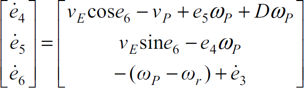
Let us denote that νP, ω
P
, νE and ω
E
are the linear velocity, the angular velocity of the MP, the linear velocity and the angular velocity of the end-effector with respect to the world frame, respectively. Then the derivative of MP error vector yields.
The following part presents a sliding mode controller vector
To design a sliding mode controller, the sliding surfaces are defined as follows:
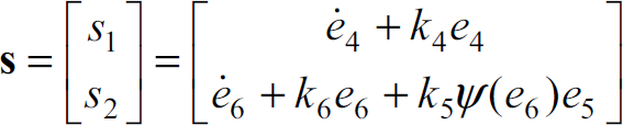
where k4, k5 and k6 are positive constant values. ψ(middot;) is a bounding function and is defined as follows:
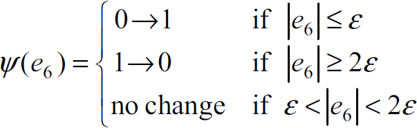
In (35) and Fig. 5, ɛ is a positive constant value. “No change” means that the value of ψ(·) function continuously keeps its value at e6 = ±ɛ or e6 = ±2ɛ before e6 enters into ɛ <|e6|< 2ɛ.

Scheme for deriving the MP tracking error vector
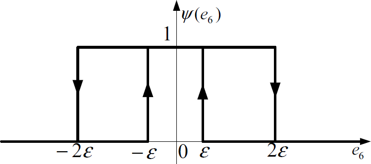
Characteristic of ψ(·) function
When the sliding surface vector is zero, the followings are obtained from the (32):


In (36), if e4 is positive, ė4 is negative, and vice versa. Thus, the equilibrium point of e4 converges to zero as t → ∞. It means that the error e4 → 0 as t → ∞ along the sliding surface (s1 = 0).
Because the configuration of the WMR has the M point which is located on the axis through the two contact points between driving wheels and floor, the error e5 can be eliminated via e6. For example, if e4 = 0 and e6 = 0, the value of e5 is constant from (33). For that result, the error e6 and its derivative in (37) cannot be zero in order to eliminate the error e5 when the error e5 ≠ 0.
In case of
To satisfy the Lyapunov's stability condition
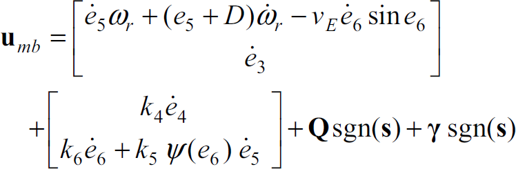
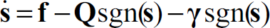
where γ = [γ1 γ2]T is a positive constant value and
Proof for Lyapunov's stability condition
Because the reference welding speed is constant

Using (14), (40) can be rewritten as follows:
From (38), (41) can be expressed as follows:
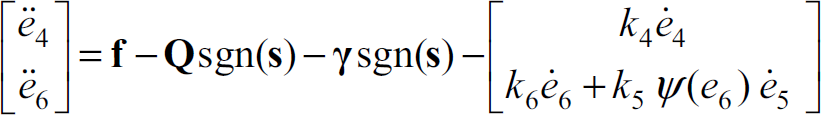
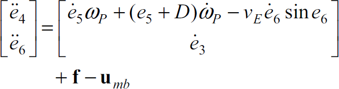
From (34), the first derivative of the sliding surfaces yields

From (41), the first derivative of the sliding surfaces can be rewritten as follows:
If

In practice, a chattering phenomenon in a sliding mode control can be eliminated by a saturation function. Using the saturation function, a thin boundary layer neighboring the switching surface is achieved, and then a smooth and proper controller can be obtained.
In this case, the welding velocity is rather slow, 7.5mm/s. Therefore, a thin boundary layer δ = 0.1 is chosen. A new smooth switching controller than previous switching controller in (39) can be obtained by substituting sign(•) function to sat(•) function in (39):
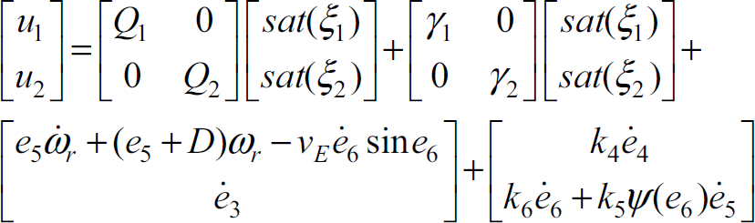
where the saturation function is defined as

With smoothing approach, the controller (39) can be implemented to the practice welding mobile robot totally. The effectiveness of the controller can be seen through the simulation and the experimental results.
Hardware design
Measurement of the errors e1, e2, e3
A simple measurement scheme is implemented using potentiometers to obtain the errors e1, e2, e3 as shown in Fig. 6. The experimental touch sensor is shown in Fig. 7. Two revolute potentiometers and one linear potentiometer are needed for measuring the tracking error vector. From Fig. 6, the tracking errors relations are given as

where r r is the radius of the rollers.

The scheme of measuring errors e1, e2, e3
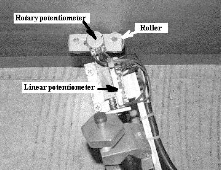
The touch sensor used in experiment
From Fig. 4, the tracking errors e4, e5, e6 with respect to moving frame can be calculated as follows:

where Φ E = Φ P θ1 + θ02 + θ3 – π/2
The joint angles θ1, θ2, θ3 can be determined from the angular sensors at revolute joint of links of the manipulator.
The schematic diagram for a decentralized control method is shown in Fig. 8. In this diagram, a relationship between controllers is illustrated by means of the output of this controller is one of the input ofanother controller and vice versa.

Schematic diagram of applied method
To verify the effectiveness of the proposed modeling and controllers, simulations and experimental results were done for the WMM with the welding reference trajectory as shown in Fig. 9. Numerical values and initial values used in simulation and experiment are shown in Table 1 and Table 2.

The WMM is tracking along the welding path
Numerical and initial values for simulation

Initial values for the simulation and experiment

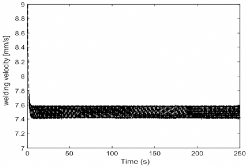
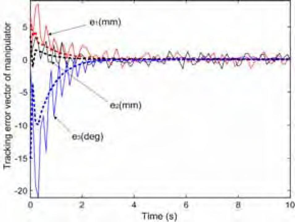
Fig. 10 shows the zoom out of the end-effector for tracking the welding path at beginning. Fig. 11 shows that, with the initial tracking error values e1 = 6mm, e2 = 4mm, e3 = −15 deg, the kinematic controllers of the manipulator makes this tracking error converge to zero after about 3 seconds in order to tracking the welding point. In this paper, decentralized motion control method is used, so to avoiding overshot between two controllers, the gain of controller of MP are chosen in order that a smooth welding speed is achieved. The tracking error vector [e4 e5 e6] T which is shown in Fig. 12 converges to zero slowly. This tracking error vector doesn't directly effect on the welding result. It only helps the manipulator to avoiding its singularity. With the movement of the MP, the angle of manipulator is converted and remained in the “good-posture” which is shown in Fig. 13. Fig. 14 shows that the sliding surface vector converges to zero and remains on it. Fig. 15 shows the angular velocities of right wheel and left wheel obtained by the sliding mode controller. Fig 16 shows the linear velocity of end-effector is remained at 7.5 ± 1 [mm]. So this welding speed is good enough for achieving a good welding result. Fig. 17 shows the simulation and experiment results of the tracking errors [e1 e2 e3] and those errors are bounded. And their average value converges to zero. Fig. 18 shows the simulation and experiment results of the tracking errors [e4 e5 e6] and those errors are bounded and also converge to zero smoothly.
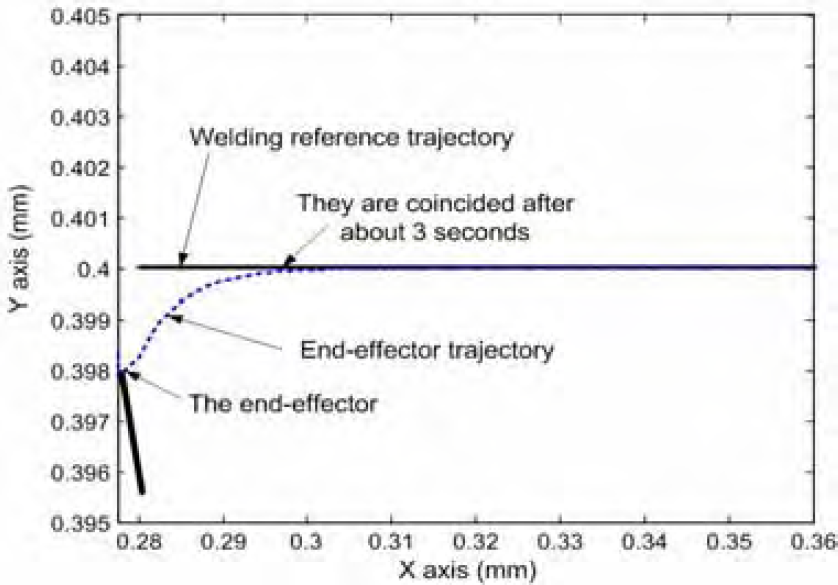
Trajectory of the end-effector and its reference at beginning
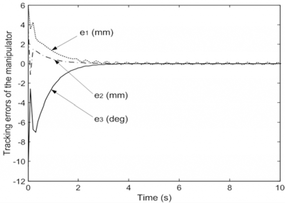
Tracking errors e1 e2 e3 at beginning
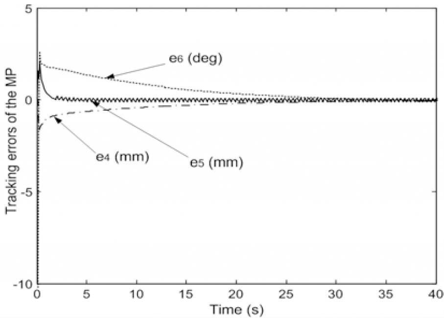
Tracking errors e4 e5 e6 at beginning

Angular of revolution joints θ1 θ2 θ3
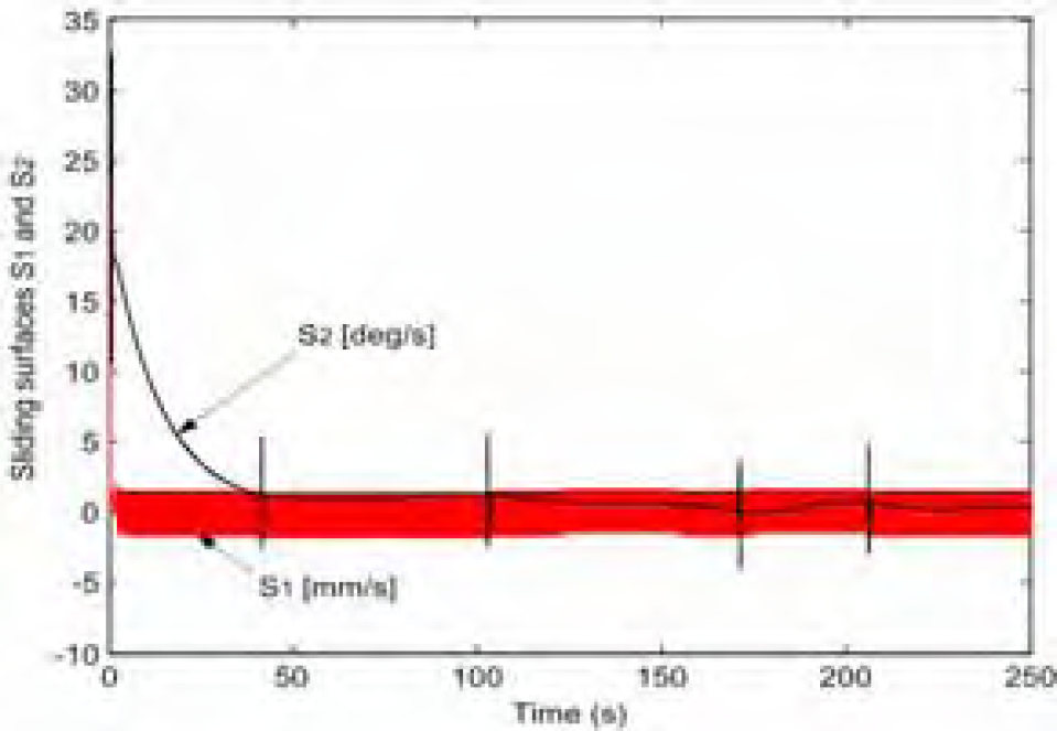
Sliding surfaces s1 s2

Linear and angular velocities of MP
Linear and angular velocities of welding point
Simulation and experimental results of e1 e2 e3 at beginning

Smulation and experimental results of e4 e5 e6 at beginning
This paper developed a WMM which can co-work between mobile platform and manipulator for tracking a long smooth curved welding path. The main task of the control system is to control the end-effector or welding point of the WMM for tracking a welding point which is moved on the welding path with constant velocity. Furthermore, the angle of welding torch must be kept constant with respect to the welding curve. The WMM is divided into two subsystems and is controlled by decentralized controllers. The kinematic controller and sliding mode controller are designed to control the manipulator and the mobile-platform, respectively. These controllers are obtained based on the Lyapunov's function and its stability condition to ensure the error vectors to be asymptotically stable. Furthermore, simulation and experimental results are presented to illustrate the effectiveness of the proposed algorithm. (This work was supported by Pukyong National Uni. Research Foundation Grant in 2005 (0010000200501700)