
Abstract
Finger prostheses are devices developed to emulate the functionality of natural human fingers. On top of their aesthetic appearance in terms of shape, size and colour, such biomimetic devices require a high level of dexterity. They must be capable of gripping an object, and even manipulating it in the hand. This paper presents a biomimetic robotic finger actuated by a hybrid mechanism and integrated with a tactile sensor. The hybrid actuation mechanism comprises a DC micromotor and a Shape Memory Alloy (SMA) wire. A customized test rig has been developed to measure the force and stroke produced by the SMA wire. In parallel with the actuator development, experimental investigations have been conducted on Quantum Tunnelling Composite (QTC) and Pressure Conductive Rubber (PCR) towards the development of a tactile sensor for the finger. The viability of using these materials for tactile sensing has been determined. Such a hybrid actuation approach aided with tactile sensing capability enables a finger design as an integral part of a prosthetic hand for applications up to the transradial amputation level.
1. Introduction
Current upper extremity prostheses are having a hard time meeting the expectations of upper-limb amputees. A substantial proportion of them avoid the use of their prostheses due to the limitations of current commercial devices, for instance they are too heavy, bulky, noisy and lack tactile feedback. Designing an actuator for hand prostheses is a challenge because it must accommodate the space and weight constraints of the fingers and palm, and yet meeting the requirements for the grip force and grasp speed. Besides utilizing body power [1–3], conventional actuators used in upper extremity prostheses are DC motors [4–8]. Despite being able to produce the high torque and efficiency required for the kinematic performance, the noisy operation and limited energy density of such motors leads to the use of bulky and heavy driving systems [9].
Biologically, the flexors are used to close the fingers to grip an object while the extensors are used to open the hand again [10]. Alternative actuation technology, such as SMA wires which contract to produce actuation forces, offer potential advantages for an actuation mechanism resembling the biological muscle. Besides a silent operation, smooth and extremely high force to weight ratio, SMA enables a compact and lightweight actuator design. However, they suffer from s relatively slow response rate and temperature sensitivity. To overcome the trade-off between dexterity and anthropomorphic size, weight and appearance, a hybrid actuation system is proposed for finger prostheses. Such a hybrid actuation mechanism synergizes the advantages of a DC micromotor and a SMA actuator to resemble both the key physical features and grasping functionality of a biological finger.
Sensors employing resistive, capacitive, inductive, optical, magnetic, piezoelectric, ultrasonic and magnetoelectric characteristics are the most widespread sensors in robot hands [11]. Other new materials such as the Quantum Tunnelling Composite (QTC) [12] and Conductive Rubber [13–14] have also been used for tactile sensing. Hence, the work herein aims to explore the properties of conductive rubber for tactile sensing by making a comparison study on the resistance behaviour of the conductive rubber to that of the QTC using experimental techniques on a fanning strip sensor board with different separation paths. The most suitable material will be used for the tactile sensor development.
Figure 1 shows a schematic overview of the actuators and sensors of the finger prosthesis.
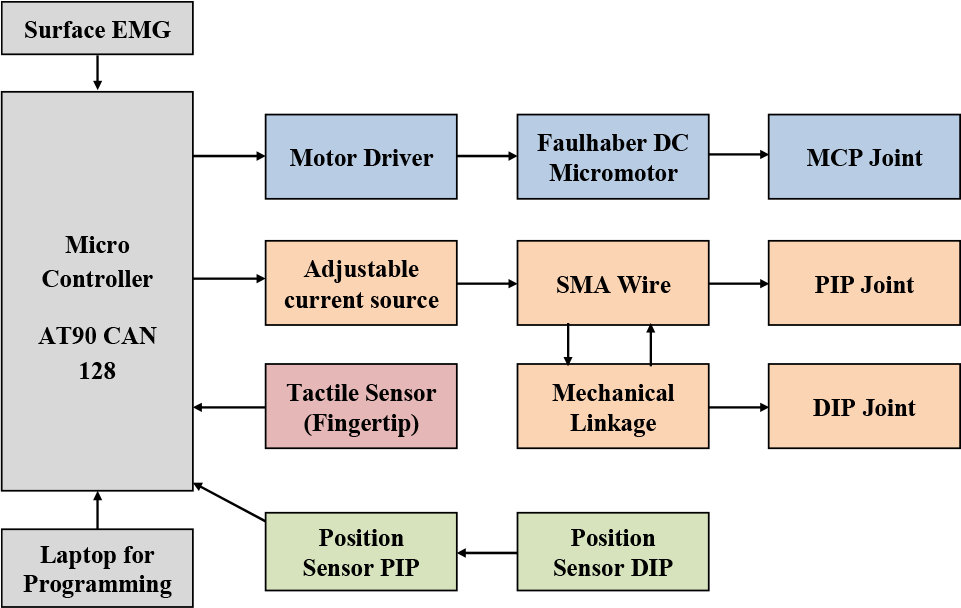
Schematic overview of actuators and sensors.
This paper emphasizes the design of finger movement for a serial link mechanism based on hybrid actuation of a DC micromotor and SMA wire. The MCP joint of the prosthetic finger will be actuated with a Faulhaber DC micromotor. The other two joints, the PIP joint and the DIP joint, are mechanically linked. They will be actuated by an SMA wire. SMA wire performance characteristics were assessed with a special test rig. In addition, this work also aims to integrate a customized tactile sensor to facilitate better grasping of objects. At the fingertip, a customized tactile sensor is integrated to detect an object and provide feedback to the controller to limit the torque of the DC micromotor. During the design process, it takes a number of phases to come out with a unique design and function, especially when dealing with a small compact machine, while ensuring that they agree to engineering requirements.
2. Kinematic Analysis
The science of grasping and manipulation serves as the basis for the current finger design. The prototype of finger prosthesis is a three-link serial mechanism with a Degree of Freedom (DOF) at the Metacarpophalangeal (MCP) and Proximal Inter-phalangeal (PIP) joints. The Distal Interphalangeal (DIP) joint is coupled with the PIP joint by means of mechanical linkages at an angular displacement ratio of 0.818. It is not considered as a DOF as a distinct set of movements that can be described by a single parameter is only considered a single DOF [15]. A schematic of the finger lying on the X-Y plane with the MCP joint fixed to the palm is shown in Figure 2. The finger phalange and joint parameters are tabulated in Table 1.

Coordinate frame for the analysis of finger kinematics.
Parameters of Finger Phalanges.

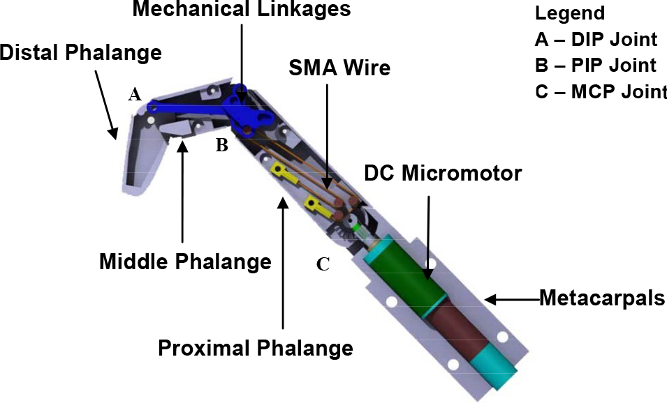
The kinematic behaviour of the finger prosthesis is analysed using the Denavit-Hartenberg method. The method determines the position and orientation of the fingertip as a function of joint angle θi, phalanx offset di, phalanx length li and phalanx twist αi. Since the abduction-adduction of the MCP joint is ignored, phalanx offset di and phalanx twist αi are eliminated. Taking into consideration that the DIP joint (θ3) is a passive joint coupled with the movement of the PIP joint angle (θ2); the forward kinematic of the finger for three DOF is computed.


and θ is known as:
However, the DIP joint is a passive joint in which, the angle of θ3 is axis mechanized by the movement PIP joint angle (θ2) at a ratio of 0.8182.


The working envelope for the prosthetic finger is obtained from the kinematic analysis and plotted using MATLAB, as show in Figure 3. The working envelope illustrates all positions reachable by the fingertip. It covers a range of movement similar to that of the author's middle finger and hence is able to enable the functionality close to that of a biological human middle finger.

Working envelope for the fingertip of the middle finger.
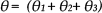
The grasping characteristic of the finger prosthesis is developed by imitating the object geometry. The phalanges will rotate at normal speed and stop as they come into contact with the object and the reacting torque is sufficient enough to stop the phalanges' rotation. This method enables the finger prosthesis to adapt to various object geometries. This approach also reduces the complexity of controlling the movement of the finger phalanges. Figure 4 illustrates the phalange motion in order to grasp cylindrical and spherical objects by imitating the circular geometry.
Grasping by imitating the object geometry.
3. Hybrid Actuation Mechanism
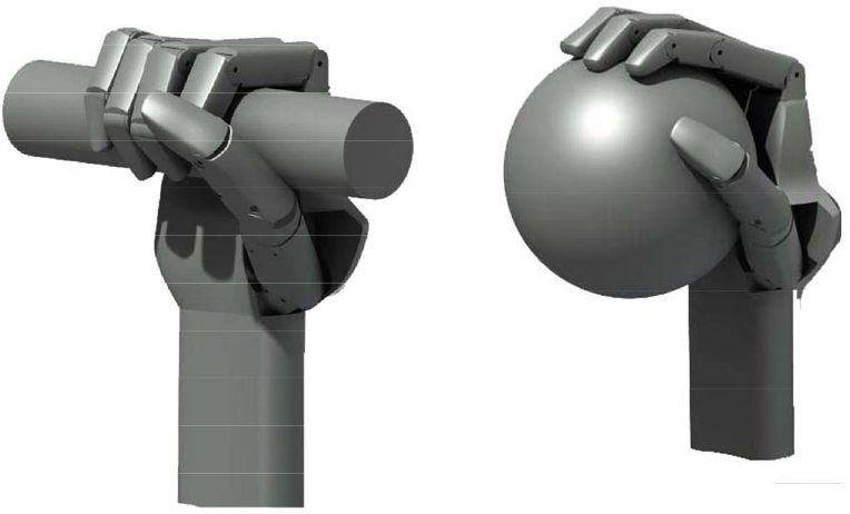
A hybrid mechanism taking advantage of both the DC micromotor and the SMA wire has been developed for the finger prosthesis. Its internal structure is shown in Figure 5.
Internal structure of the hybrid-actuated finger prosthesis.
A DC micromotor and a SMA wire are used to actuate the MCP joint and the PIP joint independently. The DIP joint rotates in correspondence to the PIP joint rotation by means of crank linkages. The MCP joint can be rotated without forcing the PIP joint to rotate along and vice versa. The MCP joint is actuated by a Faulhaber DC micromotor and thus providing a precise and accurate control at the MCP joint. A combination of a spur gear and a crown gear enables this joint to transmit torque from the motor to the proximal phalange at a right angle with a gear ratio of 5:1. Hence, the generated torque is enhanced. A stopper is designed at both ends of a 0° and 90° angle to avoid the proximal phalange to rotate beyond this range.
When the SMA wire is heated, the middle phalange rotates inwards. A grade of SMA wire known as Flexinol is used as an actuator at the PIP joint, mainly due to the limitation of space here. Since the contraction of the wire is limited, a direct actuation approach will not be able to produce a 110° rotation at the PIP joint. Therefore, a gear set with a ratio of 1:2 is used to amplify the degree of rotation. The DIP joint consists of a driven pulley, a linkage and a connecting bar. The driven pulley is the distal phalange itself. As the middle phalange rotates, the connecting bar will push the distal phalange to rotate along. A torsion spring is attached at this joint, which is used to reverse the motion when no current is supplied through the SMA wire.
Currently two finger prostheses have been produced, as shown in Figure 6. The weight of the finger, which is a middle finger, together with SMA wire and Faulhaber DC micromotor is 58g. In comparison, the human hand has an average weight of 400g [15] (distal to the wrist and not including the forearm extrinsic muscles). A Faulhaber motion manager program is used to control the Faulhaber DC micromotors with sequential programs. A PC serial communication, which converts USB protocol to RS232, connects the laptop with the Faulhaber motion controller, whereas a 100 watt power supply supplies voltage and current at 24 VDC and 4.2 A respectively to the motion controllers as well as the DC micromotors. The GUI shown in Figure 7 was developed using Visual Basic to enable independent motor control. There are three possible modes of operation, i.e., fully open posture (0°), partially closed posture (45°) and fully closed posture (90°).
SMA has two types of temperature dependent phases: the martensite, which is weak and stable at a lower temperature and the austenite, which is strong and stable at a higher temperature. As the temperature rises, martensite transforms to austenite and as the temperature decreases, the reverse transformation occurs. It is notable that during the phase transformation, SMA is capable of generating a large force associated with up to 5% strain recovery, which enables it as an actuator. An experiment setup, as shown in Figure 8, has been constructed to assess the relationship between the stroke produced by a SMA wire and the required contraction time for varying energizing currents. The stroke of an SMA wire is measured as a percentage of the length of the wire. The experimental setup consists of a workstation, a data logger and a power supply.
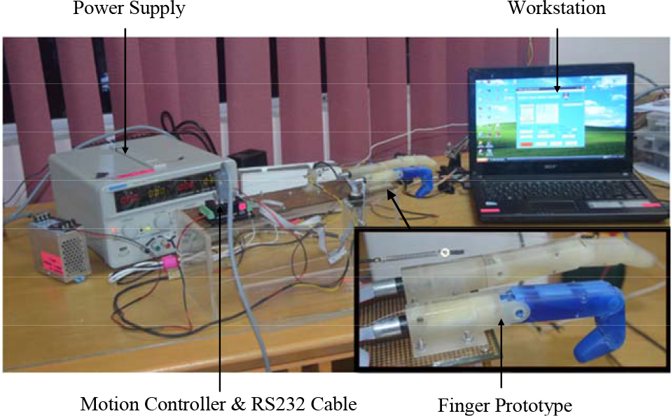
Application for finger prototype.

Graphical User Interface (GUI) to actuate the motor.

Experimental setup to assess SMA wires.
4. Assessment of SMA Wires
The test rig consists of a linear potentiometer by K. FADER, a fixture, a bias spring and an SMA wire. In this experiment, a Flexinol Ni-Ti wire of length 115mm with a diameter of 0.508mm was used. The linear potentiometer is set horizontally with the bias spring attached to the linear potentiometer at the other end of the rail. As such, an opposing force is exerted on the wire constantly by the bias spring. If no opposing force is exerted, very little stretch can be observed during cooling and correspondingly very little contraction can be obtained upon heating. The experiment is conducted at room temperature.
The Flexinol Ni-Ti wire with properties as shown in Table 2 was chosen because the wire has a high resistance compared to copper and other conductive materials and ready-to-use characteristics compared to ordinary Nitinol such as Cu-Zn-Al and Cu-Al-Ni. The Ni-Ti can be easily heated by a direct current and its contraction ranges between 3%-4% and can store up to approximately 14% depending on the arrangement of the wire [16].
Nickel-Titanium Alloy Physical Properties [16].

4.1 Impact of Bias Force
A bias force will have a substantial impact on the characteristics of the SMA wire during the heating process and the cooling process. Concepts of bias force can be understood by looking at Figure 9. Each wire is connected to a bias spring and the force produced will be measured using a load cell at the end of the spring.

Concept of bias force.
In order to investigate the impact of the bias force, two experimental setups were used. In the first setup, no bias force was applied to the SMA wire. In the second setup, a bias force ranging from 11N to 13N was applied to the SMA wire by means of a normal bias spring. Figure 10 shows the behaviour of the SMA wire when it is heated up using a direct current of 3.2A and 2.8V for 15 seconds with the bias forces applied and then cools down naturally by cutting off the power supply.
When the SMA wire heats up, as shown in Figure 11, it can be observed that a greater contraction stroke can be obtained when a bias force is applied to the wire. Increasing the bias force from 11N to 12N, the contraction stroke increases from 3.4% to 3.8%. Nevertheless, when increasing the bias force further to 13N the contraction stroke remains at 3.8%. When the SMA wire cools down, it can be observed that a higher cooling rate can be obtained if a bias force is applied to the SMA wire. Furthermore, it can be observed that the SMA wire did not return back to its original length completely without a bias force. It can be concluded that the bias force helps to pull the SMA wire back to its original length and reduces the required time during the cooling process. Precaution should be taken as too large a bias force will result in damage to the wire due to permanent elongation.

Contraction and relaxation of SMA wire subjected to varying bias force.

Contraction response of SMA wire within 0–15 seconds subjected to varying bias force.
4.2 Impact of Input Current
Since the SMA wire is thermally activated, its characteristics are influenced by the input current. The SMA wire was exerted with a 12N bias force and heated up using a direct current of 2.4A to 3.4A and 2.8V for 15 seconds. The stroke and force produced as a result of the contraction of the wire during the heating process were measured and analysed shown in Figure 9 and Figure 10. It can be observed that by increasing the input current from 2.4A to 3.4A, the contraction stroke increases from 3.3% to 4.1%, as shown in Figure 12, while the contraction force increases from 36.9N to 38.2N as shown in Figure 13. From the measurement result, it can be seen that the time taken to reach the maximum force and stroke decreases as the energizing current increases from 2.4A to 3.4A. It can be concluded that the higher the amperage, the faster the wire contracts as the rate of contraction is influenced by the rate of heating. The same test was repeated on SMA wires with a diameter of 0.0381mm and 0.0254mm. Table 3 shows the current setting for three SMA wires of different diameters, which produce an optimum contraction of the wire.
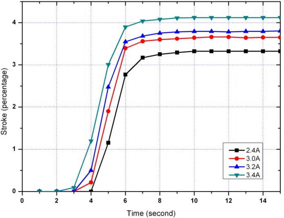
Stroke produced by a SMA wire during contraction subjected to varying input current.
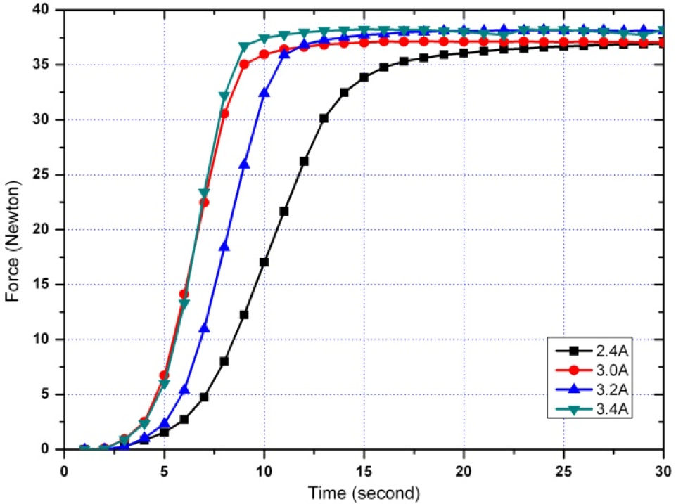
Force produced by a SMA wire during contraction subjected to varying input current.
Optimum current setting for different wire diameters.

4.3 Improvement of SMA Wire Cooling Rate
If higher stresses or stains are imposed, then the memory strain is likely to slowly decrease and good motion may be obtained for only hundreds or a few thousands of cycles. The permanent deformation, which occurs in the wire during cycling, is a function of the stress imposed and the temperature under which the actuator wire is operating. Flexional wire has been specially processed to minimize this straining, but if the stress is too great or the temperature too high some permanent strain will occur [17]. To improve the cooling rate, additional methods of cooling using forced air, a heat sink, increased stress and liquid coolant can be attempted [16]. However, not all the listed ways are practical for use to control the temperature in SMA wires as it depends on the application. As a consequence, only two methods were chosen for this experiment, the heat sink and the bias force method. In this experiment, it was proven that the method of microstructure stress caused wires changes when excessive force was used. In addition, when more force was applied to the wire, it was more difficult for SMA wires to return back to their original length.
The proposed heat sink consists of two plates, where the SMA wire was sandwiched between the plates, as shown in Figure 14. In the figure, the heat dissipation that occurred between the SMA wire and the heat sink is illustrated. Thermal grease is added to provide an extra cooling effect. It is then heated by a direct current from the power supply. The test was conducted using an SMA wire of 0.0508mm diameter. Three different current settings, 2400mA, 2600mA and 2800mA, were used. The two types of material for the heat sink were brass and aluminium, with thermal conductivity λ of 109 W/m.K and 222 W/m.K, respectively. The plates were 5.1mm high, 13mm width and 100m long.

Cross sectional diagram of heat dissipation.
Through observation, the presence of the heat sink improves the cooling rate of the SMA wire. The SMA wire was able to cool back to an ambient temperature more quickly. As indicated in Figure 15, aluminium works better as a heat sink in comparison to brass. In this test, the SMA wire was heated by a direct current of 2600mA supplied by the power supply. The wire was 0.0508mm in diameter and 115mm long. In addition, aluminium is much lighter than other materials for usage in finger prosthesis.

The impact of heat sink on SMA wire.
5. Tactile Sensing Methods
Robots should be able to recognize normal and shear forces in order to grasp objects securely. For this reason, different methods of tactile sensing are developed to assist in the grasping mechanism. At the current time; sensors employing resistive, capacitive, inductive, optical, magnetic, piezoelectric, ultrasonic and magnetoelectric characteristics are the most widespread sensors in robot hands [17]. There are also tactile sensors manipulating physical inputs such as force and pressure [18, 19]. New materials such as the quantum tunnelling composites (QTC) have been used for tactile sensing in the Shadow Dexterous Hand [12, 20]. In recent years, there have also been attempts to develop new tactile sensing methods using conductive rubber [13, 14].
Conductive materials such as the quantum tunnelling composites (QTC) have been used for tactile sensing in the Shadow Dexterous Hand [12, 20]. It is an insulator that has the ability to transform to a metal like conductor when compressed, twisted or stretched. This technology enabled the construction of the fingertip tactile sensing of the Shadow Hand with 34 tactile regions in the tip area. The sensitivity of the sensing ranges from 3KN/m2 (equivalent to a 3g weight applied to a single sensing region of 10mm2) up to 400KN/m2. Another work using QTC-based tactile sensing for a robot hand is reported in [21]. A similar insulator turned metal like conductor when compressed or stretched is pressure conductive rubber (PCR). PCR sheet is integrated with organic transistors to realize a practical artificial skin in [13]. A tactile sensor using PCR is developed in [14]. The PCR is stitched with electrical wires in a matrix array of 3 × 16. The sensor was tested on a four-fingered robot hand to verify its effectiveness. The structure and principle of the operation of the pressure conductive tactile sensor is also outlined by the authors in [22].
While both QTC and PCR have been reported as realizable tactile sensing materials; their characteristics have not been compared in terms of their resistance property. Thus, the work herein endeavours to explore the resistive properties of both PCR and QTC for tactile sensing by making a comparison study of the resistance behaviour of both materials to ascertain the most suitable material to be used on a fanning strip sensor board.
To assist the biomimetic finger prosthesis in tactile sensing, preliminary experiments were conducted concurrently with finger development to explore the properties of QTC and PCR. The properties of pressure conductive rubber (PCR) were studied by making a comparison study of the resistance behaviour of the conductive rubber to that of the QTC using experimental techniques. This was done on a fanning strip sensor board with different separation paths. The purpose of the experiment is also to decide on the best separation path between strips on a sensor board with a fanning strip structure (a combed like structure board). Consequently, the control strategies are proposed and simulated.
Hence, this study aims to ascertain the viability of using either PCR or QTC for tactile sensing in the setup mentioned. The first task in the investigation is to establish the properties (resistance over pressure) of the conductive materials. As mentioned, the QTC pills and PCR will be compared by the resistance property of PCR and QTC to ascertain the viability of both materials with a combed like structure board. Secondly, the study will help to determine the best separation distance of the conducting paths on the sensor board for the most viable material.
5.1 Experimental Setup for Tactile Sensing
Resistance measurements were carried out to establish the properties of PCR and QTC pills materials. The resistance behaviour of both materials could be established under different pressures. The experimental setup to investigate the resistance behaviour is shown in Figure 16. Aluminium is used to construct the conducting contact surfaces. The separation distances between the conducting contact surfaces are set at 0.5mm and 0.25mm respectively. This actually represents the distance of the individual conducting paths on the sensor board. The different separation distances should make it possible to determine what influences the separation distances the conducting paths have on resistance measurements. A 1cm2 PCR was laid above the separation gap between the contacts on the aluminium foil in the measuring setup sets for different contact surface distances. A transparent film was used as an insulation material and loads ranging between 100g and 1000g are applied (forces ranging 0.98N to 9.8N). Resistances changes across the contact surfaces were recorded using a multimeter for the different loads applied. The same setup was also used for establishing the properties for the QTC pills. With the experimental procedures outlined above, resistance behaviour of the two materials under different pressures and for two different separation distances could be established.
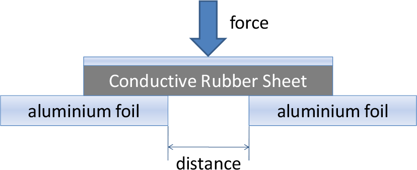
Experimental setup for assessment of PCR and QTC.
5.2 Investigating Resistive Property of PCR and QTC for 0.5 mm and 0.25mm Separation Distances
To obtain the resistance behaviour of both materials, three series of resistances readings for loads of 100g to 1000g in increments of 100g were obtained. The resistance values were then converted to a logarithmic scale. The use of the logarithms of the resistance values rather than the actual values reduces the wide range of resistance values to a more manageable size. Thus, the log resistances versus the weight were plotted for both PCR and QTC for contact distances of 0.25mm and 0.5mm respectively in Figure 17. From Figure 17, the resistance values established for the PCR were not reproducible based on the fact that all three series of plot for both Figure 17(a) and (b) did not coincide with each other. On the other hand, resistance measurements of the QTC pills show stable and reproducible values. The plots in Figure 17(c) show a high degree of coincidence for the QTC on a separation gap of 0.25mm. Figure 17(d) shows the highest coincidence between the plots for the QTC on a separation gap of 0.5mm.
It can be concluded from the results that QTC is more suitable as a material for tactile sensing compared to PCR, which demonstrates variations in resistances under constant pressure. For further development of the project, QTC pills should be used for the sensor. As for the QTC pills, a higher sensitivity could be achieved with a distance of 0.5mm between conducting paths.
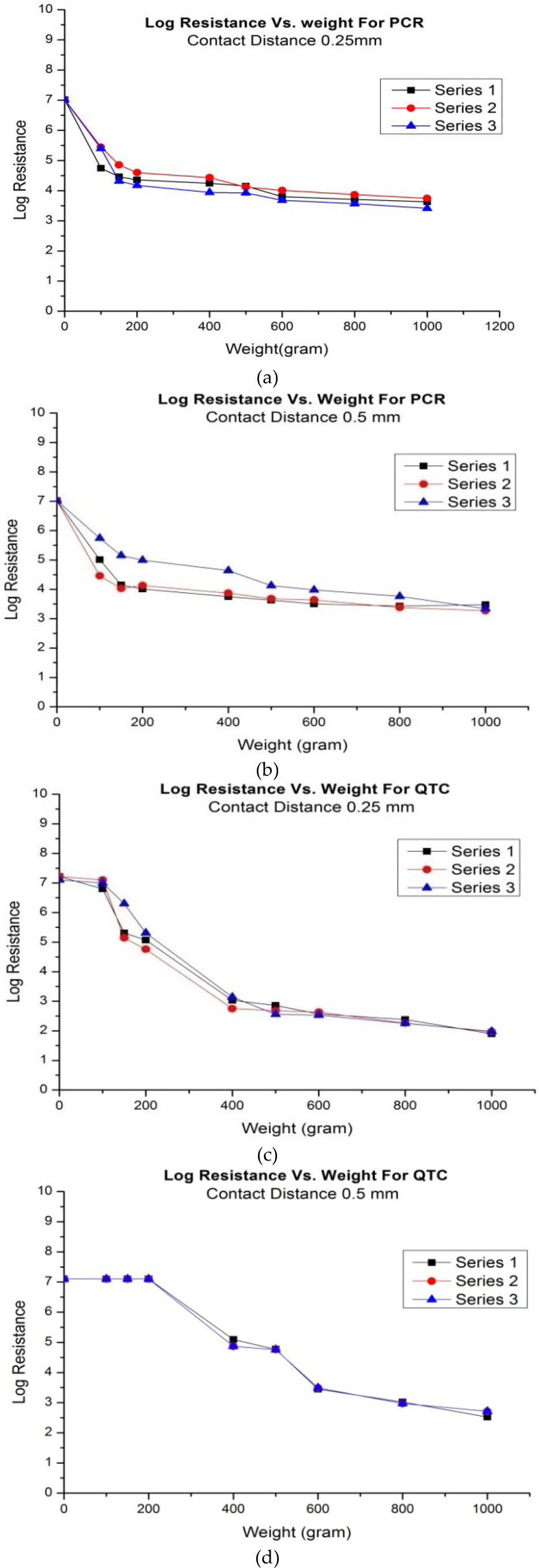
Log resistances behaviour versus weight for CRS and QTC materials.
5.3 Integration of Tactile Sensor into Finger Surface
A schematic setup for the tactile sensor is suggested in Figure 18. The sensor board comprises a sensor array with 16 elements. Hence, 16 QTC pills can be placed on this array structure. An Arduino Duemilanove microcontroller is employed to control the multiplexer and to capture voltage readings induced by resistance changes across the array of elements when the respective QTC pills experience external pressure. The microcontroller also functions to communicate with the desktop or laptop. A fanning strip design is employed to develop the sensor board. This kind of matrix like design is also implemented in [22–23] and is recommended for measurement with CRS in [24]. Here, the trace width consists of 0.3mm and the distance between the individual conducting paths is 0.5mm. The board is constructed in such a way so that 16 elements could be arranged on the sensor board. The total size measures 1.8cm × 1.5cm × 0.5mm, which constitutes precisely the fingertip of the robot hand.
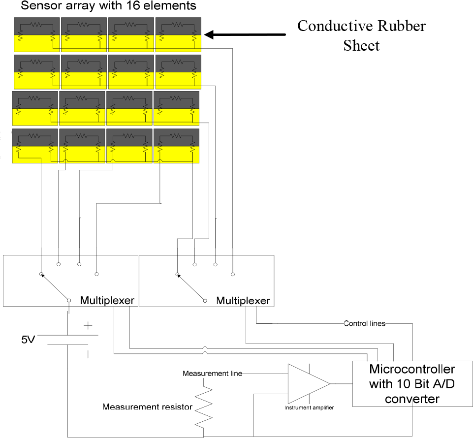
Schematic diagram of tactile sensor.
Figure 19 shows the structure of the tactile sensor. The QTC material is located in between a protective gel and the fanning strip sensor board. The contact surface of the board is manufactured in silver to provide them with better protection against oxide build-up. All 16 elements on the sensor board are steered for the measurement of their individual values with two multiplexers over a precision resistor. The steering of the two multiplexers is executed sequentially by the microcontroller until all 16 individual element values are captured and recorded. A resistance is switched in parallel. In addition to this, the measurement signal was enhanced via an instrument amplifier INP110KP. A “scanning” algorithm is developed and was successfully simulated using the “Arduino Alpha” software for the microcontroller. The algorithm controls both the multiplexers for the readout of the tactile sensor's 16 elements. The multiplexers are required for tripping the sensor arrays. Sixteen readouts are needed where all the elements of a 4×4 array will be read.

Sensor board design and structure of tactile sensor.
6. Conclusion
A hybrid actuation system comprising a Faulhaber DC micromotor and a Nitinol (Ni-Ti) SMA wire has been developed for the flexion-extension of a customized finger prosthesis. Kinematic analysis shows that the design achieves the range of movements of the human counterpart and hence closely resembles its functionality. Particularly, the contraction displacement and force generated by the SMA wire as well as its response were studied under varying input currents. In order to realize the tactile sensing functionality of the finger, the resistive properties of PCR and QTC have been assessed. The QTC has been identified as a more viable material for the fanning strip sensor board. The schematic design, sensor board design and the sensor structure have been presented. The sensor will give a feedback to the controller so that the robotic finger will grab the object placed in the robotic hands.
The hybrid actuated finger prosthesis aided with tactile sensing capability was developed as a part of a prosthetic hand for higher amputation levels. In the future, the hybrid actuator will be controlled by myoelectric sensors to produce useful patterns of finger movements. The electrical activity generated by contracting muscle in the forearm will be used as a control input signal for the prosthetic fingers. The myoelectric signal will be monitored using surface electromyography sensors. These sensors are planned to be placed on the thickest muscles of the forearm, which are the extensor carpi radialis longus and flexor carpi ulnaris.
Footnotes
13. Acknowledgements
This project is funded by the Ministry of Higher Education Malaysia under grant number 600-RMI/ERGS 5/3 (23/2011) and the Ministry of Science, Technology and Innovation Malaysia under grant number 02-01-01-SF0142.