
Abstract
In this paper we suggest an entirely new strategy for the dexterous manipulation of a linear flexible object, such as rope or a cable, with a high-speed manipulator. We deal with a flexible rope as one example of the linear flexible object. The strategy involves manipulating the object at high-speed. By moving the robot at high-speed, we can assume that the dynamic behaviour of the flexible rope can be obtained by performing algebraic calculations of the high-speed robot motion. Based on this assumption, we derive a dynamic deformation model of the flexible rope and confirm the validity of the proposed model. Then we perform a simulation of dynamic, high-speed knotting based on the proposed model. We also discuss the possibility of forming the knot based on a simple analysis model. Finally, we show experimental results demonstrating dynamic, high-speed knotting with a high-speed manipulator.
1. Introduction
Object manipulation is an extremely important problem in the robotics field and many researchers have proposed manipulation techniques for achieving various tasks.

Comparison of types of manipulation
In this section, we discuss past robotic manipulation techniques and we identify a critical problem to be solved in robotic manipulation.
1.1 Robotic manipulation
We divide robotic manipulation tasks into two aspects: the manipulation methods and the target objects. Manipulation methods are categorized into static manipulation and dynamic manipulation, and the target objects are categorized into rigid objects and flexible objects. As a result, robotic manipulation can be divided into four types, as shown in Fig. 1: static manipulation of a rigid object, static manipulation of a flexible object, dynamic manipulation of a rigid object and dynamic manipulation of a flexible object. In the following, we discuss representative methods of achieving these manipulations.
As described above (Fig. 1), static manipulation of rigid and flexible objects and dynamic manipulation of a rigid object have already been achieved. Until now, however, the dynamic manipulation of a flexible object has not been realized. Thus, we consider that an effective strategy and control method for the dynamic manipulation of a flexible object should be proposed in order to improve the manipulation ability.
High-speed manipulator
1.2 Dynamic Manipulation of a Flexible Object
The main issue faced in dynamic manipulation of a flexible object is:
deformation of the object during manipulation. Associated difficulties are:
the difficulty of estimating the object's deformation
the difficulty of modelling the object's deformation.
We expect that research on this kind of manipulation will be stimulated by proposing a method that solves these difficulties. As one solution, here we consider high-speed motion and high-speed sensory feedback. With this approach, motion planning of the high-speed robot in particular is extremely important.
Many motion planning methods for flexible manipulators have been suggested. For instance, Arisumi et al. proposed casting manipulation [14], Yahya et al. performed motion planning based on a geometrical method [15] and Mohri et al. executed efficient motion planning using a performance index [16]. However, these researchers did not discuss motion planning for achieving manipulation tasks of a flexible object.
Therefore, we propose a novel strategy using the high-speed motion of a manipulator to solve the above problems. By exploiting the high-speed motion, we assume that the rope deformation can be derived algebraically from the robot motion. The goal of this study is to show that the model and the control method of a linear flexible object can be simplified by using the high-speed performance of the robot and sensors. Furthermore, we suggest a motion planning method based on the proposed method. Using this approach, we demonstrated dynamic, high-speed knotting of a flexible rope as a concrete example of dynamic manipulation of a flexible object [13].

Dynamic, high-speed knotting by a human subject
2. System Configuration
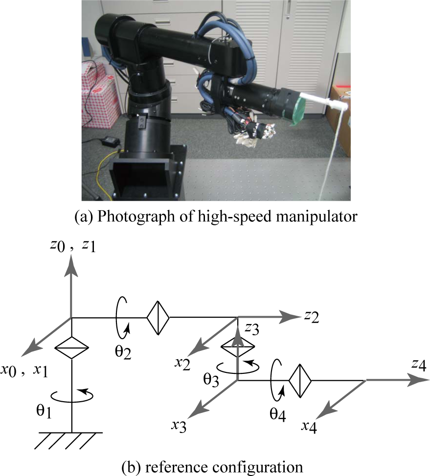
Fig. 2(a) shows a photograph of the high-speed manipulator. The manipulator has five degrees of freedom, including the oblique axis, the rotation axis (θ1) of the upper arm (shoulder), the circulation axis (θ2) of the upper arm, the rotation axis (θ3) of the lower arm (elbow) and the circulation axis (θ4) of the lower arm. The actuators are high-power devices designed for realizing high-speed movement; for example, the maximum velocity of the elbow is 15.83m/s and the maximum velocity of the end-effector is 27.22m/s. Since the velocity of the human arm (elbow) is about 6–10m/s, the motion of the manipulator is as fast and flexible as human motion.
Fig. 2(b) shows the kinematics and the base coordinates of the manipulator, with the exception of the oblique axis. The joint angles are controlled to the desired angles by PD control. The sampling rate of the control system is 1kHz. A stick is attached to the manipulator and a flexible rope is attached to the stick, as shown in Fig. 2(a).
3. Analysis of Dynamic High-speed Knotting
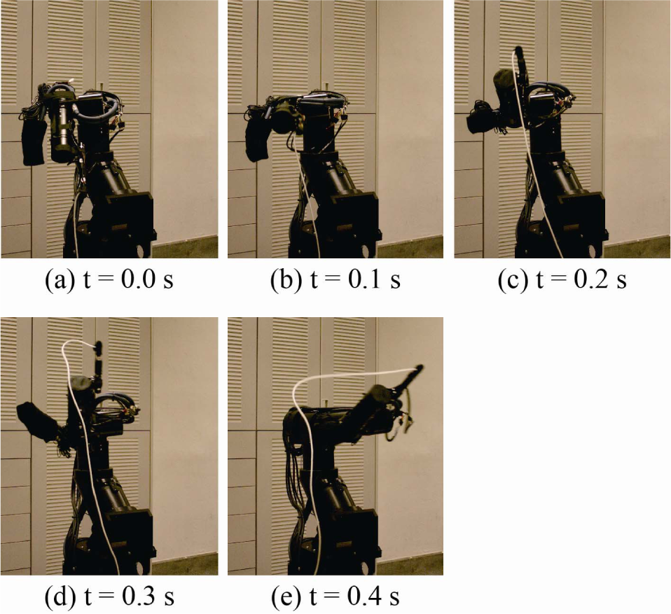
In this section, we explain the analysis of dynamic, high-speed knotting of a flexible rope. First, dynamic, high-speed knotting performed by a human subject is analysed in order to extract the arm motion that achieves this knotting task. Fig. 3 shows a sequence of continuous photographs of dynamic, high-speed knotting performed by the human subject: Fig. 3(a) shows the initial state, Fig. 3(b) shows how the subject moves the rope using shoulder motion, Fig. 3(c) shows loop production using shoulder and elbow motions, Fig. 3(d)–(e) show the rope moving through the loop using the rope's inertia when the rope sections collide and Fig. 3(f) shows the final state where the knotting task is completed. From these images, we can conclude that dynamic, high-speed knotting using deformation of the rope will be achieved by a combination of shoulder motion and elbow motion. Fig. 4 shows an overall image of the dynamic, high-speed knotting and the high-speed arm motion. This knotting task is considered to be one example of dexterous manipulation of a flexible object and since the success rate for human subjects learning how to perform this task is only about 15 %, the task is considered to be extremely difficult.

Strategy of dynamic, high-speed knotting
The most important elements of this task are:
1) forming a loop on the rope
2) causing collision of the rope sections at the intersection of the loop.
Thus, it is important to perform motion planning of the manipulator so as to realize these elements. In this study, the tip trajectory obtained from analysis of the human knotting is not used. Instead, we propose a method in which motion planning of the arm can be obtained from a given rope configuration. This motion planning method can be applied to various tasks involving dynamic manipulation of flexible objects.
4. Modelling and Simulation
In this section, a simple deformation model of a rope will be derived and this will be used to generate a robot trajectory, verify the validity of the robot trajectory, calculate the deformation of the rope and propose a motion planning method.
As can be seen from the dynamic, high-speed knotting performed by the human subject, shown in Fig. 3(a)–(c), the rope section located far from the part grasped by the subject does not move during the high-speed motion. On the other hand, the rope section located near the grasped part deforms so as to track the motion of the subject's arm.
As discussed above, the rope deformation depends on the high-speed robot motion. Therefore, we can assume that the rope deformation can be derived algebraically from the robot motion. The rope deformation model can be described as a relational expression (static model) derived from the robot motion in this study. Also, since the rope deformation can be calculated algebraically from the robot motion, the model of the rope deformation will be simpler than typical models [11], [12], [13].
If the dynamic manipulation is performed in slow motion, gravity acts on the rope. In that case, the algebraic equation does not hold, and we have to consider the typical equation of motion of the rope. As a result, dynamic manipulation in slow motion is extremely difficult. Thus, high-speed robot motion is required in order to achieve dynamic manipulation.
4.1 Kinematics of manipulator
Here we consider the kinematics of the manipulator (Fig. 2) in order to derive the tip position of the manipulator. Since the tip position of the manipulator does not depend on the joint angle of the circulation axis (θ4) of the lower arm, this joint angle can be neglected. The joint angles and the tip position of the manipulator are given by θ ∈ R3 and r ∈ R3, respectively. In general, the relationship between the tip position and the joint angles can be obtained by

Although the details of the derivation are omitted, the tip position is derived by using the Denavit–Hartenberg description.
4.2 Simple deformation model of rope
The typical rope models are frequently described by a distributed parameter system (partial differential equation). In other approaches, the rope models are approximated by a multi-link system and the equation of motion (ordinary differential equation) for each joint is derived. In this research, we apply the multi-link system to the rope model in order to propose a simple deformation model of the rope. Then, the equation of motion can be replaced by an algebraic equation under the constraint of sufficiently high-speed motion of the robot [17], [18].

Concept of simple model
The following assumptions are introduced in the simple deformation model of the rope.
1) The behaviour of the rope section located “near” the part grasped by the manipulator depends on the robot motion.
2) The behaviour of the rope section located “far” from the part grasped by the manipulator does not depend on the robot motion.
3) The distance between any two joint coordinates of the rope is not variable.
4) There is a time delay between the robot motion and the subsequent rope deformation.
5) Twisting of the rope is not taken into account.
The near and far positions mentioned here are roughly defined as follows. Near means that the joint position of the rope is between the part grasped by the manipulator and the midpoint of the rope. On the other hand, far means that the joint position is between the free end of the rope and the midpoint of the rope.
The first assumption means that the rope deformation can be obtained from the tip position of the manipulator and the second assumption means that rope deformation does not occur even if the manipulator moves. The third assumption is the constraint that the link distance in the multi-link model does not change. The fourth assumption means that even if the robot moves, the rope section located far from the grasped position does not deform during the time delay.
From the above conditions, we assume that the rope deformation can be algebraically represented by the following equation:
where i is the joint number of the rope (i = 1, 2, · · ·, N = 20), si ∈ R3 is the i-th joint coordinate of the rope and di is the time delay (di = λl(i – 1) at the i-th joint, where λ (= 1.2) is a normalized time delay and l is the link distance). The first joint is set at the position grasped by the robot. As a result, the time delay d1 is equal to zero. Fig. 5 shows the concept of the proposed simple model. We assume that the rope deforms so as to track the trajectory of the manipulator in the proposed model, as shown in Fig. 5.
Since the proposed model (Eqn. (2)) does not include an inertia term, Coriolis and centrifugal force terms, or a spring term, we do not need to estimate the dynamic model parameters; only the normalized time delay λ has to be estimated. The value of λ may be dependent on the speed of the robot motion and it is easy to estimate the value of λ. The advantage of the proposed model is that the number of model parameters is lower than one of the typical models. Therefore, the proposed model itself is robust. Moreover, since the rope model can be algebraically calculated, the simulation time becomes much shorter. The theoretical derivation of this model (Eqn. (2)) is examined in references [17] and [18].
In Eqn. (2), the effects of gravity are not considered. If we consider gravity, Eqn. (2) is rewritten as

Since the motion time is very short in the proposed strategy, the effects of gravity can be considered to be extremely small. Thus, in this model we approximate the effects of gravity by using the typical term
Furthermore, since the proposed models (Eqns. (2) and (3)) do not include model parameters that describe the characteristics of the rope, we consider that the proposed models can be applied to various ropes.
4.3 Correction of distance between two joint coordinates
When describing the rope deformation using Eqn. (2) or (3), there exists a case where the distance between two joint coordinates cannot be kept constant, as shown in Fig. 6(a). In Fig. 6(a), the dotted line depicts the rope deformation obtained by Eqn. (2) or (3) and the solid line depicts the corrected rope deformation in the method proposed here. In order to satisfy Assumption 3, the joint coordinates of the rope need to be converted as follows:
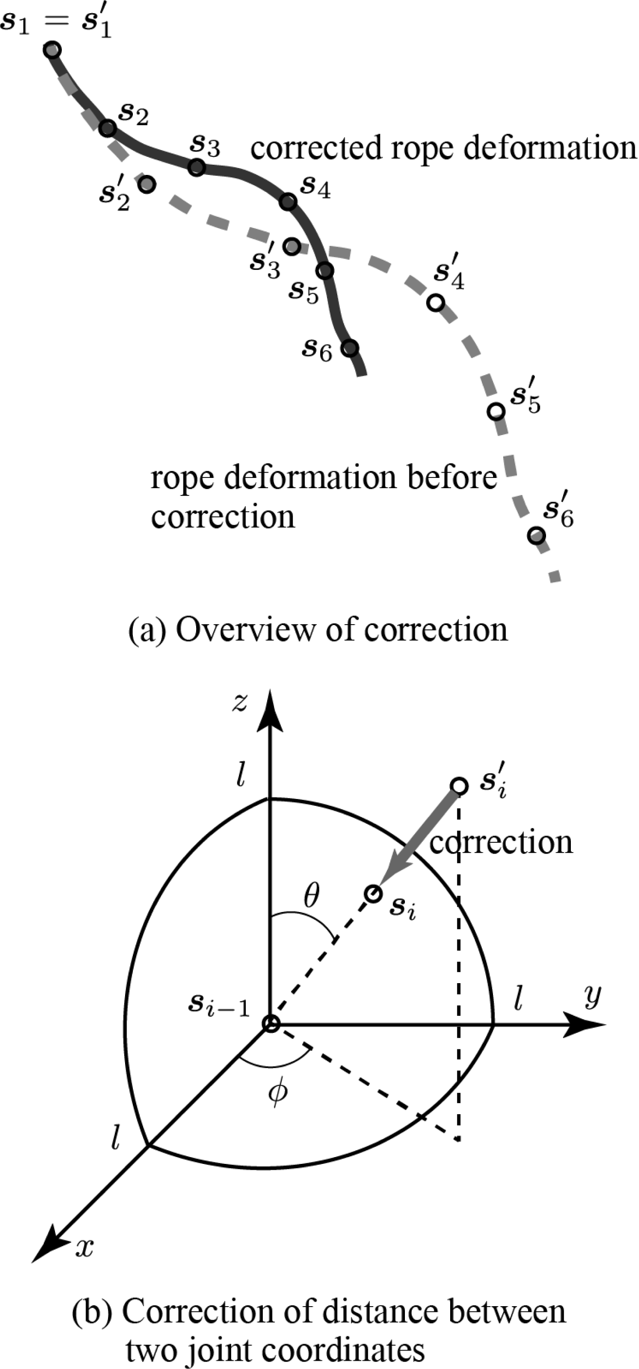
Illustration of correction of distance between two joint coordinates
The i-th joint coordinate to be converted is defined as si = [xi yi zi] and the prior (that is, nearer to the position grasped by the robot) joint coordinate is

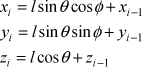
In the case where D is not equal to l (l is the link distance), Assumption 3 is not satisfied. Therefore, the i-th joint coordinate si is corrected in terms of polar coordinates as follows:
where

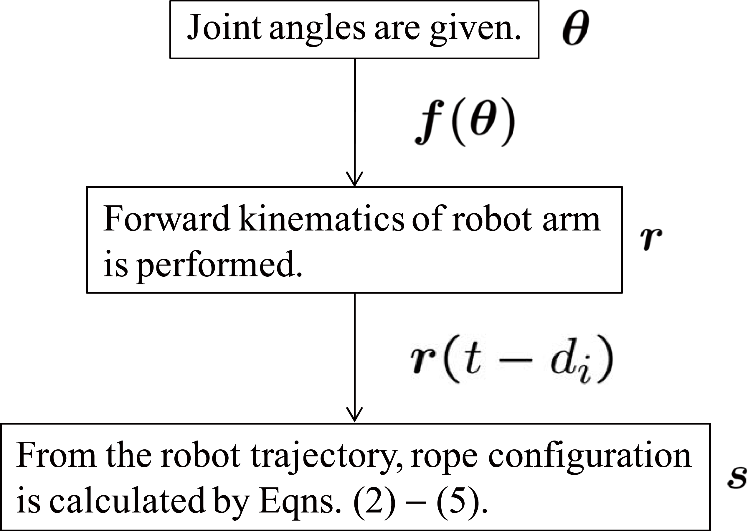
Simulation flow of forward problem
Fig. 6(b) shows an illustration explaining the correction of the distance between two joint coordinates. The centre means the coordinate of the (i-1)-th joint and the coordinate of the i-th joint is corrected. If the position of the i-th joint is not located on a sphere with radius l, the position is corrected as shown in Fig. 6(b). By performing this correction, Assumption 3 can be satisfied and the appropriate rope deformation can be obtained in the simulation, as shown in Fig. 6(a).
Fig. 7 shows the simulation flow of the forward problem. First, the joint angles of the manipulator are given. Then, the tip position of the manipulator is calculated using the forward kinematics. Finally, the rope deformation is derived using Eqns. (2)–(6).
4.4 Validation of proposed model
Simple simulations, such as sinusoidal motion, half-circle motion and rectangle motion, were executed in order to confirm the validity of the proposed model with experimental results. In the simulation and the experiment, the length of the rope was 0.5m. Since the number of joints, N, of the multi-link rope model was set at 20 by trial and error, the link distance, l, was 0.025m. In the experiment, the tip position of the manipulator was made to follow the trajectory for achieving each type of motion (sinusoidal, half-circle and rectangle).

Experimental result of sinusoidal motion

Simulation result of sinusoidal motion
4.4.1 Sinusoidal Motion
In the sinusoidal motion, the amplitude and frequency were 2 deg and 5Hz, respectively. Figs. 8 and 9 show the experimental result and simulation result for the sinusoidal motion of the arm, respectively. As can be seen from these figures, the dynamic behaviours of both results were approximately the same.
4.4.2 Half-circle Motion
Figs. 10 and 11 show the experimental result and simulation result for the half-circle motion, respectively. It can be seen from these figures that the dynamic behaviours of both results were approximately the same. Thus, the validity of the proposed rope deformation model can be quantitatively confirmed from these simulation and experimental results.

Experimental result of half-circle motion

Simulation result of half-circle motion
4.4.3 Rectangle Motion
Figs. 12 and 13 show experimental and simulation results for rectangle motion, respectively. From these figures, we can see that the rope configuration was almost the same. As a result, we confirmed the validity of the proposed model (simple model of rope deformation) and we found that the number of joints (N = 20) was appropriate. However, there was a slight error between the simulation and experimental results. The reason is that the effects of gravity in the proposed model are approximated in the case of high-speed motion. As a result, there is a difference between the actual effects of gravity and the approximated effects.
In addition, we examined other simulations using the Open Dynamics Engine (ODE) and verified the proposed model by comparing the simulation results with the experimental results [17][18].
4.5 Inverse problem (motion planning method)
This section explains the inverse problem of deriving the joint angles of the manipulator from the rope configuration. Fig. 14 shows the flow of the inverse problem.
First, we give the number of links of the multi-link system of the rope. The desired rope configuration (
Experimental result of rectangle motion [18]

Simulation result of rectangle motion
Second, the desired rope configuration (

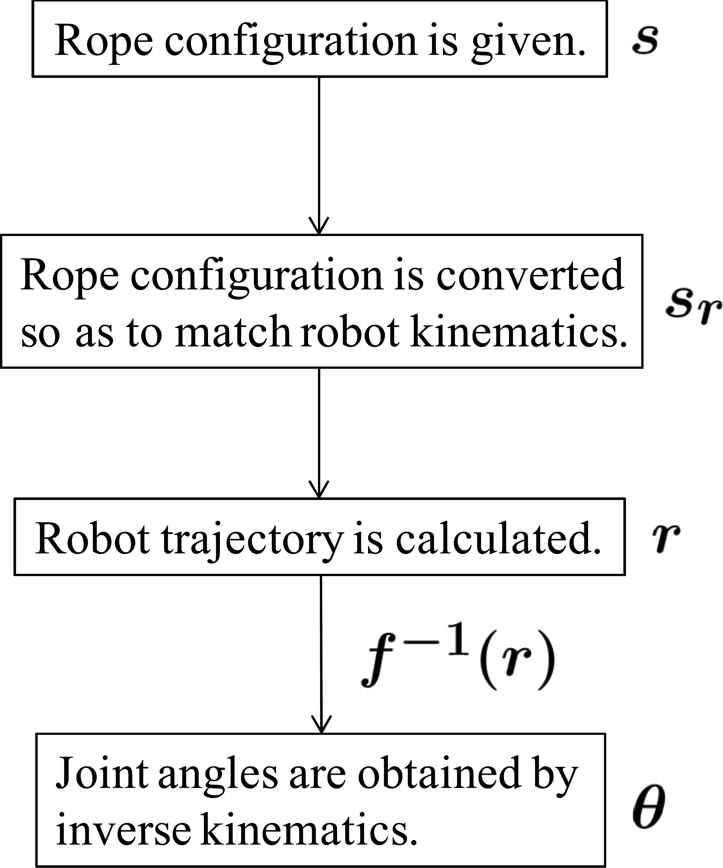
Simulation flow of inverse problem

Compensation for the effects of gravity
where i is the joint number, N is the total number of joints, sr is the converted rope configuration, T is the motion time, g is gravitational acceleration, and the superscript T indicates the transpose. Since the motion time of the robot is very short, the gravity compensation term for each joint of the rope is approximated by
Third, the trajectory of the tip position (r) of the manipulator is calculated from the converted rope configuration (

where N (= 20) is the number of joints and T (= 0.5 s) is the motion time. The trajectory is determined so as to linearly move from the N-th link to the first link during the motion time T. Here, the trajectory is calculated so as to compensate for the effects of gravity (Fig. 15).
Finally, the joint angles (
Rope configuration

Joint trajectory of manipulator
This motion planning method allows the robot trajectory to be obtained by tracking the reference shape of the rope. Thus, if we know the kinematics of the manipulator, the motion planning method can be applied to typical manipulators.
4.6 Simulation of dynamic high-speed knotting
In this section, the simulation results of dynamic, high-speed knotting by the manipulator are shown. The simulation conditions are the same as those used in the above section.
In order to achieve dynamic, high-speed knotting of the rope, motion planning of the manipulator is extremely important. In particular, loop production on the rope and collision of the rope sections at the intersection of the loop are key elements to the success of this task. Thus, motion planning is required so as to perform these elements.
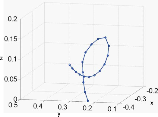
In this simulation, the rope configuration (
From this result, the same configuration as the given rope configuration is obtained as shown in Fig. 18(d). Namely, the joint trajectory obtained by the simulation can be used in the experiment. In addition, it can be confirmed that loop production on the rope and collision of rope sections in the loop are achieved. By using the proposed model, the trajectory of the manipulator can be algebraically obtained when an arbitrary rope configuration is given.

Simulation result of dynamic, high-speed knotting
From this simulation result, we cannot understand whether or not a rope section will pass through the loop after the collision of the rope sections. So, we will analyse this phenomenon using a simple model in the next section.
4.7 Possibility of dynamic high-speed knotting
In this section, we discuss the possibility of dynamic, high-speed knotting. After the collision of the rope sections, one rope section has to pass through the loop of the other rope section, as shown in Fig. 3(d)–(f).

Simple analysis model after rope collision
Here we analyse this possibility by using the simple model described in Fig. 19. In this model, since we consider the local behaviour of the rope, we assume that the behaviour of the rope can be approximated by that of a rigid body. The left illustration in Fig. 19 shows the state during rope collision. Here

Moreover, we should consider the loss of the velocity transmission due to the flexibility of the rope. However, it is extremely difficult to derive the value of this loss and therefore, the loss is set at 0.2 in this study. This value was decided by trial and error and represents a somewhat strict condition. If we can confirm the possibility of realizing the task under this strict condition, we consider that the dynamic, high-speed knotting based on the proposed method is sufficiently feasible. Eqn. (9) can be rewritten as

This value (v2) is the initial condition of the simulation. The right illustration in Fig. 19 depicts the analysis model using a pendulum model. In this model we assume that the mass of the rope is concentrated at the tip. The mass is given by
The parameters used in this analysis were as follows:
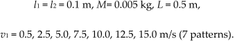
Fig. 20 shows the time-series values of the joint angle in the analysis model and Fig. 21 shows the phase trajectory between the joint angle and the joint's angular velocity under the above conditions. From these results it can be seen that when the velocity v1 is 12.5m/s, the joint angle θ becomes greater than π rad, and the rope twists around the other section of the rope one time. Furthermore, when the velocity v1 is 15.0m/s, the joint angle θ becomes greater than 3π rad, and the rope twists around the other section of the rope two times. As a result, in order to complete dynamic, high-speed knotting, the velocity v1 should be set at over 12.5m/s at the moment the rope sections collide. This velocity can be achieved by the high-speed manipulator used in this study. Thus, dynamic, high-speed knotting can be performed.

Time Series of joint angle θ in analysis model

Phase trajectory between joint angle θ and joint angular velocity θ in analysis model
5. Experimental Results
In this section, we describe the experimental results of dynamic, high-speed knotting of a rope based on the simulation results.
Fig. 22 shows the experimental results of dynamic, high-speed knotting by the high-speed manipulator. In this experiment, the joint trajectories of the manipulator obtained from the simulation results were used and the diameter and the length of the rope were 3mm and 0.5 m, respectively. It can be seen from Fig. 22 that dynamic, high-speed knotting of the flexible rope was achieved. Since the time required to perform knotting was 0.5s, knotting can be carried out at high speed. This video sequence can be viewed on our web site [20]. In the last 1s of this video, the human subject completed the knotting task. However, this was performed merely to make it easier to see the knot and is not essential in this study.

Experimental result of dynamic, high-speed knotting [19]
The success rates for loop production on the rope and for correct collision of the rope sections at the intersection of the loop were about 100% and about 20%, respectively. Consequently, the success rate for dynamic, high-speed knotting of the rope was about 20%. This success rate is higher than that achieved by a skilled human subject for the same task (15%). Since the proposed method is used in the loop production and the success rate for loop production was about 100%, we can confirm the validity of our method. Therefore, the validity of the proposed model and the joint trajectory obtained by simulation can be confirmed. Moreover, it can be considered that motion planning of the manipulator is extremely beneficial in achieving this task.
Possible causes of failure include the collision timing of the rope sections, approximation of the effects of gravity, twisting of the rope and the initial conditions. It should be possible to improve the success rate by introducing high-speed visual feedback. In particular, the success rate of dynamic, high-speed rope knotting will be increased by recognizing the collision timing of the rope sections with a high-speed vision system.
6. Applications of Proposed Method
The proposed method is one strategy for solving the issues faced in the dynamic manipulation of flexible objects and is a practical solution in this field. In addition, we expect that the proposed method will be promising in other studies related to dynamic manipulation of flexible objects. For example, we can envisage the following applications:
Control of a flexible manipulator
Rope shape control (described in Section 4.4)
Ribbon shape control [21]
Dynamic cloth folding by extending the proposed model to a two-dimensional model [22]
A high-performance robot capable of high-speed motion is required in the proposed method. However, since the proposed method does not depend on the characteristics of the robot or the rope, dexterous manipulation of the rope can be executed by appropriately controlling the tip position of the robot. Also, the motion planning method used to obtain the robot trajectory by tracking the reference shape of the rope is a simple technique. Thus, if we know the kinematics of the robot, this motion planning method can be applied to other types of robots.
Moreover, the proposed method is also very effective under gravity-free conditions. We confirmed that the proposed method, with only a constant moving speed of the manipulator, can be applied to the dynamic manipulation of a flexible object under gravity-free conditions [17], [18]. As a result, the high-speed manipulator is not required under gravity-free conditions, and the proposed method can also be applied to low-speed manipulators.
Furthermore, the proposed models (Eqns. (2) and (3)) do not include model parameters that describe the characteristics of the rope. Thus, we can apply the proposed models to various ropes.
7. Conclusions
The aim of this research is to achieve dynamic manipulation of a flexible object. As one example, dynamic, high-speed knotting of a flexible rope by a high-speed manipulator is considered. Typically, in dynamic manipulation of a flexible object, the deformation of the flexible object during the manipulation complicates the modelling and control.
In this paper, the dynamic model of the flexible rope can be reduced to the choice of a simple algebraic model, taking advantage of simplified assumptions that result from the high-speed motion of the robot. Based on this consideration, we proposed a simple algebraic rope deformation model that is calculated from the robot motion. The validity of the proposed model was confirmed with various simulations. Motion planning of the manipulator was achieved by using the proposed model when an arbitrary rope configuration was given. Finally, the experimental results of dynamic, high-speed knotting of a flexible rope were shown.
In future work, we plan to introduce a high-speed visual feedback system in order to improve the success rate of the knotting task. In addition, we will demonstrate other applications involving various ropes by using the proposed method.