
Abstract
Beam-type substrate transport robots are widely used to handle substrates, especially in the solar cell manufacturing process. To reduce the takt time and increase productivity, accurate position control becomes increasingly important as the size of the substrate increases. However, the vibration caused by the flexible forks in beam-type robots interferes with accurate positioning, which results in long takt times in the manufacturing process. To minimize the vibration and transport substrates on the fork as fast as possible, the trajectories should be prevented from exciting the flexible modes of the forks. For this purpose, a fifth-order polynomial trajectory generator and input shaping were incorporated into the controller of the beam-type robot in this study. The flexible modes of the forks were identified by measuring the frequency response function (FRF), and the input shaping was designed so as not to excite the flexible modes. The controller was implemented by using MATLAB/xPC Target. In this paper, the design procedure of input shaping and its effectiveness for vibration attenuation in both “no load” and “load” cases is presented.
1. Introduction
Owing to the development of innovative technologies, the market for solar energy and other renewable energies is growing rapidly. Solar cells are classified into bulk-type cells that use silicon wafers and thin film-type cells that use glass, metal or plastic. Of these, thin film-type solar cells have the potential merits of lower cost and ease of fabricating larger substrates. For these reasons, equipment and robots for manufacturing thin film-type solar cells are being actively developed. To increase productivity, the automation line is composed of various types of robots that handle solar cell substrates, including cassette-transfer, beam-type glass handling, link-type glass handling and vacuum robots [1]. The focus of this paper is on beam-type solar cell substrate transport robots. Beam-type robots use flexible forks to transport the substrate; the residual vibration at the fork end, however, is an obstacle to reducing the takt time. When the substrate is small, the residual vibration caused by the flexible mode is insufficiently large to require delays between transporting processes. However, as the substrate increases in size, the vibration becomes non-negligible. Hwang et al. [2] proposed error compensation methods for the static deflection caused by the flexibility of the arm and fork in liquid crystal display (LCD) transfer robots (LTRs). Seo et al. [3-5] presented analysis and simulation methods for LTRs to predict their flexible mode dynamics. However, methods to reduce the residual vibration of beam-type robots have not been adequately studied from the point of view of their trajectory. Higher-order polynomial trajectories are normally used to prevent the excitation of the flexible mode in the system. If the flexible mode vibration remains marked, an additional trajectory reshaping method - such as input shaping - should be applied to the output of the trajectory generator [6-10]. In this paper, the controller design procedure for a beam-type robot and experimental measurements of the residual vibration at the fork end are presented. After evaluating the baseline vibration, input shaping is designed so as not to excite the flexible mode vibration and its effectiveness is assessed.
2. Configuration of the Beam-Type Robot
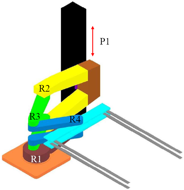
A three-dimensional (3D) model of a beam-type robot is shown in Figure 1. It has 5-degrees of freedom (DOFs) for four revolute joints (R1, R2, R3, R4) and one prismatic joint (P1). The robot has two forks in the upper and lower arm, which can transport two solar cell substrate pieces (1100 mm × 1400 mm × 4 mm, 15.2 kg). One arm has three revolute joints (R2, R3, R4), and both arms are connected to the prismatic joint link (P1). The P1 joint moves the arm upwards and downwards on the post by a ball screw mechanism. The R1 joint rotates the post on the base, whereas the R2, R3, and R4 joints extend and fold the forks.

Three-dimensional model of beam-type robot
3. Controller Design
3.1 Dynamic Modelling
The derivation of a dynamic model is a prerequisite for controller design and motion simulation. However, deriving the dynamic model analytically for a 5-DOF robot is difficult. One way to avoid this difficulty is to convert the 3D computer-aided design (CAD) model into a MATLAB/SimMechanics block diagram by using SimMechanics Link [11-13]. The converted dynamic model can be included in a MATLAB/Simulink control block, and dynamic simulations can be easily performed. Moreover, the robot motion that corresponds to the simulated results can be visualized; this allows the designer to observe and easily understand the robot's motion. A simplified 3D model of a beam-type robot for constructing a dynamic model is shown in Figure 2. The dynamic model for motion simulation, converted from this 3D CAD model by SimMechanics, is shown in Figure 3.
Simplified model of beam-type robot for constructing the dynamic model

SimMechanics block diagram for the beam-type robot
3.2 Controller Structure and Trajectory Generator
Figure 4 shows the trajectory generator and controller structure for each joint. The target positions are first delivered to the trajectory generators, which then generate the reference position, velocity and acceleration trajectories. The acceleration, deceleration and maximum velocity are determined based upon the takt time specifications. The trajectories are generated by using the fifth-order polynomial for a smooth motion that can minimize the vibration [14]. The each joint controller has a dual-loop structure that consists of an inner velocity controller and an outer position controller. The method of control used is the anti-windup proportional-integral-derivative (PID) control. Velocity commands are calculated by adding the results of the position controllers and the velocity feedforward terms based upon the reference position trajectories, and then sent to the velocity controllers as velocity inputs. In the same manner, torque commands are calculated by adding the results of the velocity controllers and the acceleration feedforward terms from the trajectory generator, which are then sent to the current drivers. The sampling frequency was 1 kHz and the initial PID gains for each joint were selected as having bandwidths of 2 and 20 Hz for each position and velocity controller. In addition, the gains were tuned using the Simulink optimization blockset.

Trajectory generator and controller structure for each joint
3.3 Motion Simulation
Figure 5 shows the Simulink model for the overall simulation. To evaluate the designed controllers, simulation of the takt time-based motion trajectories was performed. Table 1 shows the reference positions of each axis for one transport cycle in the manufacturing process, and Figure 6 shows the simulated results for the full trajectories corresponding to those in Table 1. The blue lines are the reference position trajectories, and the red lines are the tracking positions. It can be seen that they precisely overlap. This means that the designed controller can achieve satisfactory tracking performance.
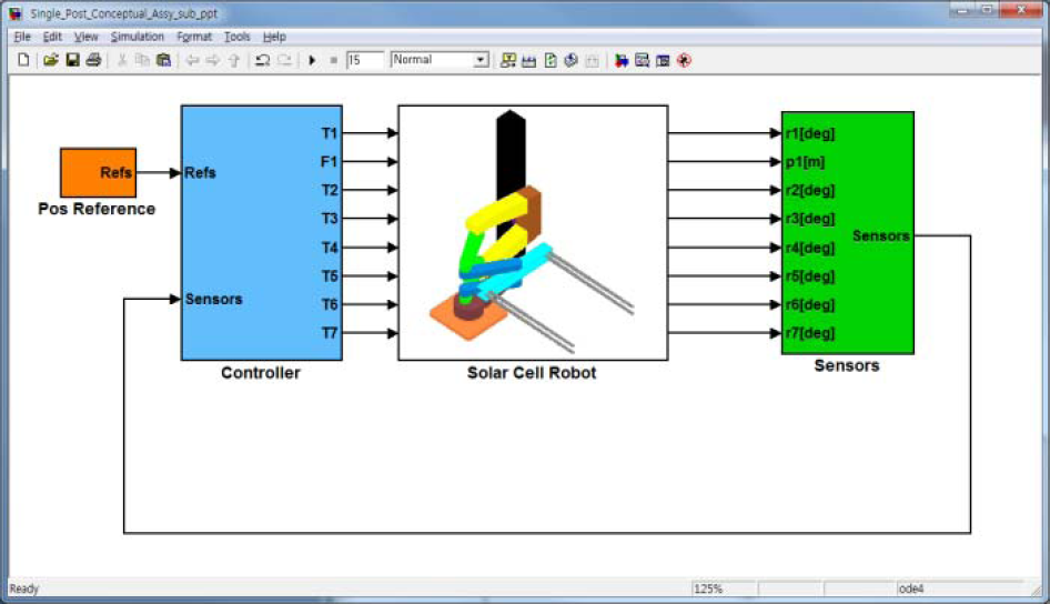
Simulink block diagram for motion simulation

Results of simulating full motion trajectories for one transport cycle
Reference positions of each axis corresponding to one transport cycle

4. Measurement of the Baseline Vibration
If the settling time of the fork vibration after one motion is long, the robot should wait for the residual vibration to decay before beginning another motion. This may result in a longer takt time. The vibration of the fork - due to its flexible mode - is mainly excited by P1 joint motion, which causes vertical acceleration and jerk. Therefore, the magnitude and settling time of the vertical vibration at the ends of the forks are the important indices indicating the vibration control performance of the trajectory generator and controller. In this section, the experimental measurements of the vertical vibration at the end of the fork after P1 axis motion are presented.
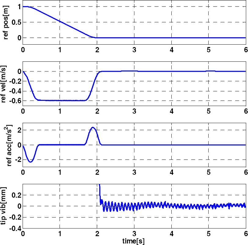
Figure 7 shows the experimental setup for measuring the vertical vibration at the fork end after P1 axis motion. The motion controller is implemented using MATLAB/xPC Target running on an industrial computer. The control program is written in the form of a block diagram in MATLAB/Simulink, which is almost the same as that in Figure 5 except for the hardware interface block. The motion controller gives torque commands to the current drivers for each axis to move the axis to the reference positions. Because it is important to measure the vertical displacement of the fork end caused by the flexible mode, the laser displacement sensor rather than the accelerometers is used in this study to measure the vibration. The laser displacement sensor with the specifications in Table 2 is located at the fork end. Figure 8 shows the reference position, velocity and acceleration profile for a 1-m downward motion in the P1 axis and the vertical vibration at the fork end right after the motion. The dominant frequency component of the vertical vibration was 11.4 Hz and the maximum peak-to-peak magnitude was 0.47 mm. The main source of the 11.4 Hz vibration is the flexible mode of the fork. Therefore, another method, such as input shaping, was required so as not to excite the flexible mode vibration.
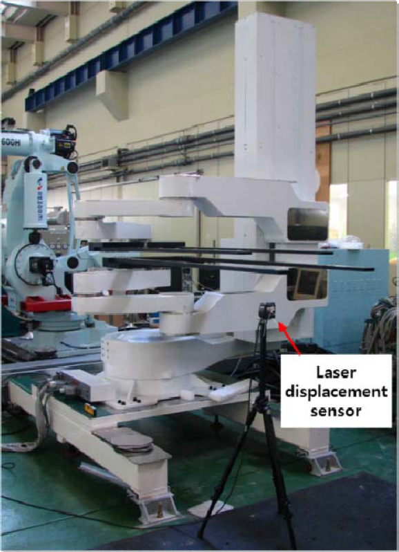
Experimental setup to measure the fork end vibration after P1 axis motion

Reference position, velocity, and acceleration profile for P1 axis motion and the vertical vibration at the fork end
Specifications of the laser displacement sensor

5. Input Shaping
5.1 Basic Concept
Input shaping is a well-known feedforward control technique for reducing vibrations in flexible systems. It is implemented by convolving a sequence of impulses with any desired command, and the amplitudes and temporal locations of the impulses are obtained from the natural frequencies and damping ratios of the system [6-10]. There are several kinds of input shaping method, such as the zero vibration (ZV), ZV and derivative (ZVD), and ZV and double derivative (ZVDD) methods. In practice, ZVD input shaping is popular because it is robust to errors in the values of the natural frequency and damping.
In this study, the vibration attenuation of the flexible fork was evaluated after implementing ZVD input shaping. As shown in Figure 4, because the velocity/acceleration trajectories and position trajectory are fed forward to the controller, input shaping should be applied to all three trajectories to generate the reshaped position, velocity and acceleration reference trajectories, as shown in Figure 9.

Block diagram for ZVD input shaping considering velocity and acceleration feedforward terms
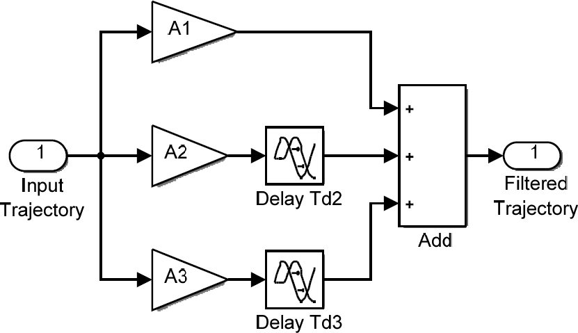
The design procedure for ZVD input shaping has been described in detail elsewhere [9-10]. The flexible system in this study is assumed to be a second-order system with the transfer function:

where ωn is the natural frequency and ζ is the damping ratio. The input and output of P(s) are the vertical motion of the P1 axis and the vertical displacement of the fork end, respectively. A1, A2, A3, Td2 and Td3 in Figure 9 are given in (2–6):


where
5.2 Identification of the Flexible Mode
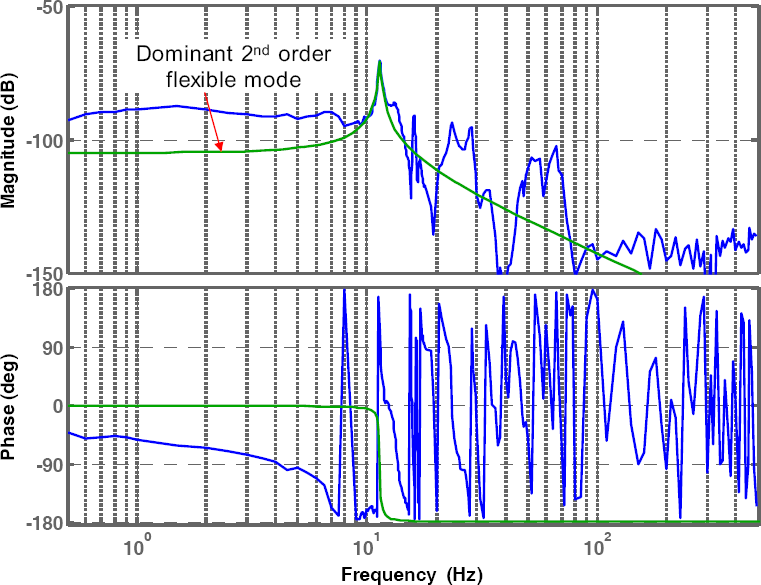
As shown in (1–6), the natural frequency and damping ratio of the flexible mode should be identified first to design the input shaping for the forks. Given that one end of each fork is horizontally attached to an arm, the flexible modes of the forks are mainly subject to P1 axis motion. To obtain the P1 axis frequency response function (FRF) of the forks, a swept-sine input ranging from 0–500 Hz was added to the control input for the P1 axis and the vertical displacement of the fork end was measured with the laser displacement sensor. Meanwhile, the data acquisition (DAQ) system recorded the vertical displacement of the stem of the arm by using the P1 axis feedback encoder at the same time. Figure 10 shows the measured FRF. The blue line represents the nominal rigid body plant for the P1 axis and the green line indicates the FRF measured using the P1 axis encoder. Observing the flexible mode in the green line is difficult because there are few flexible components in the stem of the arm. The red line represents the FRF measured by the laser displacement sensor. It shows several flexible modes that result from the flexibility of the arm joints, arm structures and fork beam.
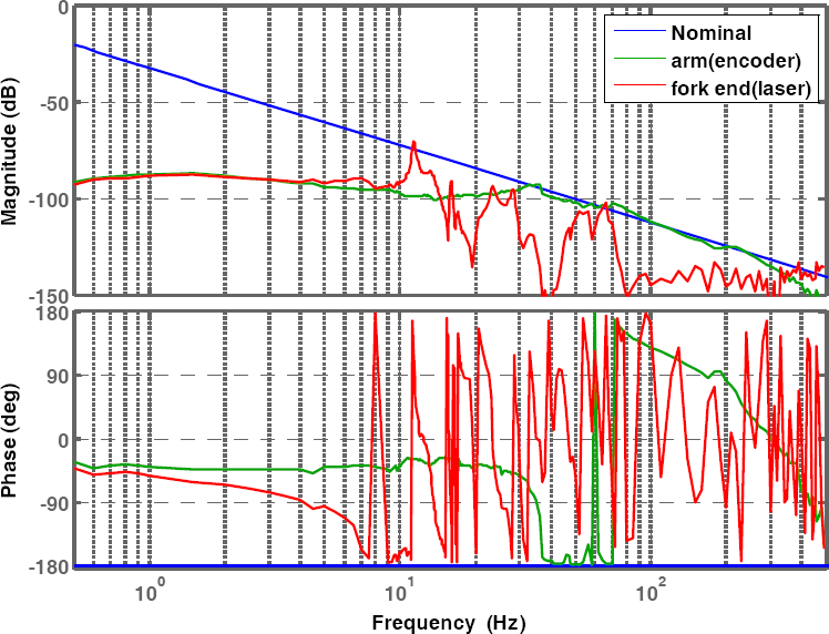
Frequency response functions of a nominal rigid body model (blue line), a measured rigid body only (green line) and the measured flexible mode (red line) for the P1 axis
The dominant flexible mode frequency in the FRF measured by the laser displacement sensor is 11.4 Hz. This vibration is caused by the flexibility of the fork beam; its frequency is identical to the dominant frequency component of the residual vibration in Figure 8. Therefore, the main residual vibration frequency can be considered as the first bending mode frequency of the forks. Figure 11 shows the reconstructed FRF for the first bending mode of the fork beam only with a damping ratio 0.01. The ZVD input shaping for a given natural frequency and damping ratio was designed and implemented based upon the block diagram in Figure 9. Figure 12 describes a MATLAB/Simulink block diagram model for the implementation of input shaping.
Measured flexible mode (blue line) and reconstructed flexible mode for the fork only in the P1 axis
Simulink block diagram for input shaping
6. Experimental Results with Input Shaping
6.1 Residual Vibration for the “No Load” Case with Input Shaping
After implementing input shaping, the vertical vibration at the fork end was measured with the same experimental setup and procedure. Figure 13 shows the reference position, velocity and acceleration profile and the vertical vibration at the fork end immediately after the motion with input shaping. Although the overall duration of the trajectories increased by 0.0877 s based upon (6), the maximum peak-to-peak magnitude of the 11.4-Hz vertical vibration component decreased to 0.19 mm. The results show that the designed input shaping could effectively attenuate the flexible mode vibration of the fork in the beam-type robot.
Reference position, velocity and acceleration profile for the P1 axis motion and vertical vibration at the fork end in the case of “with input shaping”
6.2 Residual Vibration for the “Load” Case with Input Shaping
In the manufacturing process, the solar cell substrates are placed on the forks and transported to other processes. Therefore, evaluating the vibration attenuation of input shaping for the “load” case is important. In this experiment, the substrates (1100 mm × 1400 mm × 4 mm, 15.2 kg) were loaded on the fork and vertically transported. First, the residual vibration for the case “without input shaping” was measured by the laser displacement sensor (Figure 14 (a)). The natural frequency of the fork with load is completely changed from the 11.4 Hz of the “no load” case to 5 Hz. Moreover, the maximum peak-to-peak magnitude of the residual vibration increased to 13.5 mm and the maximum acceleration was 3.45 m/s2. This amount of vibration would result in a delay between the processes and increase the takt time. So as not to excite this vibration, the input shaping for the “load” case was designed and implemented. In this case, ωn was 5 Hz and ζ was 0.01. Figure 14 (b) shows the residual vibration for the case “with input shaping.” Although there is a load on the fork, the maximum peak-to-peak magnitude of the vibration was 0.8 mm and the maximum acceleration was 0.65 m/s2, which was significantly less than in the case “without input shaping.” These experimental results confirmed that the residual vibration due to the flexible mode of the fork in the beam-type robot could be effectively minimized using input shaping.

Residual vibration for the “load case” (a) without input shaping and (b) with input shaping
7. Conclusion
In this paper, the controller design procedure for a beam-type substrate transport robot was presented. The initial gains for the dual-loop feedback controllers were selected to control the dynamic model composed of MATLAB/SimMechanics blocks. The reference position trajectories and the trajectories of the velocity/acceleration feedforward terms were generated based on a fifth-order polynomial. After implementing the initial controller and the trajectory generator, the residual vibrations at the fork end of the beam-type robot were measured for the “no load” case. That the dominant vibration is caused by the fork flexibility was verified by measuring the FRF of the fork. Based upon the measured flexible mode, the input shaping was designed so as not to excite this vibration. This reduced the residual vibration by 50%. When input shaping was applied to the “load” case, in which the flexible mode natural frequency was greatly reduced from that of the “no load” case, the vibration attenuation was more marked and the maximum peak-to-peak magnitude of the residual vibration decreased from 13.5 to 0.8 mm. Input shaping in “load” case reduced the residual vibration by 94%. These results suggest that if input shaping is applied to beam-type robots that transport larger substrates, the increase in takt time due to residual vibration can be avoided.