
Abstract
An innovative design of a polyurethane microgripper system with force sensor is developed for the measurement of gripping force in vision-based control. A microgripper mechanism integrated with a force sensing arm is fabricated by an excimer laser. The microgripper is actuated by a self-biased-SMA (Shape Memory Alloy) actuator. A computer-vision method through the ERES (Extended Regional Edge Statistics) algorithm is employed to track the motion of gripper. The position information of the gripping point together with the deflection of the force sensing arm is utilized for sensing force. A fuzzy expert with a PI controller in a visual servo is employed to test the performance of sensing the gripping force in grasping of 38μm diameter metal rod. In the performance test, the microgripper system provides a maximum gripping size of 40μm, a maximum force resolution of 1μN and a maximum gripping force of 58μN.
1. Introduction
Miniaturization of gripper systems for handling small objects has become a challenging area of technology in micro robotic and biomedical industries. In the past, considerable attention has been given to the design and fabrication of microgrippers for micro manipulation during experimental tests, material tests, fabrication processes, assembling operations and maintenance work [1–5]. Since the manipulation of micro objects smaller than 100μm is usually undertaken under a microscope [6], vision-based sensing is essential to ensure successful micro operation. Along with the visual servoing technique developed in robotic manipulations [7, 8], the research trend for microgrippers has evolved toward a micromechatronics system by including force sensing and servo control [3, 5, 9–11].
In the development of microgrippers, various types of microgrippers have been implemented and published in literature since the early 1990s. In the recent years, due to the advantages of material compatibility, production cost and the mechanical properties of applications, the progress of polymer microgrippers has gained notice [12–28]. In a literature survey, the fabrication material for polymer microgrippers was found to mainly include SU-8 [13, 16–18, 22–25] and Polyurethane (PU) [14, 19–21, 26–28]. The actuators employed include laser-powered [12], pneumatic [13], piezoelectric [14, 19, 23, 26], SMA [16, 20–21, 27–28] and thermal-heating [17–18, 22, 24–25] drive actuators.
Information on gripping force is important in micro manipulation in spite of certain applications utilizing only displacement information [1–3]. Force sensing is employed in microassembly processes to protect both microparts and microgrippers from excessive damage forces. Micro force sensing is also essential for the secure manipulation of biological objects. Measurement of both gripping force and displacement can be utilized to obtain the mechanical properties of grasping an object. The micro gripping force depends on the contact material, contact surfaces, scale and operational conditions of the procedure. It is very difficult to make accurate predictions by employing an analytical or experimental model. Online measurement by a computer is essential for obtaining accurate information on the gripping force. In online measurement of gripping force, several studies have been undertaken on silicon and metal-based microgrippers by utilizing integrated sensing or assembled sensing methods [3, 9]. With a microscopic computer-vision system, the vision-based position sensing technique also can be applied to measure grasping force. A vision-based force sensing method, compared with integrated-type and assembled-type sensing methods [3, 9, 29], can be easily implemented and reliably employed to obtain force information. The vision-based sensing method has attracted researchers in developing different sensing mechanisms, computer-vision systems and image processing algorithms for the measurement of micro Newton force [29–31]. Wang et al. [29] employed a finite element model (FEM) with the visual displacement of grid points on a deformed object to estimate the applied force. Greminger and Nelson [30] demonstrated a method using object contour images with a deformable template to estimate the force distribution on a deformed object. Anis et al. [31] proposed a FEM with cross-correlation matching or Gaussian edge detection methods in image processing to estimate the force on a deformed object. Recently, several pieces of research have focused on developing polymer microgrippers with integrated-type [27–28] and assembled-type force sensors [21]. For the proposed vision-based sensing designs, each design has its own advantages and disadvantages. Justification of the performance of each design is related to its application.
In considering the miniaturization of an actuator, the Shape memory alloy (SMA) actuator is relatively small compared with other actuators under the same drive energy and output stroke [32]. There were several different designs of SMA-actuating microgripper developed for micro manipulation. Chang et al. [20] developed a PU microgripper actuated by an arc-shape SMA-wire actuator. The actuator has residual stress from bending the wire to act as a bias spring. Lee et al. [33] developed a silicon microgripper actuated by a bimorphthin-film SMA. The actuator has a layer of SMA film to act as a bias spring. Bellouard et al. [34–35] developed two types of monolithic SMA plate grippers. One type uses a two-way SMA effect and another is integrated with a bias spring. Just et al. [36] developed a monolithic SMA gripper with integrated antagonism. Bütefisch et al. [37] developed a silicon gripper actuated by a differential-type SMA plate. Zhang et al. [38–39] developed a monolithic SMA gripper integrated with a bias spring. Kohl et al. [40] developed a monolithic SMA gripper integrated with an antagonistic SMA pair. Roch et al. [16] developed a SU-8 gripper actuated by a U-shape two-way SMA film. Houston et al. [21] developed a PU microgripper actuated only by utilizing an SMA wire. Kyung et al. [41] developed a stainless flexible-hinge microgripper actuated by an SMA wire and with a flexible hinge as the bias spring. In considering the requirements of miniaturization, a self-biased SMA actuator which does not use an additional bias spring or antagonism is most applicable [33]. Although several SMA-actuating microgrippers have been developed, very little research has been undertaken on utilizing self-biased-SMA (SB-SMA) actuators [20, 27–28].
In this paper, a polymer microgripper with force sensing was developed and tested in a visual servo. Firstly, an SB-SMA actuator was fabricated and the actuated motion was characterized. Next, a force sensing mechanism, by utilizing a compliant-joint PU arm, was analysed, designed, fabricated and calibrated. The same design of a force sensing arm integrated with a microgripper mechanism was fabricated and assembled with the SB-SMA actuator for gripping operations. For obtaining a gripping force in grasping, an experimental setup was installed and a visual tracking algorithm was employed for estimating the deflection angle. Then, the gripping force in grasping a copper rod in vision-based control was measured and analysed. Finally, the present research on developing a polymer microgripper system was concluded.
2. Self-biased-SMA (SB-SMA) actuator
2.1 Fabrication and operation of the microactuator
An SMA actuator for a fast two-way operation usually requires a bias spring to overcome martensite twinning for the recovery of the initial shape. A SB-SMA actuator that integrates both the effects of the SMA and the bias spring is most attractive in the miniaturization of the SMA actuator. A SB-SMA actuator is implemented by including the effect of the bias spring in the fabrication of the SMA micro actuator through introducing residual stress in the SMA material.
A SB-SMA actuator has been developed and employed for actuating microgrippers in gripping and assembly applications [20]. For the SB-SMA actuator employed, the actuator was manufactured mainly by the following procedure. At first, a proper size of TiNi-SMA wire with a specified transformation temperature was obtained and prepared. A roll of TiNi-SMA wire 38μm in diameter was obtained from Dynalloy, Inc. The austenite starting temperature As was 70°C. Secondly, the SMA wire was cut off to provide a 2mm working length plus a margin length on two ends for wire bonding, as illustrated in Figure 1(a). The bonding of the SMA actuator with copper wire was realized by using silver glue. The next step was fixing two ends of SMA wire on two frames using adhesive glue. Two 200μm thick nonconductive glass plates were used for the frame. After the glue hardened, the SMA wire was bent to introduce pre-strain in the wire. The final step was to glue the two frames of bent wire together, as shown in Figure 1(b).

Arc-shape SB-SMA actuator
The operation principle of the SB-SMA actuator is described by the following physical interpretation. For the SB-SMA actuator, the maximum tensile stress is distributed along the outer layer and the minimum tensile stress is distributed in the centre arc of the SMA wire. Therefore, the pre-strain SB-SMA can be modelled as a parallel combination of the outer SMA tube and the inner SMA wire. The outer tube plays the role of the bias spring to store and release potential energy for the two-way operations during the heating and cooling processes. The inner wire is under stress and thermal loading plays the role of shape memory to recover its shape upon heating above the As. With the symmetric arc-shape SB-SMA actuator in operation, the tip displacement in the lateral direction can be cancelled out and only the tip displacement in the axial direction contributes to linear motion.
2.2 Tip position measurement
The tip position of the SB-SMA actuator was measured by utilizing a microscopic computer-vision system. The fabricated SB-SMA actuator was mounted on a multidegrees-of-freedom working station. The resolution of the image system was adjusted and calibrated to give 2μm/pixel. To drive the SB-SMA actuator, an actuating system included Data Acquision card, Advantech PCI-1710HG and drive circuit were used. In experimental testing, the SB-SMA actuator operated safely with an input current of up to 0.1A. The 0.1A input current was considered as the maximum input current for the SMA actuator. The drive circuit was a voltage current converter designed to provide a maximum current of 0.1A. The circuit provided a constant current when it was loaded with the varying resistance of the SB-SMA actuator during heating or cooling operations.
For the measurement of the tip motion of the arc-shape SB-SMA actuator, a visual-based displacement measurement algorithm was developed. At first, an image of the tip motion of the SB-SMA actuator was captured by the image system. The image had a focus plane on the true arc of tip displacement. The size of the image was 640×480 pixels. Secondly, the captured image was processed by employing a binary operation to enhance the tip edge of the arc in the image. Next, a scanning line was constructed and utilized to find the tip position of the SB-SMA actuator, as shown in Figure 2.
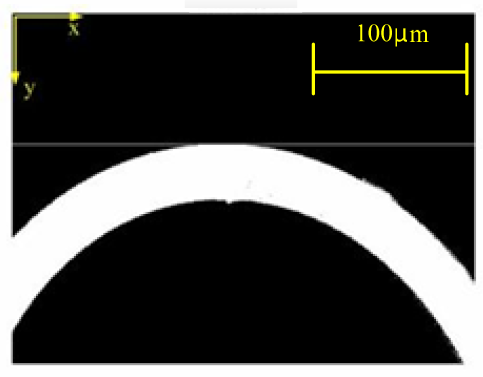
Scanning line for finding tip position after binary operation
A correlation method was proposed to find the tip position of the SB-SMA actuator. The correlation method was implemented firstly by finding the correlation between the grey level of a horizontal scanning line along the y-axis and that of the ith-row image on the y-axis. The ith correlation is given as
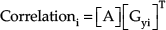
where [A]=[1 1 1 … 1]1×640 is the grey level distribution of the scanning line and [Gyi] is a grey level distribution of the ith-row image on the y-axis. By utilizing (1), the ith correlation is calculated when the scanning line is at the ith-row image on the y-axis. When the ith correlation starts to give a non-zero value, the scanning line just touches the tip of the image. The correlation for different y-positions of the scanning line was obtained as shown in Figure 3.
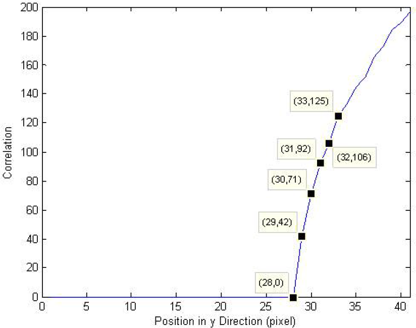
Measurement of tip position by correlation
From Figure 3, it was observed that the tip position was near 28 pixels on the y-axis. With the image calibration and correlation method for tip position measurement, the tip displacement was obtained by measuring the instant tip position and subtracting the initial tip position. By employing a measurement approach, the fabricated SB-SMA actuator was tested to provide an approximately 10μm stroke with an input of 100mA on 3V. The heating and cooling of the SB-SMA actuator was undertaken by utilizing electrical resistance and still air, respectively. The still air was maintained at 26-27°C.
2.3 Open-loop dynamic response
In motion control, the SMA micro actuator is usually operated in the incomplete transformation during the heating and cooling processes. To investigate the open-loop behaviour of the SB-SMA actuator, an amplitude-decaying sinusoidal voltage was employed as the command signal. The output displacement of the actuator was measured by the correlation approach. The response of current, resistance and displacement were recorded, as shown in Figure 4.
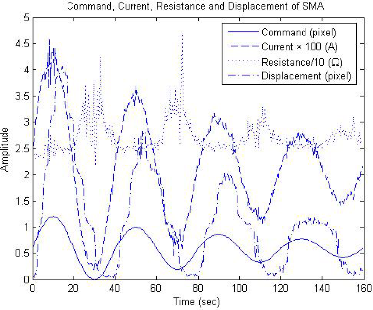
Open-loop test with amplitude-decaying sinusoidal command
From the recorded results, it was observed that the current response followed the input command. Both the resistance response and displacement response were far from the decaying-sinusoidal wave. It was also noted that when the SB-SMA actuator was operated to reverse the motion direction, the resistance response was highly fluctuated. The highly fluctuated phenomenon may due to the effects of phase transformation in the SMA microstructure. To obtain a clear relationship between current and displacement, the fluctuating response data needs further processing. Considering that the signal response of the SB-SMA actuator was highly unsteady; an effective method of wavelet decomposition was utilized to extract the low-frequency content of the unsteady signal. Figure 5 shows that a clear relationship between current and displacement was obtained by employing the Wavelet transform with db10 level 5. In data processing, level 5 was high enough for obtaining smooth data. From Figure 5, it can be noted that the initial transient data were ignored in performing the Wavelet method. It can also be observed that except the first loop, all the others converge together to zero displacement with an input current of up to 25mA. This phenomenon may be due to the thermal effect on tuning the internal crystal pre-strain after the first heating cycle. The SB-SMA wire played the same role as an additive bias spring in pulling back the SMA actuator while it was cooling down [42]. However, the self-biased spring was more time-varying in different cycles when the SMA actuator was pulled back by reducing the input current.

Input current and output displacement from open-loop test
3. Microgripper with vision-based force sensor
3.1 Design and fabrication of force sensing mechanism
In designing a force sensor, a force sensing mechanism is desired to give linear elastic deformation under an applied load. For a vision-based micro force sensor, the deformation of the mechanism creates deformed data in the image and then the image is processed, calibrated and used to measure force. For the measurement of micro Newton force, a simple cantilever arm was selected as the force sensing mechanism. In order to increase the sensitivity of the deflection to the micro loading force, a cantilever arm with a compliant joint, instead of a uniform beam, as shown in Figure 6, was selected.

Force sensing arm with compliant right circular joint
The micro force sensing arm with a compliant joint was designed to give a linear relationship between the applied force and deflection. In the preliminary design, the deflection of a compliant joint under loading was analysed by employing the formula by Paros [43]. For a right circular joint with r/t ≧ 2, the relationship between the moment and the deflection angle about the z-axis is given by

where E is a Young's modulus, Mz is a moment about z-axis and α z is an angular deflection about z-axis. From (2), the error sensitivities of Mz to t and Mz to r are obtained, respectively, as given by (3) and (4)


The results of (3) and (4) reveal that the error sensitivity of moment error due to the error in t is higher than that due to the error in r in the fabrication of the force sensing arm. From (2), the sensitivity of the deflection angle to the moment is proportional to t−5/2. Therefore, a small and accurate t in the fabrication of force sensing arm is desired for accurate and sensitive sensing of micro-scale force. Considering that a micro compliant joint is operated repeatedly in measuring gripping force; a fatigue sustained elastic polymer is employed. In the proposed design, an elastomer was selected for the fabrication of the sensing arm by utilizing PU film. For accurate fabrication of the sensing arm, a micro fabrication method by an excimer laser was selected. By utilizing Exitech 2000 with mask projection, accurate geometrical dimensions were fabricated [27]. Through 10x size reduction by an optical lens, the accurately fabricated minimum dimension was 10μm. By assigning t = 10μm, r was selected as twice t to give 20μm. For the sensing arm to be operated in a linear range, the maximum deflection angle was limited to 10°. The deflection of the sensing arm was negligible under the loading of self-weight. For the PU film, the thickness = 80μm, the averaging Young's modulus [44] = 76.4 MPa, Poisson's ratio = 0.25 and the density = 46kg/m3. The length of the sensing arm from the y-axis, referring to Figure 6, to a loading point was 225μm. The maximum applied load for α z = 10° was calculated to give 23.75μN. Using the preliminary design and (2), a detailed analysis and design of the sensing arm was obtained by employing ANSYS with a Plane183 element. From the geometrical design of the sensing arm, a mask of ten times the scale of the geometrical dimensions was etched and employed for the fabrication of the sensing arm. By utilizing Exitech 2000 in fabricating a prototype, the dimensions of the fabricated sensing arm on two sides were different. The average dimensions were measured to give t = 12.5μm and r = 18.5μm and the length of the loading point to the reference coordinate of the y-axis was measured to give 224.6μm.
3.2 Resolution in force sensing
Since the deflection angle was measured from the image captured by a CCD system, the resolution of the sensing force was limited by the resolution of the CCD system. However, the resolution was easily adjusted with a CCD system for the sensing force. The CCD system employed was calibrated to give a resolution of 0.86μm/pixel. With one pixel resolution in an image, the maximum resolution of displacement was 0.86μm. From the fabricated geometrical dimensions and with the material properties of PU, the resolution of the force sensor was analysed by utilizing ANSYS. With −0.8 μm as a boundary condition applied to the right loading point of the sensing arm in ANSYS analysis, the corresponding node in the right loading point gave a loading point force of 1.12μN. The derived force was the maximum resolution in sensing force under the limitations of the CCD system.
3.3 Loading and deflection tests
The deflection of the force sensing arm under loading was measured by utilizing a microscopic computer-vision system. In considering the process of loading in a deflection test, a notch and a thin side wall were designed to ease the uploading of a standard weight. By referring to the reference coordinate in Figure 6, the deflection angle was measured. A deflection angle measured from the image of a loading force sensing arm was given, as shown in Figure 7. In Figure 7, a horizontal reference line is aligned with the sensing arm in the initial installation. Another reference line was obtained to measure the deflection angle under loading. The deflected reference line was obtained by detecting the coordinates of edge pixels of the deflected sensing arm and using least-square error fit.

Force sensing arm with deflection angle
With the fabricated sensing arm and the CCD visual system installed in a temperature and humidity controlled environment, experimental tests for calibrating the force sensing arm were undertaken to obtain loading and deflection data. The experiment was tested in an environment of 26-27°C and 40-44% humidity. In the preliminary test, various stress-strain behaviours of the solid polymer, including precondition, creep deformation, stress relaxation and hysteresis, were measured and verified [44]. In the experimental tests, three consecutive periods of uploading and downloading operations were undertaken to precondition the sensing arm. After completing the preconditioning operation, hysteresis behaviour was not observed in the experimental tests.
In the experiment, a loading-deflection test followed Boltzmann's supposition principle. The standard weight (STDW), STDW1, for loading was obtained by trimming and weighting a copper wire with a diameter of 20μm. With a theoretical resolution of 1.12μN, several STDW1 of 1.1 μN were fabricated and calibrated for the experimental tests. By loading from 0μN with an increment of 1.1μN and then reducing the loads sequentially down to 0μN, the experimental results were recorded. From the experimental data, a least-square fitting was employed to give a linear relation as [28]

where ym is a moment in μN-μm and x θ is the deflection angle in degrees. From (5), the force sensing arm gives a sensitivity of 988.24μN-μm/deg.
With the fabricated physical dimensions and material properties in the ANSYS analysis, the linearity error of (5) gave ±10% for the deflection range up to 12 degrees. With the calibrated linear relation, the same design of the force sensing arm was fabricated and used for measuring micro Newton force.
3.4 Microgripper system with force sensing arm
The geometrical design of the force sensing arm was integrated with a microgripper for measuring gripping force in the manipulation of a micro object. The proposed microgripper system consisted of a sensing arm and gripper mechanism, a computer vision system, an SMA actuator and a controller. The microgripper system was expected to grip a slender object of 20μm to 60μm. The integrated sensing arm and gripper mechanism was composed of pseudo linkages and compliant joints. With both the geometrical design of the force sensing arm and the microgripper mechanism by Chang et al. [20], an integrated mechanism of a microgripper and sensing arm was designed, as shown in Figure 8. An actuated point employed in the assembling gripper and actuator is also indicated in Figure 8. The integrated mechanism was fabricated by utilizing Exitech 2000 with mask projection through 10x size reduction by an optical lens.

Dimensions of gripper integrated with force sensing arm (X: Actuated point)
A procedure to assemble an SB-SMA actuator and gripper mechanism is shown in Figure 9. The assembly procedure was to insert the SB-SMA actuator into the actuated point, then rotate it to the base and finally carry out fine tuning and glue it together. By applying an electric current of 50mA on 3V, the displacement of the actuating stroke was about 5μm. After shutting off the input current, the SB-SMA actuator was restored to the original shape. After several repeated tests, the arc shape of the SB-SMA actuator was hardly changed. The tip position of the SB-SMA actuator was only slightly shifting forward in the direction of the actuating motion. To avoid the separation between the actuator and gripper at the contact point during operation, the position of the assembled actuator was pulled a little bit more after it was in contact with the actuated point. The gripper jaws of the assembled gripper system were measured to give full open and close of an opening of 40μm on 50mA and 3V.
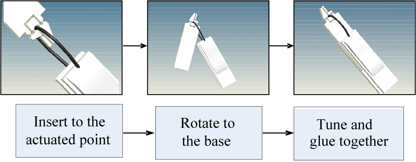
Procedure of assembling SMA actuator and gripper
4. Gripping force in grasping
4.1 Measurement and testing system
The gripping force in the manipulation of a micro rod was measured by the microgripper system. The measurement and testing system was installed as shown in Figure 10. The installed system consisted of an Olympus IX71 inverted microscope, a manipulator with the fabricated microgripper system, fabricated standard weight, STDW2 and a personal computer with display. The STDW2 was 0.4mg. The display was with 640×480 pixels per frame. The image system included JAI CVS3200 CCD, Moritex ML-Z07545D and Matrox Meteor-II image cards. The resolution was adjusted by selecting different object lenses. The overall testing system was controlled by a personal computer (PC) with Intel Pentium D CPU. Matrox software together with an image tracking algorithm was used to convert the image data into a deflection angle. Dynamic images were captured at a 50ms sampling rate.
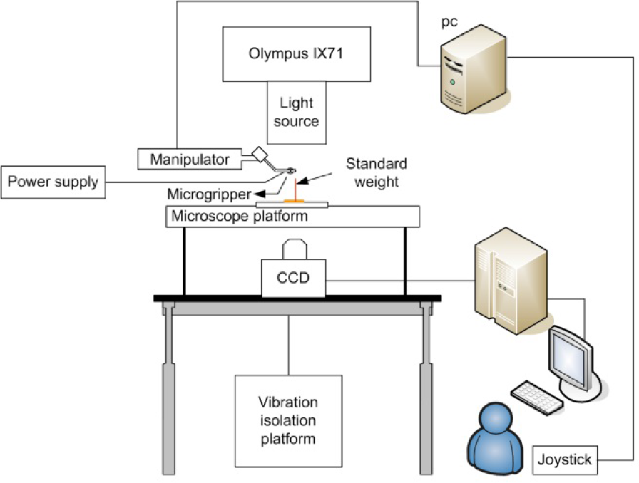
Experimental setup for measurement and calibration of gripping force
The integrated gripping force sensing system needed tests and calibration before proper applications in the manipulation of micro objects. In the experimental tests, the measurement and testing system was controlled and operated at room temperature (26-27°C) and 40-44% humidity.
4.2 Tracking motion of gripper edges
The performance of the tracking algorithm plays a key role in the visual servo system. An effective algorithm of RES (Regional edge statistics) [26] was selected and extended for edge tracking applications. In the ERES (Extended regional edge statistics), the selected window was to enclose only a partial region of the gripper edge instead of a full region of a symmetric image as in RES. In addition, the tracking speed was adaptively adjusted in the ERES instead of utilizing maximum speed in RES.
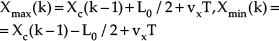
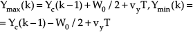
The ERES was employed to find the features of the edge. In the time instant k-1, a tracking window was first constructed with a height of L0 and width of W0. The initial centre of a tracking window in ERES was (Xc(k-1), Yc(k-1)). The centroid of the edge enclosed by the window was selected close to the centre of the window in the initial time instant. The sampling time is T and the tracking velocities in x and y coordinates are given as vx and vy, respectively. In the next time step, the limits of the boundary by height and width, given as Xmax(k) and Xmin(k), and Ymax(k) and Ymin(k), respectively, were predicted by
Then, a 2-D mask was employed to extract the edge features of the target in the tracking window. For a 2-D mask with height 2a and width 2b, the image response G(x, y, k) with a mask W(s, t) on an original image F(x, y, k) is expressed as

The horizontal and vertical Sobel masks (WSobelv(s,t),WSobelh(s,t)) with given appropriate threshold values (VSobelv VSobelh) are utilized to extract the horizontal and vertical edge features of the microgripper. The extracted vertical and horizontal edge features are given by (9) and (10), respectively


From (9) and (10), the set of edge features of the microgripper is extracted to give E(k) as

The ERES algorithm finally utilizes the set of edge features to estimate the centroid of the edge in window, (Xo(k), Yo(k)) as given by the following two equations
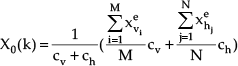

where (xvie,yvie) and (xhje,yhje) are the ith and jth image coordinates of elements in the vertical and horizontal edge features, respectively. Cv and Ch are between 0 and 1 and are given as the statistical weighting coefficients of vertical and horizontal features, respectively. The numbers of elements of vertical and horizontal edge features, respectively, as M and N are counted in the procedure of edge extraction. When the gripper edge is moving one step, the centre of the tracking window is replaced by utilizing (14) and (15)


The application of the ERES algorithm for tracking the motion of microgripper tips was tested and calibrated. By employing the ERES with Cv=1, Ch =0, the centroid of the gripper edge enclosed by the tracking window was estimated and tracked during gripper operation. The accuracy of the estimated coordinates of centroids by ERES was calibrated to give one pixel error [28].
4.3 Estimation of deflection angle in force sensing
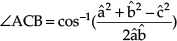
The deflection angle of the force sensing arm was estimated by employing the ERES algorithm and using trigonometric calculation. The application of ERES in specifying the initial tracking windows and estimating the tracking centroids are illustrated in Figure 11(a). The dynamic angle of the sensing arm was estimated by referring to Figure 11(b). With the estimated coordinates of three positions, a line segment as BC̅ along the edge of sensing arm was estimated by employing the least-square method. By utilizing the same approach, another line segment along the reference edge of the sensing arm through points 4 and 5 in Figure 11(a) was constructed as AC̅. Thus, a triangle ABC with â, b̂ and ĉ for the length of three sides BC̅, AC̅, AB̅, respectively, was estimated and the angle of ACB was derived by

ERES algorithm for tracking straight line coordinates; (a) Tracking windows and centroids (b) Tracking straight line
The accuracy in tracking the dynamic angle was tested by sending a current and holding for a period in actuating the SMA of the microgripper. The setting angles were maintained at constant current in two different levels of 86° and 88.3°. The setting angles were also measured directly by utilizing an Auto CAD tool. From the mean value of the tracking angle in stationary, the calibrated result gave an error of 17% by the tracking algorithm [28].
By utilizing the ERES algorithm for tracking the deflection angle of the force sensing arm, the rigid-body mode in the gripper motion need to be eliminated. One approach was to subtract the rigid-body motion obtained from an input-output kinematic model [26]. Another approach was to select a new reference line segment for eliminating the rigid-body motion. A reference line segment of A'C'̅ parallel to AC̅ in the initial position of the deflection arm was constructed as shown in Figure 11(b). By following the same approach as above for estimating the dynamic angle, the length of three sides of triangle A′B′C′ corresponding to the triangle ABC were estimated, respectively. Thus, the deflection angle was obtained by employing (16).
4.4 Gripping force calibration
A simple method was employed for the calibration of the gripping force. In performing experimental tests using the setup of Figure 10, the electrical current to drive the SMA was adjusted to holding the STDW2 firmly. By sending the current to the SMA for gripping the STDW2 and moving the microgripper upward, the position of the STDW2 was monitored until the STDW2 was lifted to leave the sitting plane. Then the current was reduced slowly and the image capture system was initiated to record the dynamic images of the microgripper in gripping condition. The dynamic images were recorded until the STDW2 was released from the gripper jaws and dropped down to the sitting plane. The recorded images were inspected to find out those images which were right before and after dropping the STDW2. From the two recorded images, the deflection angle was obtained and utilized to calculate the moment applied by the gripper jaws. Two measured angles from the images were subtracted to give a positive angle of 1.8°. From the calibrated relation of (5) and with a moment arm 175μm from the specified gripping point, the gripping force was measured as 10.16μN. The force resolution was around 1μN. With a STDW2 of 3.9μN and a friction coefficient of 0.24, measured by the tangent of the friction angle, the calibrated gripping force was 8.19μN. The calibrated results gave an error of gripping force of 24.1%. The error in the overestimated gripping force was due to the deflection angle measurement, estimated friction coefficient, adhesion force, capillary force and fabrication of contact surface in gripping.
5. Gripping force in vision-based control
5.1 Visual servo in grasping tests
The SB-SMA actuating microgripper is operated under the unique ability of recovering its mechanical deformation through an appropriate thermal cycle and elastic deformation by martensitic transformation and residual stress. The thermal and stress-dependent hysteresis behaviour in phase transformation makes precise control difficult. Although there are numerous pieces of research proposed on controlling SMA actuators, precise motion control of an SMA actuator, not to mention a micro one, has not been fully explored [45]. For the SB-SMA actuator, the nonlinear dynamics were modelled as a static hysteresis model multiplied by a pure dynamic model. The hysteresis behaviour was modelled properly by utilizing the Preisach model. However, the behaviour of the SB-SMA microactuator was rather time-varying and experimental data lacked enough precision. For the comparison of different controller designs, three control schemes, which may depend on a precise Preisach model or not, including a PI controller, a PI with feed forward compensation and a fuzzy expert PI (FE-PI) controller were tested [28]. The experimental results revealed that the inclusion of an inverse Preisach compensator improved both the response accuracy and the rising time. Among the three control strategies, the FE-PI achieved the best performance in response accuracy and rising time.
5.2 Gripping force in grasping control
The FE-PI was employed for the closed-loop control in sensing gripping force. The block diagram of the FE-PI for controlling the tip displacement of the microgripper is shown in Figure 12. The design of the FE-PI was to follow the approach of an incremental fuzzy expert PID control [46]. For the FE-PI, the P and I action are given, respectively, by


Block diagram of fuzzy expert PI controller
where CV{e(t),ė(t)} is the output of the fuzzy controller and k1, k2 are adjustable parameters. The membership functions of error, e(t), error rate, de(t) and control input, u(t), were given as triangular functions. The expert knowledge by the fuzzy rule was given by the knowledge base as a fuzzy sliding mode control [28]. The knowledge base is shown in Table 1. In Table 1, the linguistic meaning of error and the error rate are represented by NB, NS, ZE, PS and PB, respectively, for negative big, negative small, zero, positive small and positive big. The fuzzy rules constructed are based on the structure of the sliding mode control. In the diagonal of the knowledge base, the regions can be viewed as a boundary layer of sliding mode control. Therefore, zero control signals are assigned in the diagonal of Table 1. The reaching conditions in sliding mode control are to be satisfied by the knowledge base. The regions below the diagonal are positive and the regions above the diagonal are negative. The magnitude of the control signal in the regions increases when the distance from the diagonal increases and vice versa.
In the FE-PI, the constants were k1=k2=1, ke=0.65, kc=0.1 and ku=10. The tip displacement was estimated by the ERES algorithm with a tracking window specified on the gripper tips. The sampling time in closed-loop control was 37.75ms.
Knowledge base of 25 fuzzy rules


The experiment for sensing gripping force in grasping a micro object was undertaken using the following procedure. At first, a 38μm metal rod was trimmed to be held by the microgripper by applying 5μN force. The gripping force was provided by the gripping arm with 1° deflection. Next, the input position signal was stepped on immediately and then decreased gradually until the metal rod started to move and tilt between the gripper arms. Finally, the input position signal was held constant until the power was turned off.
The experimental results revealed that the FE-PI control tracked the position command and rejected the load disturbance effectively. With the measured deflection angle, the gripping force, with its average in the course of position control, was obtained to give Figure 13. From Figure 13, it can be observed that the maximum gripping force was approximately 58μN. The gripping force decreased to 0μN at 47 seconds. This was due to the increasing opening of the gripper tips until the moment that the metal rod started to tilt and caused the force to undershoot. The disturbance force by the instant movement and impact of the metal rod at 60 seconds was 15μN. The final holding force was around 7μN. The experimental results revealed that the proposed gripper system was employed effectively in grasping a micro object and monitoring micro Newton gripping force. In performing repeated performance tests for a long time, the contact between the gripper and SMA actuator at the actuated point needed to be examined and adjusted to ensure the contact condition during operation.

Estimating gripping force under fuzzy expert PI control
6. Conclusions
A compliant-joint PU microgripper integrated with a force sensing arm was developed to manipulate a micro object using vision-based control. By employing excimer laser ablation on a PU film, a microgripper integrated with a force sensing arm was fabricated. A correlation method was proposed to measure the actuating displacement of the SB-SMA actuator. The SB-SMA actuator was fabricated and assembled to drive the microgripper. In tracking the motion of the microgripper, accurate motion information for the sensing arm was obtained by utilizing a computer-vision method through the ERES algorithm. The gripping force was sensed effectively by utilizing the information from the moment the arm gripped the point together with the deflection angle of the force sensing arm. The calibrated result gave an error of gripping force of 24.1% in the test for holding, lifting and releasing a standard weight of 0.4mg. The performance of sensing micro Newton gripping force in grasping a 38μm metal rod under an FE-PI controller was tested. A disturbance force of 15μN, due to the instant movement and impact of the metal rod in opening jaws, and a holding force of 7μN were sensed by the developed gripper system in manipulating the metal rod.
Footnotes
7. Acknowledgments
The authors would like to thank the NSC for the support under contract No. (97)-2221-E-006-179.