
Abstract
Abstract When moving in generic indoor environments, robotic platforms generally rely solely on information provided by onboard sensors to determine their position and orientation. However, the lack of absolute references often leads to the introduction of severe drifts in estimates computed, making autonomous operations really hard to accomplish. This paper proposes a solution to alleviate the impact of the above issues by combining two vision-based pose estimation techniques working on relative and absolute coordinate systems, respectively. In particular, the unknown ground features in the images that are captured by the vertical camera of a mobile platform are processed by a vision-based odometry algorithm, which is capable of estimating the relative frame-to-frame movements. Then, errors accumulated in the above step are corrected using artificial markers displaced at known positions in the environment. The markers are framed from time to time, which allows the robot to maintain the drifts bounded by additionally providing it with the navigation commands needed for autonomous flight. Accuracy and robustness of the designed technique are demonstrated using an off-the-shelf quadrotor via extensive experimental tests.
Keywords
1. Introduction
The increasing importance of the role played by many kinds of robotic platforms is witnessed not only in the growing amount of research works on this subject in the literature, but also in everyday news about military issues, urban security, territory monitoring, sea exploration operations, and so on, where ever more advanced robotic artefacts are used to support and complement human tasks. Particular attention is especially devoted to Unmanned Aerial Vehicles (UAV), which, thanks to their great versatility, can be exploited in many different contexts. Such contexts generally require the ability to remotely operate the robot [1], although having platforms capable of autonomous flight is often considered of great importance [2]. In order for the robot to be capable of independently exploring the environment, follow a target, perform automatic take-off and landing, etc., it has to be provided in real time with accurate information about its position and orientation in the surrounding world [3]. This goal may be easier to achieve in outdoor environments, where information produced by onboard sensors can be complemented by external data about global positioning. The situation is rather more complex in GPS-denied scenarios (e.g., in the case of indoor flight), where reliable positioning data are often harder to obtain. In this case, orientation, speed and height information generated, for instance, by the inertial measurement unit (IMU), the altimeter, etc., are generally enriched with data extracted from onboard cameras, when available. Hence, various kinds of image processing techniques are used to process images, e.g., in the visible or infrared spectrum, for improving the knowledge about the platform's trim [4, 5]. Unfortunately, the lack of absolute references generally may lead to an accumulation of errors introduced with determining position and orientation [6]. All of the above is particularly critical when working with the lightweight and low-cost flying platforms that have been recently developed. In fact, despite their clear advantages, because of budget and payload constraints the accuracy of sensors available onboard is often very limited.
Taking the above considerations into account, this paper presents a vision-based technique to estimate the six degrees of freedom (6 DoF) describing the trim of an indoor flying robot in absolute coordinates. The devised technique uses the video flow captured by the low-resolution vertical camera of the robotic platform and, on each frame extracted, runs both a marker-less and a marker-based pose estimation algorithm. The marker-less algorithm uses odometry-based methods to determine relative frame-to-frame robot movements by working on changes that occur in visual features present on the floor. It is also designed to look for artificial markers positioned in the explored environment at known positions, thus providing the robot with absolute positioning information. The novel contribution of this paper is in the combination of the above methods, which lets the overall technique fully benefit from their respective advantages. The image feature-based approach allows the platform to explore an unknown environment by supplying the navigation unit with the data required for performing the control, while drifting errors are reset and kept within controlled bounds by means of isolated markers identified by the complementary method.
As said, the focus of this paper is on the vision-based aspects. Hence, in order to study the applicability of the designed technique in a true application scenario with remotely controlled aerial vehicles also capable of autonomous flight, an off-the-shelf quadrotor was chosen, namely the Parrot Ar.Drone (http://ardrone.parrot.com). A control application was developed, using the SDK provided by Parrot, which is capable of receiving the video flow and sensor data from the robot, computing absolute position and rotation, and transmitting suitable navigation commands back to the flying platform. Moreover, the markers exploited for absolute positioning purposes were additionally used as waypoints, by directly linking explicit commands to them. In this way, an autonomous navigation feature (customizable at runtime) was also implemented, which was originally not available for the considered platform. An extensive set of experimental tests was carried out to comprehensively assess system performance. Besides proving the effectiveness of the devised method, the results actually demonstrated how easily and flexibly the devised solution could be extended to other platforms, technologies, and contexts as well.
The rest of the paper is organized as follows. Section 2 reviews the main works in the literature concerning pose estimation methodologies for robot platforms, specifically focusing on vision-based methods. The section also briefly introduces the Ar.Drone. Section 3 describes in detail the marker-based and marker-less techniques that are combined in the overall algorithm. In Section 4, the experimental tests performed are analysed, a suitable working setup is identified and performance is discussed. Finally, conclusions are drawn in Section 5.
2. Related works and technologies
In recent years, a significant number of approaches have been proposed in the literature to address the issue of improving the accuracy of robotic platforms' position and orientation data obtained solely by sensors available onboard. Such approaches can be roughly split into two categories: those that can work without any prior knowledge of the operating environment or any constraint on it, and those which need to rely on the availability of reference information to compute the updated status.
Techniques belonging to the first category generally combine odometry-based motion data gathered by multiple (often vision-based) sensors to alleviate the impact of errors introduced by a single pose estimation technique. This is the case, for instance, in [7], where relative translation and rotation measures gathered by matching frame-to-frame natural features in monocular camera-based images are exploited to improve the reliability of an IMU mounted on a quadrotor UAV during autonomous flight in unknown environments. Usually, robustness is further enhanced by improving the amount and quality of sensor data used. Thus, for instance, in [2] monocular images are replaced by stereo images, enabling a direct computation of 6 DoF absolute movements. Moreover, such a vision-based system is accompanied by a laser odometry, making the overall design suitable for both indoor and outdoor environments. Independent of the specific sensors adopted, solutions like those discussed above commonly merge inertial and odometry-based information into a data fusion stage (often implemented using an extended Kalman filter) in order to obtain the estimates of the platform's configuration. The intrinsic drawback of these approaches is linked to the lack for absolute references that can be used to alleviate the effect of drifts due to the error accumulation.
Solutions in the second category are designed to compute absolute positioning and attitude information by matching online sensor data with offline representations of the environment or with (possibly artificial) easy-to-recognize elements displaced at known positions. This is the case, for instance, with simultaneous location and mapping (SLAM) systems, where a reference map of an unknown and unstructured environment is created during so-called exploratory missions. The format of the map and the algorithm used to perform the matching at runtime clearly depend on the particular sensor/s used in the map-building step. Thus, in [8] laser scan-measures are exploited to create a 2D description of a wall-enclosed indoor environment augmented with obstacles' elevation information; this is later crossed with online measures within a particle filter. When vision-based sensors are exploited, the map defines a visual memory of the environment by storing raw images captured by the camera during the preparatory flight (or a subset of them, referred to as key frames); frame-to-frame comparison and pose estimation is then performed by means of some image matching techniques [4, 9, 10]. Often local image feature descriptors are used, like Harris corners [11] or Lowe's scale-invariant feature transform (SIFT) [12], because of their robustness to position, rotation and scale variations. In some cases, local features are combined with global descriptors (e.g., based on image gradient information, as in [13]) to improve robustness to changes in light conditions and other possible variations in the operating environment. The main limitations of these solutions lie in the fact that significant errors affecting the final estimates can be introduced both in the generation of the pre-recorded description of the initially unexplored environment (only partially mitigated by corrections occurring at loop closures, especially in outdoor environments), as well as in the matching step.
A number of other techniques requiring some reference information have been developed, building on the assumption that the pose estimation step can be improved by relying on some a priori knowledge of representative characteristics of the environment. Again, different characteristics can be considered. For instance, in [14] flight data are compared against a previously available digital elevation map (DEM). In [15] virtual 3D models are used, whereas in [3] robot localization is achieved by exploiting offline multiple pictures of along-path known objects. When a high accuracy is needed, e.g., for indoor flight, natural references are replaced by artificial ones, which can be generally tracked in a more robust way [16]. Thus, in [17] and [18] square targets with a significant contrast with the remaining environment are considered. Better results can be obtained by using special markers (like ARTags [19] or QRCodes [20]), which can deliver additional information to the observer system. Thus, in [21] a flying platform's pose is estimated by exploiting ARTag markers together with information coming from the IMU. Despite the high precision that can be achieved with this technique when at least one marker is framed, severe drift is observed when markers fall completely outside the camera's field of view (also, a sufficient number of markers/a suitable distribution can be hard to guarantee).
The methodology presented in this paper aims to exploit the strengths of each of the macro-approaches introduced above to mitigate their respective weaknesses. It makes use of image features naturally embedded in an unknown environment to compute relative translation and rotation estimates. It then exploits a limited number of artefacts distributed ad hoc in the environment to reset the drift errors introduced by the former technique, and to determine platform's position and attitude in an absolute way. The effectiveness of the proposed approach has been tested with the Ar.Drone quadrotor, which comes with an ultrasound altimeter and two rigidly attached cameras, a wide angle front camera with a 640×480 pixels resolution (18 fps) and a high-speed vertical camera with a 176×144 pixels resolution (60 fps). Camera frames are transmitted over a Wi-Fi link, with an average latency of about 120 ms.
3. The designed visual odometry technique
The vision-based pose estimation method proposed in this paper is implemented as a dynamic library written in C++. Software routines are invoked within a loop that processes the frames gathered from the camera and determines the flying platform's 6 DoF. This information is then exploited by a control unit, a program written in C# and based on the Ar.Drone SDK, which runs on a desktop computer and dynamically links the library. The control unit supervises the communications with the platform. It passes video frames received to the pose estimation library, obtains tracking data, and dispatches them to a navigation module producing control commands for autonomous flight (more details on this latter module can be found in [22]). The control unit also integrates a graphics interface for manual guidance.
3.1 Pose estimation of the robotic platform: an overall view
The overall pose estimation process can be considered as conceptually split into two processing flows, which work on the same frame captured by the vertical camera. One of the flows is devoted to marker-based processing. When a known marker is detected, it is used to determine the position and orientation of the flying platform relative to the marker itself. The other flow, in turn, works on the image features that can be extracted from the unknown environment, and is exploited to perform a separate estimate of the robot's pose. The two flows are designed to be executed in separate threads. A communication channel is established between the two flows, so that the higher accuracy generally associated with the marker-based approach can be used to correct errors that are progressively accumulated by the marker-less technique.
The marker-based tracking flow has been implemented using the ARToolKitPlus library [23], which provides a set of functions for determining the roto-translation matrix describing the relative position and orientation of the camera with respect to the ARTag that is currently framed. A further transformation is required to transform the camera's relative coordinates into absolute word coordinates, i.e., to unambiguously localize and orient the quadrotor in the environment being explored (under the assumption that the marker's absolute coordinates are known). The output of this flow is passed to a switching module, which will be described in the following.
The marker-less tracking flow has been developed using a SIFT-based image matching technique, which exploits robust local feature descriptors to determine the relative transformation between two input images (in this case, the current frame and a reference frame). Images to be matched are processed to extract key points. Each key point is then represented as a feature vector, consisting of image measures that are invariant to image translation, rotation and uniform scaling, and partially invariant to affine distortion and illumination changes. For the SIFT method to work, there must be a sufficient overlap in terms of feature descriptors between the two images, so that a suitable number of matches is found. Since the structure of the environment is not known a priori, the framed surface (the floor, in this case) has to be assumed as planar. Under this assumption, from two consecutive images a translation vector can be computed. In order to determine the multiplication factor required to obtain the relative 6 DoF estimate, continuous information from the onboard altimeter is used, and pixel measures are converted into metric units, as needed. The SIFT-based flow receives absolute pose estimation data from the marker-based flow whenever they are available; in this way, drifting errors accumulated so far by the marker-less tracking can be cleared. Then, the marker-less relative pose estimation has to be converted to global coordinates. For this purpose, the relative roto-translation matrix obtained for a given frame is combined with the marker-based reference matrix, and an absolute measure is produced. Results generated by the SIFT-based tracking method are passed to the switching module as well.
The switching module is responsible for selecting the estimates to be used in the next processing steps, by choosing between those coming from the ARTag and the SIFT-based processing flows. The selection criterion is currently quite trivial: if available, the ARTag measure is chosen; otherwise, the SIFT estimate is selected. The pose estimation algorithm ends up with a filtering stage, where position and orientation estimates are smoothed in order to remove spikes that could possibly hinder the proper behaviour of the navigation routines. The filter has been designed to introduce an extremely limited latency and is therefore relatively simple. More complex approaches could be exploited to implement both the switching function and the filtering stage, e.g., with combined solutions considering historical data, encompassing motion prediction, etc., to introduce a higher degree of control/intelligence in this step, at the cost of a possibly higher latency. In the following, the two flows will be analysed separately.
3.2 ARTag flow
When a new frame is extracted from the video flow transmitted by the quadrotor and is passed to the pose estimation library, a marker detection step is first carried out. This step is particularly important, since its output will be used to control the behaviour of the switching module. A thresholding is initially performed to produce a binary image. A corner detection step is then executed to find the contours of the square shape possibly present in the image. If this operation fails, this means that the camera is not framing a (valid) marker, and the switching module should select the 6 DoF data produced by the marker-less flow. If the operation succeeds, then a marker has been found, and the next marker-aware processing stages are executed. Specifically, the next step consists in identifying the marker, i.e., in finding its unique identifier based on its internal structure (i.e., its black and white sub-blocks). Since each identifier is associated with an absolute position in the 3D world, with this information it will be later possible to locate and orient the robot in the environment using absolute coordinates.
Then, the pose estimation step is actually performed. Here, the roto-translation matrix representing the markers' rotation and translation with respect to the camera is computed. Pose estimation, which is based on the approach in [24], relies on camera calibration parameters that have been obtained for the quadrotor's camera using the Camera Calibration Toolbox for Matlab (http://www.vision.caltech.edu/bouguetj/calib_doc/). The matrix produced is inverted to get the position of the camera relative to the marker. The next step determines the position and orientation of the quadrotor in absolute coordinates. It relies on knowledge of the position and orientation of all the markers in the environment, and allows for the computation of the absolute 6 DoF of the flying platform at the given time. Translation values are expressed in millimetres, and describe the position of the robot with respect to the origin of the reference coordinate system, whereas roll, pitch and yaw angles describe its orientation. The overall ARTag-based pose estimation process, which takes less than 10 ms on an Intel i5 2.3 GHz CPU, is illustrated in Figure 1.

Organization of the marker-based (ARTag) flow
3.3 SIFT flow
The SIFT flow is initiated, like the ARTag flow, with the arrival of a new frame to be processed. According to [12], the SIFT algorithm includes four major stages. The first step consists in the selection of key points, which are defined as maxima and minima of the result of the difference of Gaussian functions applied in scale space to a series of smoothed and resampled images. Poorly representative points (such as low-contrast ones) are discarded, since they would be hard to recognize and match in the next stages. The second step determines the location and scale of every key point, assigns dominant orientations to them and finally creates the associated feature vectors with all the gradient-orientation histogram entries in a region around the key points themselves. In the devised processing flow, the above steps are applied to both the current frame and to a reference frame, thus obtaining two sets of feature vectors. The third step consists in searching for the best candidate match for each feature vector in one of the sets, by identifying its nearest neighbour in the other set based on Euclidean distance. In the fourth step, an affine transformation between all match pairs is estimated using the Hough transform. From the full set of matches, several verification steps are then executed to discard outliers and to identify subsets of high-confidence key points that agree on the geometric transformation giving the best match between the two images.
The algorithm has been developed by using the SiftGPU library (http://cs.unc.edu/˜ccwu/siftgpu/), which implements the SIFT theoretical approach in [12] optimized for parallel processing [25] (delay is less than 30 ms for a 176×144 pixels image on a NVidia GeForce GTX 295). The reference frame is initialized, at system start-up, with the first camera image received, and is later updated when the number of matches goes below a given threshold (i.e., when feature vectors' overlap is not sufficient, frames are blurred, etc.). As will be shown in the following, the threshold has been set in an empirical way based on experimental tests. Basically, a higher threshold requires a higher overlap, and the distance that can be covered without updating the reference is quite limited. On the other hand, a lower threshold allows the maintaining of the same reference over larger distances, at the cost of a reduced number of features for computing the pose estimation when the reference is finally updated. If a sufficient number of correspondences are found, the pose is estimated using matches between these two images. Otherwise, the current frame is compared to the previous one (where, if quadrotor speed is not excessive, a sufficient number of correspondences should be found). If even this attempt fails, an alert is raised to notify the overall system that a pose could not be estimated for the current frame, and an automatic landing is executed.
Pose estimation is based on the method presented in [26], and is implemented relying upon the IVT library (http://ivt.sourceforge.net/). The global position and orientation of the flying platform are finally updated with the contribution determined for the current frame and corrected using absolute pose information from the ARTag-based flow. Errors accumulated in the marker-less flow are inversely proportional to the number of key points in the camera images and directly proportional to the number of updates to the reference frame. The overall SIFT flow is schematized in Figure 2.
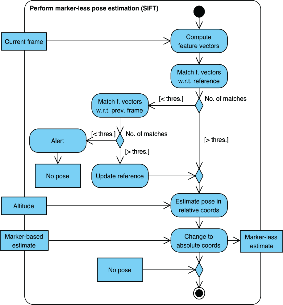
Organization of the marker-less (SIFT) flow
3.4 Configuration of the environment
As illustrated in the previous sections, in order to exploit the dual marker-based/marker-less image processing, the environment has to be configured by placing artificial markers at known positions with known orientations. This will let the ARTag flow estimate the absolute pose of the flying platform in a reference system whose origin corresponds to the centre of one of the markers. This information is stored in a configuration file that reports, for each marker, its unique identifier, the side of the square's edge (in millimetres), and the roto-translation matrix with respect to the absolute coordinate system. The marker defining the origin of the coordinate system has zero rotations and zero translations. An excerpt of a configuration file describing two markers is reported in Figure 3, together with the resulting physical layout.

Configuration file describing two markers located in the environment to be explored by the robotic platform (left) and their physical position and orientation (right)
4. Experimental results and system setup
The performance of the developed approach has been assessed under a number of different conditions. First, the accuracy of the marker-based and marker-less pose estimation methods is characterized separately under static conditions. Then, the estimates produced by the overall algorithm combining the two processing flows are compared with real-time position and orientation measures obtained by an IR tracking system under dynamic conditions. Finally, the integration of the pose estimation system with the navigation module providing flight commands has been empirically experimented.
4.1 Characterization of the marker-based flow
The accuracy in the determination of the (robot) camera's position and orientation with respect to the marker that is framed at a given time is particularly critical, since such information is supposed to be used to correct estimates computed by the marker-less tracking flow as soon as a marker has been detected. Hence, the aims of the tests performed were twofold. On the one hand, the goal was to quantify the main contributions to the pose estimation error, i.e., the error introduced while passing from the detected marker's corners in the framed camera image to position and orientation of the marker itself in the camera reference system (CRS), and, finally, to the position and orientation of the camera in the marker reference system (MRS). On the other hand, the objective was to identify the best working conditions for the particular operating environment and hardware available. When considered as a whole, the above information enables the estimation of the overall accuracy of the marker-based processing flow.
The first tests were performed in static conditions, by framing a 20 cm square marker from a 1 m distance using a camera with a 174×144 pixels resolution (i.e., that of the considered flying platform) facing down and framing the ground. Tests were performed several times under different environmental conditions, and for each test about 2500 frames were captured. Environmental conditions were maintained as stable as possible for the duration of each test. Three plots obtained from one of the tests are illustrated in Figure 4. The plot in the first row reports the values of the roll, pitch and yaw angles in the CRS for the various frames. The plots in the second and third rows show how the position of the detected marker's left corners (second row) and right corners (third row) changes. Even though data were gathered in stable conditions, significant variations can be observed for orientation information, especially concerning the roll and pitch angles (which vary in the range −9 to 6 and −4 to 4 degrees, respectively).

First row: rotation estimates in the CRS for a set of video frames under steady conditions; second and third rows: variation of corners' position in the framed camera image
Looking at the plots, it can be noticed that variations in the pose estimates are directly linked to fluctuations in the detection of corners' positions. These fluctuations, which might be due to small variations in scene illumination, the effect of video compression and other factors, could lead the thresholding algorithm to switch corners' positions over adjacent pixels. An example of this effect is illustrated in Figure 5, where a one-pixel change in the detected corner's position over consecutive frames is outlined (right side of each square in both images).

Pixel error: even in stable conditions, detected corners' positions might undergo discrete changes from frame to frame
It is worth observing that small errors in the identification of true corners' positions are amplified by the change of reference system (i.e., in the matrix inversion step) required to pass from pixel information in the framed image to the CRS. Hence, a single pixel error (in one of the eight neighbouring pixel positions) could translate into a much more significant error over all the 6 DoF. Experimental tests demonstrated that the impact of this error can be reduced by augmenting the resolution of the camera (i.e., reducing the impact of the error on one pixel). In particular, with a 320×240 pixels camera, the error on roll varies in the range 0 to 2 degrees, whereas the error on pitch varies between 0 and 4 degrees. Another possibility could be to increase the size of the marker. Lastly, a further important factor is represented by the camera-marker distance: the larger the distance, the higher the error due to the matrix inversion.
Based on the above observations, other tests were carried out to identify the best trade-off between these parameters and determine the best configuration to be used in the overall system. A physical setup was prepared to keep the marker and the camera centred and on parallel planes, and to vary their distance in the range 40 to 100 cm, steps 10 cm. A number of measures were performed by using a 20, a 30 and a 40 cm marker. The results obtained are illustrated in Figure 6.

Left column: average errors along the X, Y and Z axes in the MRS; right column: errors in the CRS
By comparing the plots in the two columns, the impact of the matrix inversion step on angle errors introduced in the corner detection phase can be easily estimated. In fact, variations in the order of some millimetres are transformed into variations in the order of some centimetres. As expected, the larger the distance, the higher the error. With larger markers, however, the impact of such errors can be effectively reduced. Since the best flying altitude for the Ar.Drone is about 65 cm, the optimal size for a marker's edge is 20 cm. The advantage associated with the use of a larger marker would be limited by the fact that it would easily fall out of the camera's field of view at that altitude (hence, the platform should fly at higher altitudes, with poorer performance). Under such conditions, the error along the X, Y and Z axes varies in the ranges 0.5 to 2.5, 0 to 2, and 1 to 10 mm in the CRS, and 10 to 60, 20 to 70, and 5 to 15 mm in the MRS. The roll, pitch and yaw angles vary in the ranges 1 to 6, 0 to 5, and 0.1 to 0.9 degrees in both the CRS and the MRS.
The last set of tests aimed to characterize the overall accuracy of the ARTag-based pose estimation system (considering a flying altitude of 65 cm and a 20 cm square marker). The focus was on translations along the X and Y axes as well as on rotations around the Z axis (which are more relevant for the platform). Results obtained by moving the camera 15 cm along the X axis or rotating it around the Z axis are illustrated in Figure 7.

Translation of 15 cm along the X axis (first row) and rotation around the Z axis, i.e., yaw angle (second row): average estimate error and standard deviation
4.2 Characterization of the marker-less flow
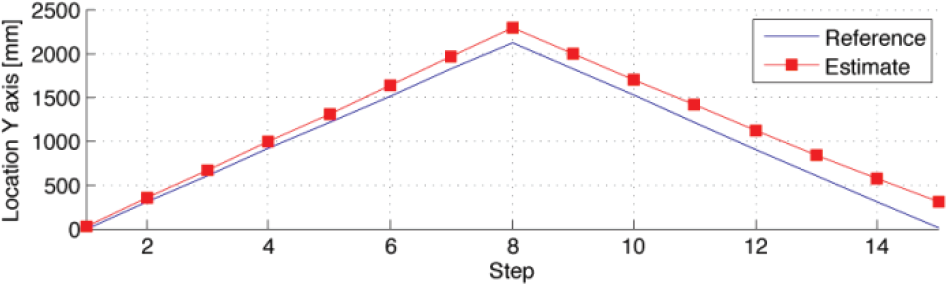
Further tests were performed to study the accuracy of the SIFT-based pose estimation flow, with the aim of finding the operating conditions and configurations potentially able to provide the best performance. A set of measures was gathered by working on images with a resolution of 176×144 pixels while moving the flying platform over a purely straight and planar path. Estimates resulting from the marker-less odometry were compared with reference measures obtained by using a laser meter. Two sample plots comparing results (for a movement along the Y axis, back and forth) over a 1.5 m and 4.5 m approximate total distance are reported in Figures 8 and 9. Here, the effect of the drifting errors can be easily appreciated.

Comparison between laser meter measures and SIFT-based estimates (distance covered about 1.5 m, translation along the Y axis, threshold set to 10 matches, resolution 176×144 pixels)
Comparison between laser meter measures and SIFT-based estimates (distance covered about 4.5 m, translation along the Y axis, threshold set to 10 matches, resolution 176×144 pixels)
As said, the error is due to the fact that relative measures are always referred to a dynamic reference (a frame that is updated based on a quality threshold, or the previous frame), which is relative as well. The lack of an absolute reference makes the distance between the two curves tend towards infinity. This trend is neither proportional to time passed, nor exactly proportional to distance covered. In fact, drifting error is related to the number of updates to the reference image, and becomes particularly high when the update is performed (hence, the error does not grow in steady conditions). As can be seen by comparing Figure 8 and Figure 9, the error grows linearly, and with the same reference update threshold (minimum number of matches) its impact is more evident over larger distances. An interesting question is, therefore, how to set up the update threshold. To answer this question, the above tests based on a threshold equal to 10 were repeated by varying the threshold. A plot obtained with the threshold set to 40 is shown in Figure 10.

Comparison between laser meter measures and SIFT-based estimates (distance covered about 4.5 m, translation along the Y axis, threshold set to 40 matches, resolution 176×144 pixels)
The results show that the distance between the SIFT estimate and the laser meter measure becomes larger and larger as the threshold value grows, thus suggesting that it is preferable to accept a worse estimate when the reference is updated, but to limit the number of updates.
The tests described above were repeated by using a camera with a higher resolution in order to study the best configuration for robots that might be different from the one considered in the current paper. A camera with a 640×360 resolution was used. Considering Figure 11, which has been obtained by using a threshold once again set to 40, it is immediately evident how performance significantly improves with a larger resolution.

Comparison between laser meter measures and SIFT-based estimates (distance covered about 4.5 m, translation along the Y axis, threshold set to 40 matches, resolution 640×360 pixels)
This is due to the fact that, with a higher resolution, the number of key points computed on a given image (and the number of matches) grows. In fact, working with the 176×144 pixels camera, the average number of key points per frame was about 120. With the 640×360 pixels camera, this number was four times larger. Thus, with the 176×144 pixels camera, the average (maximum) error was about 65 mm (145 mm) over the 1.5 m distance and about 155 mm (273 mm) over the 4.5 m distance. With the 640×360 pixels camera, over the 4.5 m distance the average (maximum) error was roughly 29 mm (48 mm).
4.3 Overall characterization with an IR tracking reference
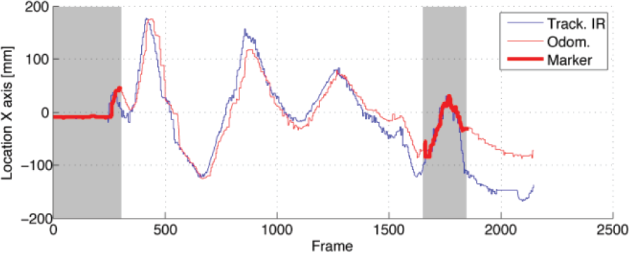
The goal of the last experimental tests performed was to evaluate the performance of the combined marker-based/marker-less tracking method during controlled flight. In the tests, the quadrotor was guided by means of suitable commands issued by the navigation module. ARTag and SIFT-based tracking data were acquired over ten-minute flying sessions. The robot was equipped with passive IR reflective markers and followed with an external IR tracking system [27]. This way, position and orientation data produced by means of the proposed pose estimation approach were compared to reference values. The configuration found in the previous sub-sections was used. Tests were conducted using an artificially created ground surface to roughly control the number of key points (it has been proved that such a parameter has a critical impact on the accuracy of the marker-less tracking) 1 . A single marker has been placed in the environment, which resets the drifting error when framed by the robot's camera. Plots of the estimates obtained by the proposed system and of IR tracking measures for the translation along X and Y axes, as well as for the rotation around the Z axis, are reported in Figure 12. The frames where the marker is detected are indicated by thicker curve points and darker background.

Estimates obtained with the designed visual odometry system compared to IR tracking: translation along the X axis (first row), translation along the Z axis (second row) and rotation along the Z axis, yaw (third row)
The results in Figure 12 can be easily compared with those in Figure 13, where estimates for a translation along the X axis over a ground with 1/3 of the key points in the previous experiments are reported. Here, the frames where drifting errors are reset by using information from the framed marker can be easily observed. In fact, when a marker is framed at the beginning of the flight, estimates and reference measures roughly correspond. Then, the distance between the two measures starts to increase. However, when the marker is framed again around frame 1650, the error falls back into the 50 mm range.
Ground with limited number of features: estimates by the proposed system and IR measures (translation along the X axis) to be compared with results in Figure 12 (first row)
6. Conclusion and future work
In this paper, a monocular camera pose estimation technique was presented combining a marker-less visual odometry algorithm exploiting SIFT descriptors with a marker-based tracking method relying on ARTag markers.
The designed technique can be exploited to estimate position and orientation of an off-the-shelf quadrotor platform, and to endow it with autonomous flight capabilities. The marker-less feature-based pose estimation algorithm has the benefit of being able to incrementally estimate the quadrotor's 6 DoF from the take-off location without knowing a priori any characteristics of the surrounding environment. The main drawback of this approach is that it is heavily influenced by drifting errors. The marker-based pose estimation algorithm, meanwhile, has the clear advantage of being more precise than the feature-based one. Its main drawback is that for the correct functioning, the environment should contain artificial references (at known positions). By coupling the two approaches, a novel approach is obtained that can provide the robot with absolute coordinates and maintain drifting errors within an acceptable range by resetting them when a marker is detected. Experimental tests showed that, by means of the proposed approach, even low-cost flying platforms could be used for purposes different than entertainment.
Future work will aim to further improve system performance by introducing a SLAM technique into the overall algorithm. This will provide the pose estimation system with additional references to achieve more accurate estimates. Moreover, the switching and filtering stages following the two vision-based processing flows will be improved by replacing the simple functions currently used with predictive filtering. In the experimental tests, control was performed at 10 Hz (with a total processing latency below 200 ms), which proved to be adequate for the considered quadrotor. Nonetheless, the application of the devised technique to other robotic platforms might require the discovery of more sophisticated ways to deal with the effect of processing and communication latencies, thus achieving quicker feedback in the closed-loop control. Finally, an approach designed to look for (and not just accidentally discover) markers will be developed: this would allow clearing drifts in a systematic rather than a random way.
7. Acknowledgments
The authors wish to thank Andrea Faccio and Francesco Cosentino for the integration effort provided during the implementation of the overall system.
Footnotes
1
Two videos (for manual and autonomous flight) are available at http://youtu.be/f0c5pb3QzME and ![]()