
Abstract
The intelligent handheld instrument, ITrem2, enhances manual positioning accuracy by cancelling erroneous hand movements and, at the same time, provides automatic micromanipulation functions. Visual data is acquired from a high speed monovision camera attached to the optical surgical microscope and acceleration measurements are acquired from the inertial measurement unit (IMU) on board ITrem2. Tremor estimation and canceling is implemented via Band-limited Multiple Fourier Linear Combiner (BMFLC) filter. The piezoelectric actuated micromanipulator in ITrem2 generates the 3D motion to compensate erroneous hand motion. Preliminary bench-top 2-DOF experiments have been conducted. The error motions simulated by a motion stage is reduced by 67% for multiple frequency oscillatory motions and 56.16% for pre-conditioned recorded physiological tremor.
1. Introduction
Normal human hand movement contains involuntary components including physiological tremor [1], jerk [2] and low frequency drift [3]. The presence of erroneous involuntary hand movements limits the surgeon's micromanipulation accuracy. Many delicate surgical procedures are considered infeasible because of these inherent limitations [4]. Among these involuntary motions, physiological tremor has the most significant effect, because jerk only happens rarely and drift can be partly corrected by human vision feedback [5]. The dominant frequencies of physiological tremor lie between 8 Hz to 12 Hz band [6] with peak-to-peak amplitudes as large as 50 µm [7].
These problems can be overcome by replacing human hands with robotic systems, such as the commercially available telerobotic surgical system “da Vinci” from Intuitive Surgical, Inc. [8, 9]. This approach, though effective, is costly and obtrusive from the point of view of a surgeon [10]. Another approach is the “steady-hand” robotic systems [11], in which a robot and a surgeon directly manipulate the same tool. The system has both the precision of a machine and the manipulative transparency of handheld tools. However, the dexterity and degree of freedom are strictly restricted by the robot arm. In order to further reduce cost, and to maximize the ease of use, user acceptance, and compatibility with current surgical practice, the handheld instrument approach for physiological tremor compensation was proposed by Bose et al. [12]. In this approach, sensing and the manipulator systems are implemented within a completely handheld instrument. The sensing system senses the motion of the instrument body, and the manipulator system controls the tool tip to compensate the erroneous motion. Existing devices based on this approach include Micron [13, 14], and ITrem [15–17].
Micron maintains the instrument size and weight as close as possible to those of existing passive instruments. An optical position measurement subsystem acquires the tool pose and Micron eliminates involuntary hand motion such as tremor by actuating the tip against the undesired motion. ITrem is a more compact handheld instrument with an improved sensing system using only analog accelerometers. Unlike Micron, the sensing subsystem is non-obtrusive since the sensors are internally-referenced and are light in weight and mounted inside the instrument body. Inertial sensing provides movement information at high sampling rate but it tends to lose accuracy over time. Therefore, it is suitable for sensing tremor which is a high frequency component in erroneous hand movement. But it is not suitable for low frequency hand motion, because the magnitudes of hand drift and intended motion in acceleration domain are too small to be sensed by accelerometer [18].
In this paper, we propose an improved handheld instrument, ITrem2, which incorporates real-time vision system and the inertial measurement unit. In addition to physiological tremor cancellation, ITrem2 can further reduce the error due to hand drift and allows automatic micromanipulation functions.
2. Design of ITrem2
In this approach, the inertial sensors are used to nullify high frequency erroneous hand motion and the vision feedback is used for visual servo control as shown in Figure 1.
ITrem2 contains two main parts, sensing and actuation systems. The sensing system consists of two subsystems, the inertial measurement subsystem and the vision subsystem. The inertial measurement subsystem embedded in ITrem2 senses its own motion. This inertial information is used to cancel the physiological tremor. The vision subsystem has a high speed camera mounted on the surgical microscope. The measurements from the vision subsystem are used to control the tool tip of ITrem2 in micrometer scale accuracy. The functional block diagram of ITrem2 is shown in Figure 2.

The block diagram of ITrem2.

Functional block diagram of ITrem2
2.1 The Actuation System
The actuation system of ITrem2 is a 3-DOF piezo-driven micromanipulator, which drives the tool tip in real-time to nullify the erroneous motion and to position it to the desired target. The employed micromanipulator is based on a serial mechanism (see Figure 3(a) and 3(b)) which consists of two shearing, two longitudinal piezoelectric actuators, one flexural lever, one translational flexure and a housing. Translational motions in X and Y axes are generated using a two-axis shearing actuators (P152.10 from Physik Instrumente) incorporating a flexure lever. When the shearing actuator moves in the X or Y direction, a magnified displacement in the -X or -Y direction will occur at the free end of the lever. Two longitudinal actuators (P885.90 and P885.50 from Physik Instrumente) are stacked together to meet the required travel range of 50 µm. They are placed behind the shearing actuators through the translational flexure. One end of longitudinal actuators is connected to the fixed housing, while the other end pushes the translational flexure and moves the shearing actuators in the Z (axial) direction. The translation flexure is made of stainless steel thereby providing sufficient stiffness for pre-loading the longitudinal actuators. The actuation system can produce translational motions of 80 µm along the X-axis and Y-axis, and 50 µm along the Z-axis. Detailed design and performances of the micromanipulator can be found in [19].

Design of the serial mechanism, (a) sketch and (b) photo
2.2 The Sensing System
2.2.1 The Vision Unit
The vision subsystem searches the tool tip in each acquired image using template matching. At first, an image template that represents the tool tip is created. The template matching gives the coordinate positions of the tool tip in the pixel reference frame, PP = [PX PY]T, in sub-pixel accuracy.
There are several focusing algorithms available to estimate the distance of the tool tip from the center of the objective lens based on the blurriness of an image [20]. Among them, the Normalized Variance method is mentioned to provide the best overall performance. Calibration is done to relate the focus value of the tool tip and MZ, the distance along the Z-axis of the microscope reference frame.
After calibration, MZ in the microscope reference frame can be solved on-line from the focus value calculation of the tool tip using the Normalized Variance method. Considering the efficiency of the numerical calculation, the parabola-fitting approximation [21] is used instead of a brute-force approach. These focus values along the Zaxis are modeled by a least squares fit of a second order polynomial as a function of the distance and is shown in (1).

where c2, c1, and c0 are the coefficients of the polynomial. Currently, the achieved resolution of our vision subsystem along the Z-axis of the microscope reference frame does not satisfy our targeted positioning accuracy. This paper focuses on incorporating computer vision and inertial sensing to perform automatic micromanipulation tasks and at the same time suppressing erroneous hand motion. Consequently, the experiments are carried out in 2 D, confining the position of the tool tip to be within the X-Y plane of the microscope reference frame.
Once we get the coordinate positions of the tool tip in the pixel reference frame (PP = [PX PY]T, and the position along the Z-axis of the microscope reference frame (MZ), the X coordinate position and Y coordinate position of the tool tip in the microscope reference frame, denoted by MX and MY, can be calculated using (4). If

and

where pij is the element of perspective projection matrix at ith row and jth column, MX and MY are obtained from

The resolution of the vision subsystem along the X-axis and Y-axis of the microscope reference frame is 1 µm.
2.2.2 The Inertial Measurement Unit
The frame attached to the body of ITrem2 is represented by the body reference frame, {B}. The rotation matrix which brings the corresponding axes of the body reference frame and the microscope reference frame onto each other is denoted by MRB. Then the coordinate transformation of the tool tip acceleration from the body reference frame to the microscope reference frame can be represented by (5).

where MfB represents the function that performs coordinate transformation. Since the body reference frame on the instrument is moving with respect to the microscope reference frame, the rotation matrix, MRB, is updated at each sample point using Z-Y-Z Euler Angle Sequence.
At first, the X-Y plane of the microscope reference frame is manually calibrated to be aligned to the horizontal plane using a digital inclinometer. The accuracy of the digital LCD inclinometer (667-3916, RS Component) is ±0.1°. Therefore, the Z-axis of the microscope reference frame is aligned to the gravity,
The dual-axis miniature digital MEMS accelerometers fixed on ITrem2 are used to detect the tilt angle rotation, MβY, about MY axis and roll rotation, MγZ, about MZ axis. The tilt sensing method using the nonlinear regression model of the low-g MEMS accelerometer [22] is used to reduce the sensing error almost to the level of stochastic noise.
Pan angle rotation is obtained from the orientation of the tool tip image of ITrem2 in the pixel reference frame. The two corner points of the template in the edge based geometric template matching are used to estimate the pan angle rotation, MαZ, about the Z-axis of the microscope reference frame.
The erroneous and involuntary hand movement consists of both low frequency and high frequency motion components. Although the vision subsystem can eliminate the low frequency erroneous motion components, the average sensing delay of 12 ms associated with the vision subsystem impedes its usefulness against high frequency erroneous motion components such as physiological tremor.
To overcome the problem of real-time error cancellation, the BMFLC [23, 24] approach is utilized. It tracks a predetermined band of multiple dominant frequencies based on the prior knowledge of the desired signal. The adaption process is achieved using least mean square (LMS) optimization. As the frequency components in BMFLC are constant, analytical integration can be employed to obtain the displacement from acceleration. For this reason, it is an ideal choice for tremor filtering when data is sensed with accelerometers. To estimate the tremor signal in the predefined band [ω1 –ωn], a series comprising sine and cosine components are combined to form band-limited multiple-Fourier linear combiner:
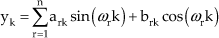
where yk denotes the estimated signal at sampling instant k, and ark and brk represent the adaptive weights corresponding to the frequency ωr at instant k [25].
3. Experiment
3.1 Setup
The experimental setup is shown in Figure 4. The vision subsystem consists of a table top optical surgical microscope (Leica M651 MSD, Leica Microsystem GmbH, Germany) with a built-in coaxial illuminator retrofitted with a camera (Basler piA640 −210gm/gc, Basler AG, Germany). The magnification of the achromatic objective lens of the microscope is 25 and its focal length is 200 mm. The control unit for the built-in illuminator allows continuous adjustment of the light intensity. The microscope is equipped with a beamsplitter and a stereo attachment for a second observer. Therefore the workspace can be viewed simultaneously by the camera, a surgeon, and an assistant.
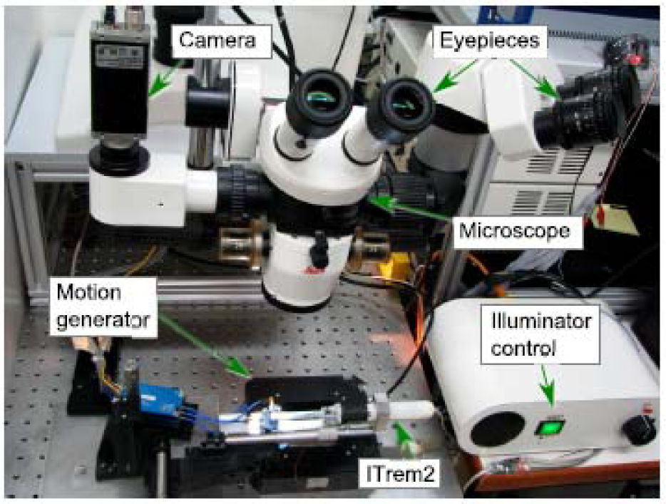
Experiment setup of microscope, camera and motion generator.
The image sensor inside the camera is a Kodak CCD sensor and its resolution is 640 × 480 pixels. This provides a workspace view of 5 mm × 3.7 mm. To obtain good quality images with an acceptable noise level, we used an exposure time of 5 ms and the sampling rate of the vision subsystem is 200 Hz.
Real-time image processing is performed on the NI PXIe-8130 real-time embedded computer connected to the camera via the Gigabit Ethernet interface. The IMAQ Vision for LabVIEW™ is used to implement the template matching and it gives the position of the tool tip in sub-pixel accuracy.
There are four dual-axis digital miniature MEMS accelerometers (ADIS16003, Analog Devices, USA) placed inside ITrem2. The embedded microcontroller (AT89C51CC03, Atmel, USA) on board ITrem2 reads the measurements from the accelerometers at 666 Hz. After performing a moving average filtering, the microcontroller sends the acceleration data to the real-time computer at 333 samples per second. The CAN (Controller-area network) interface with a bandwidth of 500 kbps is used to achieve robust and real-time communication between ITrem2 and the real-time computer. The real-time computer deploys a first-order digital Butterworth bandpass filter to filter out the effects of accelerometer drift, gravity, and noise.
Since, the measurement of the tool tip position for the error analysis need not be real-time, the measurement is taken using the unfiltered tool tip position provided by the vision system.
3.2 Visual Servo Control
ITrem2 uses position based visual servo control [26] integrated with inertial sensing to fulfill the need for hard real-timeliness in microsurgery. The vision subsystem has a mono-vision camera mounted on the microscope which is located at a fixed position in the workspace. It captures the tool tip images at the sampling rate of 200 Hz. The inertial sensors are mounted inside ITrem2 to sense the hand movement. The coordinate transformation of the tool tip position from the tool tip reference frame, {T}, to the body reference frame attached to ITrem2 is represented by

where BfT refers the coordinate transformation from the tool tip reference frame to the body reference frame. Then the position, MP, relative to the microscope reference frame may be computed from the corresponding position, TP, in the tool tip reference frame by using a composition of coordinate transformations,


While the accelerometers sense the uncompensated body movement of the instrument, the vision subsystem detects the compensated position of the tool tip. That is why our algorithm also needs the controlled value, BfT, which specifies coordinate transformation from the body reference frame to the tool tip reference frame. For a point-to-point positioning task in which the tool tip at MP is to be brought to a desired target location, MS in the microscope reference frame, the error function may be defined as

where the coordinate transformation from the tool tip reference frame to the body reference frame, TfB, is the value to be controlled. The control input to be computed is the desired micromanipulator translational movement,

where K is a proportional feedback gain. The proportional control law will drive the tool tip so that the value of the error function is zero.
3.3 Results
The experiment has been carried out to test its performance on physiological tremor cancellation and snap-to target function. ITrem2 is fixed firmly to the motion generator. Motion that consists of both high frequency and low frequency components is generated along the X-axis of the microscope reference frame. The high frequency component of 10 Hz with 50 µm peak-to-peak sinusoidal is used to create a representation of physiological tremor and the low frequency component of 0.5 Hz with 40 µm peak-to-peak sinusoidal is used to simulate hand motion drift. First, the piezoelectric manipulator is turned off and the RMSE of the uncompensated motion is 24.4 µm.
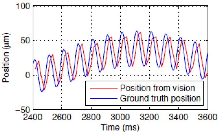
Ground truth position of the tool tip, and the position from vision.
The ground truth position of the tool tip along the X-axis of the microscope reference frame measured by the capacitive sensor as opposed to the measurements from the vision subsystem is shown in Figure 5. There is a significant delay in the vision information because the vision subsystem requires sufficient exposure time to acquire images with acceptable noise level and substantial image processing to identify the tool tip. This inherent delay in the vision subsystem is too long for the physiological tremor to be compensated in real time [27]. That is why ITrem2 uses a BMFLC filter and compensate the physiological tremor while the position based visual servo control of the vision subsystem performs automatic visual servoing tasks.
Acceleration readings from the accelerometers consists of several components due to tremor, intended motion, accelerometer drift, gravity and noise. To obtain the acceleration reading due to high frequency erroneous hand movement only and to filter out other components, ITrem2 deploys a first-order digital Butterworth bandpass filter and a BMFLC filter. Estimation of tremulous motion for real-time tremor compensation is performed by the BMFLC filter that tracks the modulated signals with multiple frequency components. Thereafter, the manipulator is turned on to perform the snap-to function of the tool tip at two different positions. The resulting waveform of the 1D motion canceling test in the X-axis over a period of 10 seconds is shown in Figure 6. The RMSE of the compensated motion is 8.12 µm.

The waveform showing the result of the snap-to function.

The tool tip position versus time along (a) X-axis and (b) Y-axis. The manipulator is engaged at time t1 to enable error compensation.

Position of the tool tip on X-Y plane versus time showing the result of the manipulator engagement at time t1.
The experiment for 2D error canceling has been conducted also. Figure 7 and Figure 8 show the tool tip position along X-axis and Y-axis of the microscope reference frame versus time for the 2D error canceling test.

The tool tip position on X-Y plane (a) before and (b) after 2D error canceling.
Figure 9 shows the tool tip position on the X-Y plane of the microscope reference frame before and after the micromanipulator is turned on to perform 2D error canceling.
Finally, recorded physiological tremor data is used to test the performance of error canceling and the snap-to function. The tremor data is obtained from the surgical instrument tip motion measured during micromanipulation tasks using the micro motion sensing system (M2S2) [28]. The instrument tip motion data is filtered off-line using an off-line zero-phase bandpass filter having a passband of 5–15 Hz to obtain physiological tremor and remove non-tremulous components such as intended motion, sensor noise, and measurement noise. To acquire a motion data that has both low frequency and high frequency components, the filtered physiological tremor data is deliberately superimposed with low frequency sinusoidal components. The resulting motion data is used by the motion generator to produce simulated erroneous hand movements.

(a) The tool tip acceleration, and (b) the position output of the BMFLC filter.
The X-axis acceleration output from the first-order digital Butterworth bandpass filter and the output of the BMFLC filter over a period of 2.5 seconds are shown in Figure 10. The result of the error canceling test using recorded physiological tremor is shown in Figure 11. The RMSE of the uncompensated and compensated motion is 16.25 µm and 7.12 µm respectively.

The resulting tool tip position showing physiological tremor cancellation.
The experiment results with respect to error compensation performance of ITrem2 using multiple frequency oscillatory motions and real physiological tremor are summarized in Table 1.
The error compensation performance of ITrem2

4. Conclusion
The design and implementation of an intelligent hand-held microsurgical instrument for accuracy enhancement, ITrem2, is presented. ITrem2 is designed to perform automatic visual servoing tasks and, at the same time, reduce the erroneous tremulous hand motion. A 3-DOF piezo-driven serial mechanism based micromanipulator is developed which cancels the erroneous hand motion and positions the tool tip to the desired target. The vision subsystem handles the low frequency erroneous motion components, while the inertial measurement subsystem complements the vision subsystem by effectively measuring the high frequency tremulous hand movement in real-time using a BMFLC filter. Preliminary 2-DOF bench-top experiments have been conducted to test the performance of ITrem2. The bench-top test results show that the error motion is reduced by 67% for multiple frequency oscillatory motions and 56.16% for pre-conditioned recorded physiological tremor. Although the bench-top test shows promising results, there is still a large gap between this and real handheld error cancellation. Several technical and research issues need to be solved. The setup is limited to 2-DOF in-plane movement cancellation with the instrument aligned with the microscope reference frame. In a real handheld situation, the instrument body moves freely in space. To obtain the 3-DOF motion at the tool tip, full 6-DOF motion sensing of the instrument body needs to be carried out. Currently, the sensing system is sensitive to disturbance. Therefore, it does not perform well with unfiltered real hand moments. Further investigation on the sensitivity and stability of the BMFLC filter needs to be conducted.
Footnotes
12. Acknowledgements
Vision-Aided Active Handheld Instrument for Microsurgery project is funded by Agency for Science, Technology & Research (A*STAR) and the College of Engineering, Nanyang Technological University. The authors thank them for the financial support of this work.