
Abstract
In this paper we present a practical approach for generating an occlusion-free textured 3D map of urban facades by the synergistic use of terrestrial images, 3D point clouds and area-based information. Particularly in dense urban environments, the high presence of urban objects in front of the facades causes significant difficulties for several stages in computational building modeling. Major challenges lie on the one hand in extracting complete 3D facade quadrilateral delimitations and on the other hand in generating occlusion-free facade textures. For these reasons, we describe a straightforward approach for completing and recovering facade geometry and textures by exploiting the data complementarity of terrestrial multi-source imagery and area-based information.
Keywords
1. Introduction
Nowadays, developments of Mobile Mapping Systems equipped with direct georeferencing devices are revolutionising the mapping world (e.g., [1, 2]). These MMSs acquire rich and massive multi-source data at street level that can be useful to break down some barriers for significantly enhancing the quality of urban facade maps at wide scale. We describe below some current mapping constraints that can potentially be overcome.
Mobile Mapping System, protocol and devices of acquisition.
For solving part of these problems that are particularly common in dense urban environments, we propose a synergistic approach in which heterogeneous cartographic data greatly take advantage of each-others strengths for generating accurate 3D facade quadrilaterals (e.g., [1]) as well as occlusion-free facade textures that correctly match at this level of representation (planar models).
The produced textured facade models can be useful information for many applications such as virtual navigation, autonomous navigation (e.g., [7, 8]) and intelligent transportation systems (e.g., [9]). Indeed, vision-based map-less navigation can exploit the set of textured facades in order to match the on-board acquired images with the corresponding georeferenced facades. This results in a positioning system that is only based on images (e.g., [10]).
2. Operating Mobile Mapping System
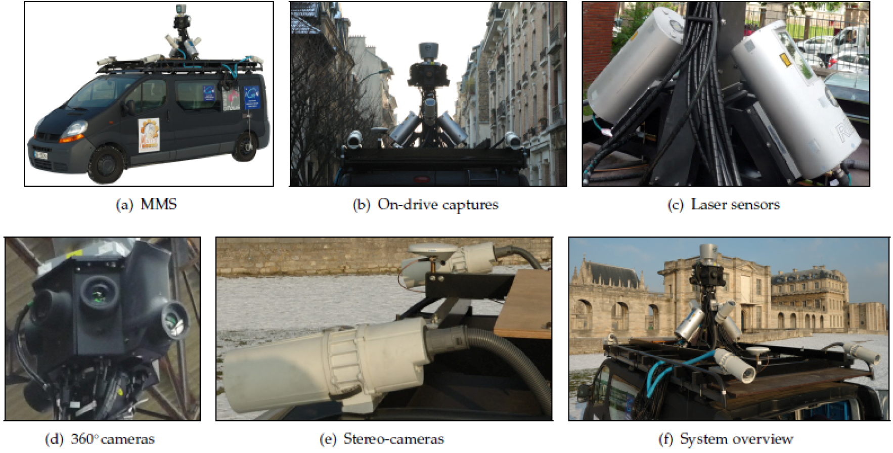
Here, the MMS (see Fig.1(a)) is equipped with two high precision 2D laser sensors RIEGL LMS-Q120i (see Fig.1(c)). These laser sensors are positioned at the mast of the vehicle (see Fig.1(b)) and respectively oriented to each street side in direction of the facades. Their beam plane is perpendicular to the vehicle trajectory. The system allows us to carry out up to 10000 measurements per second and the beam vertically sweeps with an opening of ∡α = 80° (–20° to 60° with respect to the horizontal). This vertical sweeping provides a frame of points (i.e., range or profile). The angular resolution was configured to 201 points per frame. The nominal accuracy of the laser-based measurements is approximately 3cm at 150m. The laser sampling is approximately one point each 5cm to 10cm in planimetry and altimetry when the vehicule moves at 30km/h. These sensors are used for the geometric modeling of building facades. The MMS masthead (Fig.1(b)) is composed of eight cameras that are oriented in cardinal and ordinal directions in order to cover the scene at 360° (see Fig.1(d)). Two additional cameras are laterally located with an angular sloping ∡β = 45° in direction of the top of the facade. The vehicle is also equipped with two stereoscopic acquisition systems located in the front and in the back of the vehicle and oriented in direction of the road (see Fig.1(e) and Fig.1(b)). All these cameras are Full HD AVT Pike 210C digital cameras that acquire 16bit RGB images in 1920 × 1080, namely around 20M̄ of pixels. The Ground Sample Distance of these images can reach up to ⋍ 5cm GSD. The cadence of acquisition is one capture each 4.5m or each 10s (grouped captures). These cameras are used in the texturing of facade models. Besides, positioning instruments are used for georeferencing all the collected data. An overall view of image and laser sensors mentioned above is exhibited in Figure 1(f).
3. Proposed Approach
3.1 Primary Street Point Cloud Segmentation
3.1.1 Accumulation Map Generation (Euclidean)
The verticalness of the street facade walls and other vertical urban objects is exploited. A 2D accumulation map is generated by projecting the 3D point cloud vertically into an horizontal regular grid, i.e. map of accumulation noted A

Results of the primary street point cloud segmentation.
3.1.2 Map-based Segmentation into Vertical and Surface Clusters
A global density threshold is applied to the cells (
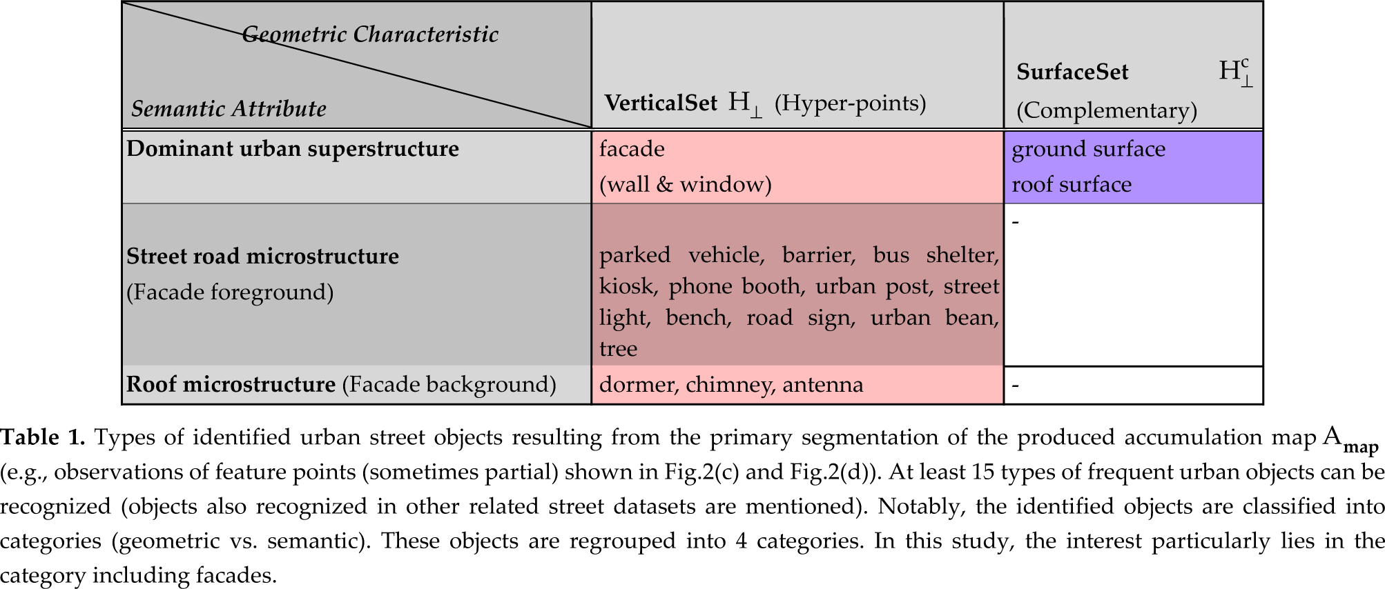
Types of identified urban street objects resulting from the primary segmentation of the produced accumulation map A

3.2 Extracting Clusters and Estimating 3D Quadrilateral Delimitations of Urban Facades
Many cities and large capitals throughout the world detain standard building maps that have been produced by surveyors. These maps that are often composed of georeferenced facade segments derived from measurements carried out from laser-based tachymeters. Notably, the
3.2.1 Focusing on Facade Regions by Exploiting Existing Digital Cadastral Maps
Here, a standard

Results of the facade cluster individualization and extraction as well as segmentation of the corresponding facade images from laser-based estimation of the 3D facade quadrilaterals and projection.
3.2.2 Extracting Disjoint Facade Clusters by Fusing Amap and Cmap Information
The C
3.2.3 Delimiting Vertices of Facade Quadrilateral in Planimetry and Altimetry
For each retained facade cluster (see Fig.3(c)), the associated dominant vertical facace plane can be estimated by applying a conventional
Besides, we emphasize that the generated 3D facade quadrilaterals are derived from the C
In Table 2, we quantify the geometric accuracy associated with the generated 3D facade quadrilaterals by comparison with a set of corresponding 3D facade quadrilaterals produced by using the IGN aerial-based modeling pipeline (national standard ground truth). This evaluation is conducted over 25 facades in a part of the 12 th district of Paris. The deviations in planimetry correspond here to the deviations of distance in the (x,y) plane between the extremities of the facade models provided by our ground truth and those of the generated facade models. We mention that the deviation in altimetry (i.e., in altitude) has not been estimated here since our laser dataset was incomplete at facade bottom and/or at facade top in the available ground truth area due to the acquisition specifications. However, we expect that the relative height of facades are estimated with high accuracy due to the accurate laser data.
Comparison between modeling results over 25 facades estimated from terrestrial laser data (best dataset) and their ground-truth models produced by the IGN aerial-based modeling pipeline. The evaluation area deals with a part of the 12 th district of Paris.
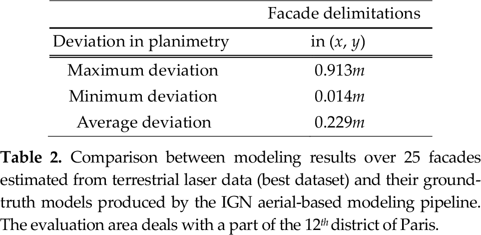
In planimetry, the maximum deviation can reach 0.913m. This deviation can occur in reason of certain cadastral-based facade segment that can be inaccurate. The average and the minimum deviation respectively are of 0.229m and 0.014m. It denotes then that the estimated facade planes are relatively accurate. However, it is worth pointing out the fact that this ground truth is relatively biased since based on the use of a noisy cadastral map and aerial-based noisy data. Furthermore, the accuracy of these delimitations can strongly vary according to some factors such as the GPS information, the intrinsic and extrinsic calibration accuracies of the multi-source sensors, the synchronisation between the positioning systems and the acquisition sensors (vehicle georeferencing), to name a few. Nonetheless, the global topology of the generated wire-frame model appears coherent and the deviation measured in this area are included in a submetric bounded interval. Also, we argue that the generated wire-frame model derived from the terrestrial laser data should be more accurate (ground-based data) since the details between the facade planes are more perceptible (from dense laser data) and since the acquisition is carried out in one single pass. More details regarding this evalutation can be found in [13].
3.3 Recovering Quasi-real Occlusion-free Facade Textures
Frequently, facade models are textured by a mapping with frontal or oblique views of buildings. However, these images can be strongly occluded as shown in Fig.4(a). First questions that come to mind in case of an automatic occlusion-free facade texturing can be as follows:

Results of the occluding facade point detection by exploiting previously estimated 3D facade quadrilaterals.
3.3.1 Detecting Occluding Objects of Urban Facades
The occluding objects that are observed in the images of facades (e.g., Fig.4(a)) can be detected in the laser data at facade level. This is achieved by identifying that the laser beam is intersected by intermediary occluding objects located between the point of acquisition and the previously estimated facade planes (e.g., street road microstructures described in Tab.(1)). The missing facade laser parts can be qualified as laser shadows and this effect is strongly visible in case of occluding trees since they clearly cause elliptic holes in the facade point cloud (see Figure 4(b)). For this stage, the facade planes have been previously estimated and delimited. We mention that the density of laser points located at the level of facade walls was sufficiently high and points generally were included at facade top (see Fig.4(b)) for guaranteeing the facade extraction and delimitation. Otherwise, the facades quasi-fully occluded (point absent or in low quantity) can be represented by exploiting the remaining facade supports (given by the C
3.3.2 Generating Masks Hiding the Occluding Objects
The next stage is to detect the occluding objects in the set of optical images. A set of facade images has been associated to each facade according to a visibility criterion based on the size of the image intersection with the projected 3D facade quadrilaterals (georeferenced). The whole of these images and the detected occluding objects will then be used to the generation of an occlusion-free texture.
More precisely, the detected 3D points that occlude the facade are projected onto the respective set of facade images that have been matched to the facade plane (zoom samples shown Fig.5(a) and Fig.5(b)). We recall that the acquired images are calibrated and the whole of the image and laser data are georeferenced. The detected occluding 3D points are used to generate binary images (masks) with a size identical to the original acquired images (1920 × 1080). Then, these associated binary images (scattered single points) undergo morphological operations.
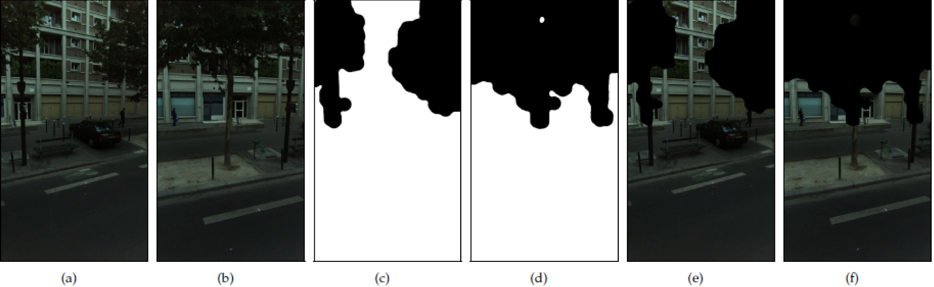
Results of the generation of image masks hiding occluding facade objects by fusing detected occluding facade points and multi-view facade images. (a) and (b) are two image samples with projected 3D points. (c) and (d) are associated generated binary masks. (e) and (f) show hidden facade occlusions from the generated masks
A morphological dilation is applied onto each projected point in the binary images for amplifying the covering of occlusions and filling gaps. In particular, the structuring element (i.e., kernel) Kd that is employed for the dilation of the binary images B is a large circular kernel (radius of 50 pixels) that operates onto the totality of the binary image—scattered single points.
For each detected occluding point, the point can be enhanced into a cube by considering a neighboring, i.e. 3D morphological dilation. The aim of this stage consists in intensifying the density of points in order to produce masks (image masks) that cover more the occluding objects (e.g., at occlusion contours). Visually, we can observe that the coverage of facade occlusions can be enhanced. However this technique is very expensive in computational time in the sense that the number of occluding facade points is multiplied in our case by 9 (e.g.; see results in Fig.6).
Detected 3D occluding facade points and additional 3D points resulting from their 3D dilation that are both projected onto a retained oblique facade image.
A morphological erosion is then applied to the dilated images with a small circular Kernel (radius of 20 pixels) in order to reduce the amplified size of the masks at the contours. This step readjusts the masks to the occlusion size. Two examples of the resulting binary masks are shown in Fig.5(c) and Fig.5(d).
Finally, a smoothing is applied to the contours of the masks in order to reduce the visual effect of artificial edges caused by the accumulation of circular Kernel patterns. In this way, the rendering of a mosaicing with facade images by subtracting the masks, i.e. reconstructed textures will be not overly affected at the multiple recovered junctions (see results in Fig.5(e) and Fig.5(f)). Here although the boundaries due to the mask are visible, their appearance is not affected by the kernel's shape. Then, ortho-image of facade images (with masks) are generated. Finally, a raw mosaicing is achieved by overlapping all the processed facade images excluding the masked regions due to occluding objects (Fig. 7(b)).

Results of the recovered occlusion-free quasi-real texture in the case of a strongly occluded facade. (a) shows a wide frontal facade occlusion. (b) shows the reconstructed textures in multi-view. (c) and (d) show top and central facade regions with resynthesised texture in persisting non-visible facade parts. (e) shows recovered facade true colors.
3.3.3 Enhancing rendering of reconstructed textures
As can be seen in Fig.7(b) it happens that the recovered texture is partially incomplete in cases of strong occlusion such as shown in Fig.7(a). In this section, we describe the steps we apply to improve the rendering of this reconstructed texture in order to generate a texture more suitable for visualization. In particular, our interest is essentially focused on remaining occluded texture parts. Inpainting techniques can be semi-manually employed in order to process a subset of textures in cases of extreme occlusion. Notably, techniques such as resynthesizing can be directly applied for the removal of remaining external objects in major critical parts of the reconstructed facade texture. Here, we have used GIMP (GNU Image Manipulation Program) with the Resynthesizer plug-in developed as a part of [17]. This operation requires delineating targeted regions and filling them by using a powerful transfer method based on the remaining surrounding texture. This practical method is a variant of the best-fit methods described in [18] and [19]. Results of resynthesizing are illustrated in Fig.7(c) and Fig.7(d). Moreover, Fig.7(d) presents an unnatural green color tone due to ill-tuned white balances of the cameras or variation of scene illumination during the acquisition. Fig.7(e) shows a result of global adjustment of the color levels by applying an Automatic White Balance (AWB) functionality of GIMP onto the resynthesized texture. Facade true colors are recovered with success. This functionality can also be applied manually by picking master colors. We point out the fact that these semi-manual stages represent minimal interventions and the texture finally produced is quasi-real. Furthermore, we have currently avoided rendering improvements based on the image blurring or image blending in real facade texture parts in spite of remaining imperfections. Indeed, our interest lies in the preservation of the radiometric richness for pixel intensities located in the recovered real facade texture regions (e.g., for image-based post-computations or for zooming).
4. Conclusion and Future Works
Facade clusters and quadrilaterals are extracted by fusing a selected cadastral map (facade initialization, global coherence, residential limits, semantic) and laser data (high accuracy, dense sampling). Facade occluding points (detected from the estimated quadrilaterals) are projected onto the associated multi-view images. Occlusion-free facade textures are reconstructed from image masks exploiting fundamental image processing techniques. Aesthetic quality of the produced final textures is enhanced in case of strong occlusions or missing facade regions by using some semi-manual restorations. The obtained results rely on a synergistic use of real urban street laser data, optical images and an existing 2D building map. The proposed technique is able to substantially improve the visualization and the computational modeling.
In particular, since the produced facade maps are georeferenced and retextured without occlusions, this information provides uniform and compatible registration and positioning features for the research in vision-based navigation and localization of street robots along the sidewalks for processed areas. At term, we emphasize that the wide-scale urban facade maps generated from data collected by mapping vehicle sensors could be used for fostering the navigation of street robots; and inversely, the detailed data collected by street robot sensors could be used for completing and extending the wide-scale urban maps with local information.
More expressly, future work will be to vectorize the accumulation map by using image processing algorithms for producing generic facade maps. We also intend to improve the mask geometry (occlusion covering) and radiometry (local equalization) as well as to optimize the number of images used in the mosaicing. Notably, the occlusion covering can be enhanced by using oblique or rotatory sensors. This can also be done by initializing region growing approaches from the facade foreground hyper-points. We also intend to apply mosaicing algorithms (e.g., [20]) to improve the inter-patch alignment and the overall photo-realism of the output as well as automating stages for texture inpainting.
Footnotes
5. Acknowledgements
This work was funded by “Institut national de l'information géographique et forestière” (France) and by a Strategic Research Cluster grant (07/SRC/I1168) by Science Foundation Ireland under the National Development Plan. This work was also supported in part by the Spanish Government under the project TIN2010-18856. The authors gratefully acknowledge these supports.