
Abstract
This paper describes a desktop-mechatronic interface that has been conceived to support designers in the evaluation of aesthetic virtual shapes. This device allows a continuous and smooth free hand contact interaction on a real and developable plastic tape actuated by a servo-controlled mechanism. The objective in designing this device is to reproduce a virtual surface with a consistent physical rendering well adapted to designers' needs. The desktop-mechatronic interface consists in a servo-actuated plastic strip that has been devised and implemented using seven interpolation points. In fact, by using the MEC (Minimal Energy Curve) Spline approach, a developable real surface is rendered taking into account the CAD geometry of the virtual shapes. In this paper, we describe the working principles of the interface by using both absolute and relative approaches to control the position on each single control point on the MEC spline. Then, we describe the methodology that has been implemented, passing from the CAD geometry, linked to VisualNastran in order to maintain the parametric properties of the virtual shape. Then, we present the co-simulation between VisualNastran and MATLAB/Simulink used for achieving this goal and controlling the system and finally, we present the results of the subsequent testing session specifically carried out to evaluate the accuracy and the effectiveness of the mechatronic device.
1. Introduction
The mechatronic interface has been developed within the context of a research project, aiming at studying a system to render shapes of industrial products (i.e., cars, domestic appliances) through the use of haptic interfaces. The final objective of the research is to develop and experiment with novel interaction concepts and metaphors for product design that allow designers and stylists to handle digital shapes in a more intuitive and easy manners, while preserving their natural manual skills and not limiting their creativity. In order to create virtual shapes with aesthetic value, designers commonly use Computer Aided Design (CAD) tools. These tools allow them to draft either part or all of the product before building the actual physical model. This practice allows the designer to fine tune the product shape while it is still at the draft stage. In the CAD approach currently widely employed, there are important limitations regarding the interaction between the virtual model and the designer. Firstly, although designers often work on three-dimensional (3-D) models, the systems they use are mostly limited to 2-D displays. Secondly, the designer is not able to evaluate and manipulate the object using a hands-on intuitive approach; the designer cannot touch and feel the object, but interaction is limited to a traditional computer keyboard and pointing devices. During the development of new concept products, designers need to physically interact with the evolving shapes of the product they are designing so as to check and evaluate aesthetic features of the product. The satisfaction of this need requires the production of physical prototypes. In this paper, we describe a mechatronic device consisting of a servo-controlled physical strip, which aims to represent a step forward in the field of digital surfaces exploration. Such a device allows a continuous, free hand contact on a developable plastic tape actuated by a servo-controlled mechanism. The mechatronic interface allows designers to evaluate the aesthetic quality of a product, thus providing a consistent physical rendering of its surface. In addition, the mechatronic interface allows the possibility on the one hand of evaluating early on in the design process components that do not already exist, and on the other hand, of feeling components through physical interaction. This practice can be effectively used for rapid design evaluation and review of new products. The major benefit would be the reduction of the time required for the production of physical prototypes, and therefore, the reduction of the total time to market, without affecting the quality of the final product.
2. Related Works
At the KAEMaRT group, we have been developing haptic devices to permit touch interactions between human users and virtual objects. All the previous mechatronic devices related to the haptic strip have been developed in the context of the Sound And Tangible Interfaces for Novel product project (SATIN project) [1]. The haptic interfaces, described in detail in our previous work, consist of a flexible strip that is held in space in front of the users using two HapticMaster systems [2]. This set-up allows for six degrees of freedom in the movement of the haptic strip. The strip consist of a series of nine equidistant relative actuators, which allow it to actively shape itself in order to match the curve of the virtual object along a geodesic curve. The haptic interface is inspired by the deformable tape that designers use for creating and modifying aesthetic shapes. The haptic strip is based on a modular architecture of elements that deform a plastic tape. Most of the research and development activities on haptics have concentrated on point-based force-feedback devices. Some of the most relevant force-feedback technologies are the following [3]: point-based devices like the PHANToM [4], the MOOG-HapticMaster [5] and the Haption-Virtuose [6], and multipoint-based devices like the Haptex [7] system, and the T'nD system [8]. Some interesting research works are mainly based on vertical pins displacement for midscale virtual surfaces [9], or more recently, on a miniature pin array tactile module [10] based on elastic and electromagnetic force for mobile devices, which provides enough working frequency, output force and amplitude to stimulate the human's mechanoreceptors. A small and lightweight tactile display described in [11] is integrated into a haptic glove system. In [12], a tactile display using airborne ultrasound is presented: the prototype presented provides a weak force for users to feel constant pressure, just sufficient for vibratory sensation. In [13], the authors present a haptic interface capable of simulating the forces experienced during abdominal palpation using pneumatic actuators. In [14], a continuous tangible user interface for modelling free form 3-D objects is described, such as landscape models by scanning and illuminating a Clay or a SandScape; nevertheless the actual system does not provide force feedback. There are several studies which utilize the Immersion CyberGlove [15] whose main draw back is that it is quite invasive because the user needs to wear a glove covered by an armature. To overcome some drawbacks of conventional systems related to the use of point-based force-feedback, tactile and glove devices, we have designed a pleliminar version of the haptic strip [16] with the main objective of just integrating the various mechanical components in order to validate the concept at the basis of the strip, which is related to the cutting plane metaphor. The designer selects a cutting plane on the virtual object, and the haptic strip conforms to the curve computed by intersecting the cutting plane with the virtual object. Subsequently, a higher performing version of the haptic strip [17], [18] has been designed, with the aim of extending the domain of curves that can be haptically rendered: the second strip is capable of rendering geodesic trajectories in addition to planar ones. The mechanical configuration of both releases of the strip achieves a minimum-bending radius of 180 mm, which directly limits the total curves that the haptic strip is able to represent. Obviously, the smaller the bending radius of the haptic strip, the higher the domain of virtual shapes that is possible to render. In both configurations of the haptic strip (planar and geodesic), the device is able to reproduce curves that lie on the virtual object. In [19], we developed the concept of reproducing a real surface using the tessellation approach by using the TRIZ methodology [20] for reducing the volume and the weight of the device to meet more demanding industrial applications. The SATIN system set-up in its entirety is not portable, and owing to its relative expensive set of components, only one prototype has been built. The main idea in the design and construction of the mechatronic device described in this paper consists of upgrading the concept demonstrated in the SATIN system by using a desktop and portable mechatronic device.
3. The cutting plane and Minimal Energy Curve (MEC) spline approaches
In the mechatronic device presented in this paper, although dealing with 3-D models, the haptic interaction is provided through a 2-D cross sectional slice of the virtual object's surface, which we refer to as the cutting plane.
3.1 Cutting plane metaphor
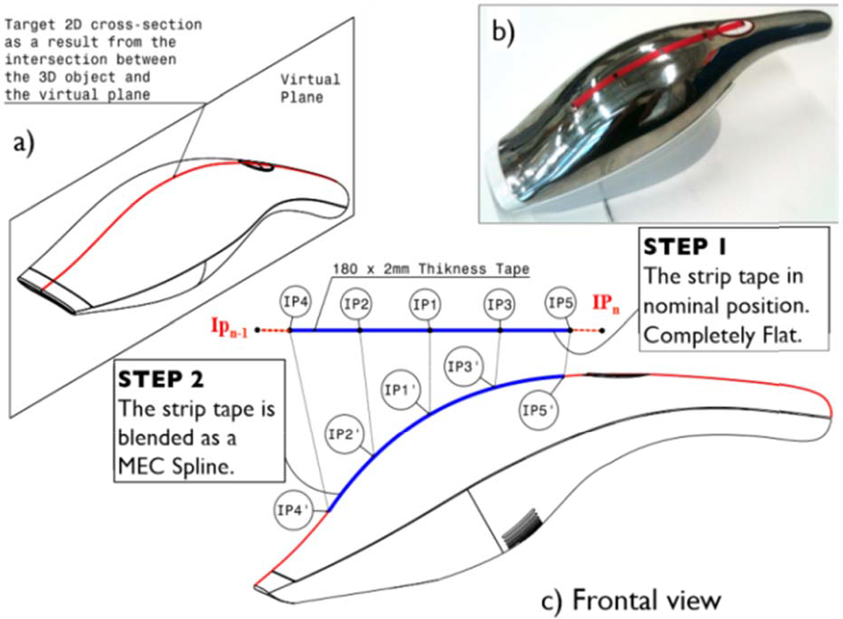
The basic concept is to use a virtual cutting plane as a 2-D interaction tool with the virtual object. In the intersection of the virtual cutting plane with the virtual object there is a 2-D cross-section slice as can be seen in Figure 1-a. Figure 1-b shows the real vacuum cleaner and the tape attached on its surface mimicking this approach. A portion of this 2-D cross-section slice is the target curve on which the tape will be located. The physical strip represented by the blue line on Figure 1-c is blended as a MEC spline in which several interpolation points have been used. This section, provides an analysis related to the number of interpolation points required in order to acquire the best performing shape for the physical rendering of the target curve.
Cutting plane and MEC spline approaches
As a shape exploration tool, the haptic strip represents one of the very few attempts at a full, whole hand shape display. Being a haptic device, the tangible strip is an output device in which the strip is an exploration device for the human hand and fingers to touch. The haptic strip is implemented by means of a continuous physical surface that is actuated into the desired shapes by actuators along its length.
3.2 The MEC spline interpolation approach
In order to better approximate the virtual 2-D cross-section with the real tape, we decided to use the Minimal Energy Curve (MEC) spline interpolation approach to control the mechatronic device. This approach simplifies the conformation of the developable real strip on the virtual one. In practice, the physical tape is able to approximate the shape of the virtual object's surface by adopting the shape of a MEC spline, which passes through a set of several interpolation points. The main idea behind the MEC spline interpolation is based on the designer's tool used to draw several, smooth curves through a number of points. ‘Smoothest’ refers to the equilibrium, or minimum-energy configuration, of an ideal elastic beam constrained to pass through the control points. Our mechatronic device in fact assumes this approach, in which the flexible tape is bent across each of these interpolation points, resulting in a pleasingly smooth curve. The mechanical spline is the basis for essentially all the works related to splines. In fact, the word spline originally refers to a thin strip of wood used to interpolate control points.
3.2.1 Some properties of MEC splines
The physical tape that is used in our mechatronic device uses a real strip (the mechanical spline concept). Its mathematical idealization is the Minimum Energy Curve (MEC), and the curve describing segments between adjacent control points is the elastica, and the tangents are chosen so that G2 continuity is preserved across each control point. In other words, it is an elastica passing through a sequence of constraints, each of which rotates freely and allows the elastica to slide freely through it.
3.3 Porcupine curvature analysis considering the MEC spline approach
A porcupine curvature analysis has been performed taking as geometry references, both convex and concave arc segments. The porcupine plot is a visual curvature analysis technique for curves and surfaces, which places visual ‘quills' at points along a curve. The Frenet frame of the curve determines the direction that the quill displays at that point on the curve, while the relative length of the quill reflects the curvature and/or the radius at that point. The greater the curvature of the curve at the quill point, the longer the length of the quill. The porcupine analysis has been done with a parameter of density equal to 30. With this parameter, the curve has been segmented in various equally spaced segments. Five different radii have been used in this analysis (80, 100, 120, 140 and 160 mm) in order to render a convex and a concave shape with the same radius. For each single radius value, the interpolation point distance has been modified from 45 mm to 25 mm. These distances have been assigned while the strip is in nominal position (completely flat). In total, for each curve we have measured the radius curvature value for the 30 points. We decided to perform several analysis, also changing the number of interpolation points in which the tape is bent, firstly by using three interpolation points, then the strip is bent using five and seven interpolation points, respectively. Figure 2 shows the error in terms of curvature radius (mm) in which three interpolation points have been used to bend the spline. According to the results, the error is really high at the extremities of the strip.

Fitting convex and concave shapes through three interpolations points (Error).
For three control points placed in an equilateral triangle with the spline passing through them, and using the same control points in order to create a circle, the containing radius for the spline is approximately 1.035 times the radius of the circle going through the control points. With four points, this radius deviation decreases to about 1.009, and asymptotically converges as O(n4) with the number of points.
The errors reported on Figure 3 are related to the porcupine analysis in which the concave and convex shapes have been rendered through five interpolation points instead of three.

Fitting convex and concave shapes through five interpolations points (Error).
This is the ‘ideal’ zone in which the mechatronic device should bend the physical strip in order to reduce the fitting error in terms of curvature radius. In this case, the highest error value is presented on the extremities. In fact, the error variation comes down from 13.99 mm to 4.34 mm, having 45 and 25 mm respectively in the distance between the interpolation points.
Figure 4 reports the error related to the porcupine analysis in which the concave and convex shapes have been rendered through seven interpolation points instead of five. It also shows the ‘ideal zone’ in this setup while fitting the shapes.
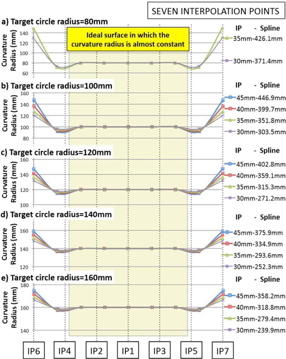
Fitting convex and concave shapes through seven interpolations points (Error).
By comparing the errors reported on Figures 2, 3 and 4, we can conclude that the number of IPs and the distance between them have an important influence factor on the curvature radius error on the extremities of the spline. A second conclusion based on this analysis suggests the use of at least seven interpolation points in order to have an ‘ideal zone’ of curve representation. Having five interpolation points instead of seven reduces the number of servo motors required to bend the physical strip, e.g., if seven IPs are used for the spline, six servo motors will be required to bend the strip, conversely, if five IPs are used for the spline, only four servo motors will be required.
4. Flexible model simulation
This section first introduces the basic theoretical background using FEM analysis with Nastran, and then describes the procedure for obtaining the modal frequency response required for building and simulating a flexible model of the strip. This modal frequency response analysis includes several materials, for example: aluminium, steel and copper. In addition, we decide to modify the thickness using 1, 2 and 5 mm in the strip. The results are then used in ADAMS-Flex in order to obtain the forces required to bend the strip as a flexible element rather than a rigid body element. The maximal force results will be used as reference for selecting the actuators required for bending the strip.
4.1 Theoretical background
Once the bulk data file has been created (*.bdf), Nastran assembles the system mass and stiffness matrices [21], leading to a set of differential equations, displayed by eq. (1), already transformed in the frequency domain in which the damping is neglected at first. With the separation approach a modal transformation is performed, which diagonalizes the system using the orthogonality properties of the eigenvectors in the modal matrix.

Secondly, Nastran solves the characteristic equations eq. (2) for eigenvalues and computes the corresponding eigenmodes.

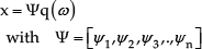
With the separation approach in eq. (3), a modal transformation is performed, which diagonalizes the system from eq. (1), using the orthogonality properties of the eigenvectors in the modal matrix Ψ, consisting of the calculated eigenvectors.
Hereby the system, consisting of N degrees of freedom, is decoupled, leading to a system of N single-mass oscillators, with each oscillator representing an eigenmode of the system in general coordinates qi. (Eq. (4)).

Here, mi is the modal mass, ki the modal stiffness and pi = ψit*f the modal force. With the eigenfrequencies ωi2 = ki/mi, eq. (4) can be transformed to eq. (5). Furthermore, damping can be introduced by a model-damping ratio ςi (eq.(6)).


The solution of this differential equation is well known and using Nastran it is possible to solve.
4.2 MSC. Patran pre- and post-processing with Nastran as solver
In this case, a simple model of the strip is used. In the pre-processing step the model geometry, the finite element mesh, the loads and boundary conditions have been generated. Then, with this data, MSC-Patran automatically creates the MSC-Nastran bulk data file. The geometry used is a single 180×5 mm surface in which an isometric mesh with a global edge-length is 1 mm. This value generates 900 quad elements in the mesh. As in the physical prototype, the central section of the strip is blocked allowing only rotation. Figure 5 shows the results of the modal frequency response analysis. Each material already has four columns, the first indicates the number of the modal frequency, the second column indicates the frequency value for 1 mm of thickness, the third column indicates the frequency value for 2 mm of thickness and so on.

Modal analysis results for different thickness and material.
Figure 6 shows the modal frequency response for the aluminium strip with 2 mm of thickness as reported in Figure 5.

Modal frequency response analysis results (16 different For the bending analysis we only require modes 1, 2, 5, 6, 7, 8, 12 and 13. The rest of the modes are disabled for a fast force computation in ADAMS/Flex.
4.3 Force analysis using Adams/Flex
The force analysis has been performed based on the strip mode synthesis methodology. The strip modal basis is constructed from a blend of normal and static correction modes in order to capture the strip's dynamic response. The modal basis can be easily modified by disabling individual modes, which do not significantly contribute to the strip's motion. The Modal Neutral File (MNF) contains the description of the strip's flexibility for MSC.ADAMS; once the MNF file has been created, the FE application is no longer needed. The MNF completely encapsulates the data transfer from the FE application to MSC.ADAMS, allowing a complete interaction between finite element and multi-body dynamic analysis. Figure 7 shows the procedure and the results of the force analysis in order to reach the target radius. Firstly, the strip has been blended through forces applied on interpolation points 2 and 3 (first step), the force is applied normal to the strip. Then, the strip is blended using all the interpolation points as can be seen from Figure 7-b. Figure 7-c shows the isometric views of the strip in nominal and final positions respectively. The forces reported on the right of Figure 7 in which the strip's thickness has been modified from 1 to 5 mm show a low force value required to bend the strip with 1 mm of thickness.
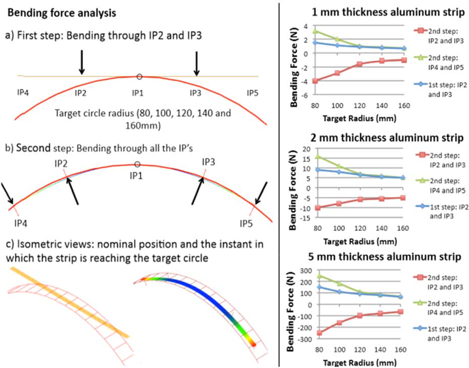
Bending force analysis.
These forces have been used to select the actuators. In fact, the servo drives have been selected so as to guarantee high reliability: the servo motor with titanium gears provides up to 2.35 Nm of continuous torque. The servo drives are HS-5955TG manufactured by HITEC [22]. This allows us to get high stiffness and load capacity.
5. Transmission system
The primary considerations in transmission design concern stiffness, efficiency and cost. Several transmission systems have been analysed in the design of our device; a combination of absolute and relative actuation seems the most suited transmission systems to be used by actuating the mechatronic device.
5.1 Combined transmission system
The purpose of a transmission or drive mechanism is to transfer mechanical power from a source to a load. Combining the absolute with relative actuation requires a unique virtual interaction model. The position of the interpolation points changes based on the geometry of the virtual object. The interpolation points need to be correctly positioned while in contact with the virtual surface. The algorithm that drives this continual computation of contact location is based on the control of the seven interpolation points using the MEC spline approach. Figure 8 shows the concept of the transmission system of the device; Figure 8-a shows the event in which a concave surface is performed.

Mechanism used to actuate the desktop haptic interface.
Note: in the kinematic diagram we use the absolute and relative approaches on the servo actuators' array. Figure 8-b shows the mechatronic device in nominal position and Figure 8-c shows the event in which a convex surface is reached. As required for the MEC spline approach, the device guarantees not only rotation, but also provides a slot constraint in order to allow a free conformation by the strip while reaching the virtual shapes. In other words, the strip is passing through a sequence of constraints, each of which rotates freely and allows the strip to slide freely through it. Note: the spline segments between the interpolation points are not equally separated while reaching the virtual shapes. The interpolation point 1 (IP1) is linked to the ground through a revolute joint constraint. Actuators 2 and 3 (A2 and A3) are also fixed to the ground allowing the absolute approach in the transmission system. A2 through the proposed array of elements is responsible for rotating (while α2 rotates) the IP2 and then A4 is linked to A2 allowing the relative transmission required to locate IP4 through α4 and so on. We have performed several simulations with MSC. VisualNastran 4D in order to test the influence of different parameters in the curvature radius of the final spline. These parameters are directly related to the best fitting of the ideal curve, the number of interpolation points and the distance between them.
5.2 Control of the desktop mechatronic interface
The device is controlled by a co-simulation between the multi-body model, which simulates the kinematics and computes the actuation angle for the servos in MSC. VisualNastran 4D, and Matlab/Simulink, which processes the angles further in order to drive the servos. We decided to use the independent-joint control strategy (i.e., decentralized control), which means that the control inputs of each servo motor only depend on the measurement of the corresponding joint orientation on the mechatronic device as shown in Figure 9.
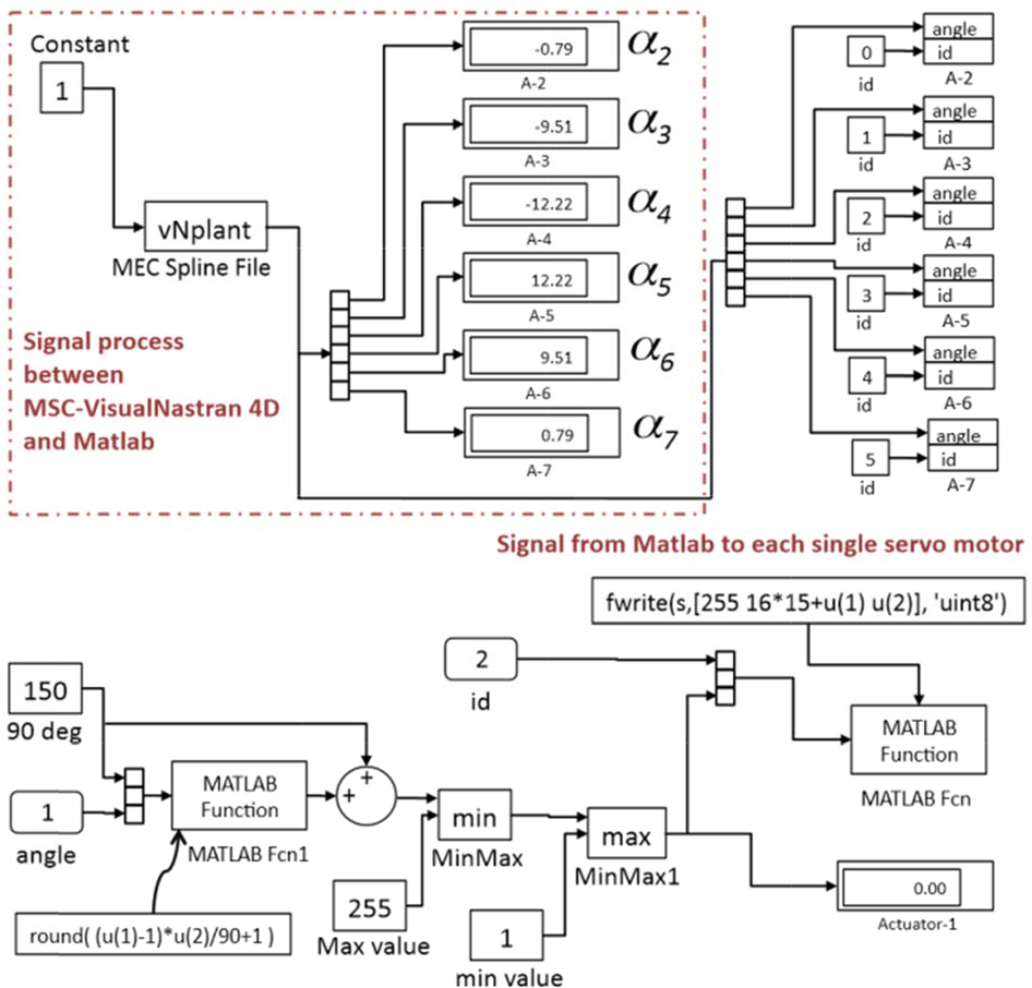
Control scheme through MSC-VN4D and Matlab.
Due to its simple structure, this kind of control scheme offers many advantages. For example, by using independent-joint control, communication among different joints is saved. The simplest independent-joint control strategy is used to control each joint axis as a single-input single-output (SISO) system. The communication between Simulink and vN4D is done with a special block named vNPlant. In this scheme, α is the angular variable of the servo motor that is computed inside MSC. VisualNastran 4D, then through Matlab, each angular value is processed and sent to the servo motors. For each single interpolation point an α angle is required. The α angle required by the servo motor is exactly the same α angle computed while the strip takes the shape of the virtual object. We decided to include bending moments through side forces on each module using single push rods. The mechatronic device requires the combination of seven interpolation points to reproduce both convex or concave and a combination of surfaces. The shapes that can be made exactly with the developable strip driven by side force actuators have been analysed.
As can be seen from Figure 9, the haptic strip has six degrees of freedom, e.g., six cylindrical constrains which are controlled by six servo motors in real time.
6. Use of the desktop mechatronic device
This section describes the use of the mechatronic device. Once the virtual surface is reached, the user is able to feel the shape of the virtual object using the dominant hand. This operation is performed in the same way as in the real world when using both hands.
6.1 CAD integration and associativity
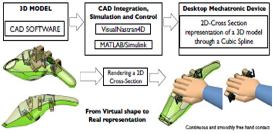
As mentioned in the previous section, the core of this system is the combination of vN4D and Mathworks' Matlab/Simulink packages, which are used to control the whole system and to display the visual interface for the user through a computer screen. These sets of software tools provide the user with an efficient approach for designing test, measurement and control systems. It can also be seamlessly connected to equipment such as the DMX Servo-12 controller board that is used as the interface between the computer and the servo actuators. This system uses a computer to act as the control module and the display module. The mechatronic device performs as the human interface module, through which people can feel the corresponding virtual developable surface. Figure 10 shows the concept-scheme for our approach. The 3-D model step is represented on the left, in which the user models the 3-D object by means of using any commercial software (Autodesk Inventor, Pro/Engineer, Solid Edge, SolidWorks, etc.), then the model is directly imported into Vn4D. This link between the CAD software with Vn4D allows the possibility of maintaining the parametric constraints assigned by the user in the creation of the 3-D model. If a modification is required, the user is able to perform the change in the CAD software. This modification is automatically incorporated into the Vn4D motion simulation.
Mechanism used to actuate the desktop haptic interface.
The central column on Figure 10 shows the CAD integration and associativity, in which the dynamic modelling with Vn4D is extended to include control with the integration of Simulink. Vn4D is used to construct the dynamic model, while Simulink is used to design the control system. A Vn4D library is inserted as a block (vNPlant) into the Simulink model, allowing feedback between the control system and the dynamic model. Finally, the right column shows the integration with the desktop mechatronic device, whose main objective is to reproduce a 2-D cross-section of a 3-D model, allowing a continuous and smooth free hand contact.
7. Real prototype and its limits
The real prototype has been manufactured taking into account some considerations related to the use of sheet metal components that implies: low inertia, lightweight parts and low friction. For the haptic strip a critical concern is the component stiffness while reaching the target surface. Because the seven joint shafts are torque-transmitting members, they and their supporting structure and the sheet metal components have been designed both for bending and torsional stiffness. In addition, the mounting arrangement of the set of actuators' housing has to be designed to accommodate manufacturing tolerances. Figure 11-a shows the frontal view of the prototype of the desktop haptic interface with the absolute and relative actuators.

Prototype of the desktop haptic interface.
Figure 11-b shows the event in which the plastic tape is in nominal position. This configuration has been considered in order to prevent collision between the components. Figure 11-c shows the desktop haptic interface prototype while reaching a concave shape and Figure 11-d shows the event in which the strip renders a convex shape.
7.1 Accuracy validation while bending
In order to determine the accuracy of the desktop strip, we have compared the real strip and the virtual 2- D cross-section slices. Several measurements have been performed using the Konica Minolta 3-D scanner [23] device as can be seen from Figure 12. The Konica Minolta 3-D scanner has an accuracy of 50 μm enabling 3- D measurements. Figure 12-a shows the strip and the Konica Minolta while scanning. Figure 12-b shows the Minolta screen while capturing the data of the strip. Then, Figure 12-c shows the geometrical elements resulting from the scanning process. These data have been exported into STL format in order to compare with the CAD surfaces. We have measured the error in the spline segment from the IP1 to the IP3 as can be seen from the detailed view. In fact, there is an evident error between the 2-D cross-section curves with this segment of the spline. We have also measured the error considering the physical strip. Figure 12-d shows the event in which the actuators provide the rotation required in order to bend the strip for reaching a concave shape. In addition, in this simulation the error between the physical strip and the 2-D target curve has been measured. While the strip reaches the concave virtual surface, there is a relative movement between the servo actuators located at the extremities and the servo actuators located at the centre.

Measurement process (Konica Minolta 3-D scanner).
Similar analysis has been performed while the strip reaches a convex shape as can be seen from Figure 12-e. Firstly, the physical strip has been bent through the interpolation points 2 and 3 (IP2 and IP3), then the error has been measured between the physical strip and the ideal curve only between the IP1 and IP3 segments, and finally, the relative actuators have provided the rotation in order to render the final concave shape. The measurement results and the comparative errors are reported on Figure 13. As explained in the previous section, several radii have been analysed(80, 100, 120, 140 and 160 mm) for the events in which the strip renders a convex and a concave surface. The results report the data in terms of the distance from the ideal circle to the curve rendered by the physical strip considering the radial distance. We have measured these distances with a delta angular pattern of 2.62 degrees. Figure 13-a shows the results in terms of millimetres for the error in the shape rendering. The first column shows the results for the event in which the virtual strip is bent only by the IP2 and IP3 without moving the relative actuators linked to the IP4, P5, IP6 and IP7. The second column shows the results considering the physical strip. These results report the error from the IP1 to the IP7 spline segment. Note: the positional error is quite small and the worst case is about 1 mm. The third column reports the error in terms of millimetres between the physical strip and the ideal curve in which all the interpolation points have been positioned by the actuators in order to lie on the virtual object. However, the physical strip does not correctly fit the virtual shape, and in this case, the average error is about 2 mm. The same experiment has been done for the concave shape and for the rest of the radius. Note: the higher discrepancy between the real strip and the 2-D cross-section relies on the interpolation points located at the extremities.

Positional errors reported while bending.
This is most probably because with the physical strip is not possible to control the tangency in the extremities. However, the errors are quite consistent and the worst case reports an average of 2 mm.
7.2 Porcupine curvature analysis in the physical strip
A porcupine curvature analysis has been performed taking as geometry reference the measured curves of the physical strip. This analysis has been performed considering the physical strip while reaching the virtual convex and concave shapes in order to know the accuracy of the device. The porcupine analysis has been done with Similar results are reported in Figure 14-b, Figure 14-c and Figure 14-d. These results report the error from the IP1 to the IP7 spline segment. Note: the positional error is quite small and the worst case is about 2 mm.

Positional errors reported while bending.
8. Case study
This section presents the evaluation of the mechatronic device whose aim is to reach rigorous, valid and practical conclusions about the accuracy of the device compared with a real product. In our research we have been interested in two main areas. The first was to evaluate the mechatronic device in terms of accuracy while representing a 2-D cross-section; the second was to re-design the device and provide some different approaches for the design of future devices by using the evaluation results. Figure 15 shows the experimental setup for the evaluation and comparison with a real product (a vacuum cleaner designed by the Alessi company). Three different 2-D cross-sections on the vacuum cleaner have been rendered and measured with the 3-D scanner in order to ascertain the accuracy error in terms of millimetres. Figure 15-a shows the location of the first 2-D cross-section, then the real vacuum cleaner and the user's hand while touching the 2-D cross-section and finally the mechatronic device and the VisualNastran interface which is rendering the 2-D cross-section.

Experimental setup.
Figure 15-b shows the second 2-D cross-section, which is located at the middle part of the vacuum cleaner, then the real vacuum cleaner and the mechatronic device takes the shape of the virtual object. The same procedure is displayed in Figure 15-c in which the third 2-D cross-section is located at the back of the vacuum cleaner. Figure 16 shows in detail the three different 2-D cross-sections that have been rendered. We also show the error variable, according with the minimal distance between the position of each interpolation point that lies on the real strip and the curve of the virtual object.

Position of the DHI in the comparison with the real product.
Figure 17-a shows both, the strip while reaching the target curve and the curve which represents the real product. Figure 17-b shows the results comparing the measured curves on the left side of the vacuum cleaner, then Figure 17-b shows the results comparing the curves on the middle and Figure 17-c shows the results in which the curves are compared considering the right side position. The simulation and the measurements are quite close. Note: the higher discrepancy between the real strip and the 2-D cross-section relies on the interpolation points located at the extremities.
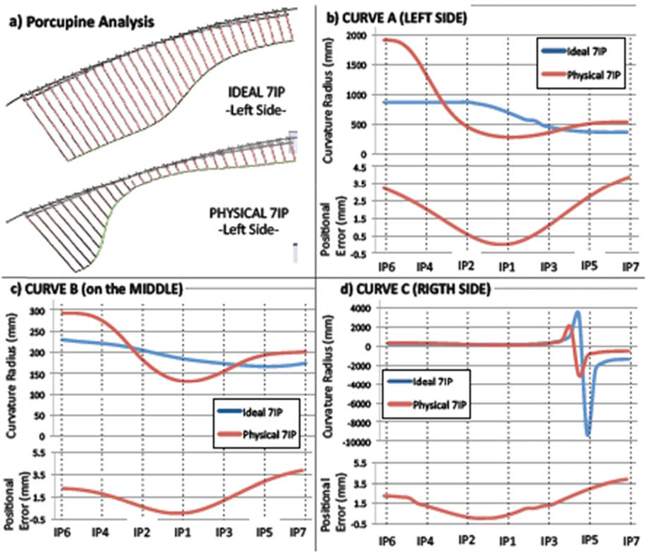
Vacuum cleaner results.
The error reported on the extremities of the DHI is higher than in the central part. On the extremities the ideal shape is not reached by the DHI, because is not possible to control the tangency on the interpolation points located at the extremities (IP6 and IP7).
8.1 Rapid prototyping and the mechatronic-interface
Rapid prototyping is a broad term for a variety of manufacturing procedures that stem from information provided from a 3-D computer model. Rapid prototyping includes into several methodologies separated by production techniques and processes. Layer manufacturing, stereo lithography, selective laser sintering, fuse deposition modellers, 3-D printing, and Computer Numerical Control (CNC) machining are the most common processes. The technical differences between these methods will not be discussed here. It should be noted that the usage of the term ‘rapid’ may be a misrepresentation as the process can take hours to days of processing time [24] depending on the size and shape of the product. Although physical prototypes are a good means for product evaluation, they also add some limitations; for example, they do not allow variants of shape and material, and they do not support easy shape modification and immediate correlation with the corresponding digital model. In addition, the production of the physical prototype is costly and time consuming, especially with respect to the other product design phases. The mechatronic-interface offers an immediate physical feedback about the virtual shape allowing the possibility on the one hand of evaluating early on in the design process components that do not already exist, and on the other hand, of feeling components through physical interaction. This practice can be effectively used for rapid design evaluation and review of new products. The major benefit would be the reduction of the time required for the production of physical prototypes.
9. Conclusion
In this paper we have presented a successful method to physically render a 2-D cross-section of a virtual object. The paper proposes a novel mechatronic device based on the Minimal Energy Curve (MEC) spline approach. The device allows a continuous and smooth free hand contact on a developable real plastic tape actuated by a servo-controlled mechanism. The objective in designing this device is to reproduce part of a cross-sectional contour or curve in 3-D space with a consistent physical rendering process well adapted to designers' needs allowing a continuous and smooth free hand contact interaction on a real and developable metallic strip. The desktop mechatronic system might indeed be useful for designers who are not certain about the end product and can use it for testing out ideas and concepts. We have performed some preliminary tests in order to prove the concept and understand the quality of the representation of an aesthetic surface offered by the desktop mechatronic device. The tests results are good both in the quality of the rendering of the surface and in the interaction modality offered.
10. Future work
Future research on the device and its application might be able to point to the role of different methodologies in rendering more complex curves such as, for example, the geodesic curve and the surface-developable techniques.