
Abstract
This paper presents a millimeters scale omni-directional mobile microrobot with special dual-wheel structure. The microrobot was actuated by three electromagnetic micromotors of 2mm diameter. Dynamic analysis of translational and steering movements presented the relationship between the sizes of the dual-wheel structure and the output torque of the micromotor. Genetic algorithm (GA) was employed to optimize the dual-wheel's sizes for reducing the unnecessary torque consumption and improving the driving ability of the microrobot. A computer vision system contained two sets of feedback control is devised for the microrobot. Torque self-balance and current-limiting control approach are presented to ensure the accuracy of step movement. Experiment results demonstrate the feasibility of these concepts.
Introduction
The research of omni-directional robot has received much attention during the past decades, since their omnidirectional structure has more virtues than the common structures.
Omnidirectional robots can be divided into two classes, the special wheel structure and the conventional wheel structure. Special wheels usually have complex structures. K. H. Low and R. L. William developed omnidirectional robots with universal wheels (Low, K. H. & Low, Y. P., 2005; William, R. L., et al, 2002). M. West designed a holonomic omni-directional vehicle with spherical wheels (West, M. & Asada, H., 1992). An omnimobile platform was designed by L. Ferrière using combination of spherical wheel and universal wheel (Ferrière, L., et al, 2001). K. Nagatani developed a robot by four Mecanum wheels for navigation research (Nagatani, K., et al, 2000). Some researches also employed conventional wheels to design omni-directional robots, such as using some kinds of dual-wheel structures. J. Anglees developed an innovative dual-wheel structure with two motors which can achieve three degrees of freedom on a plane (Anglees, J., 2005). T. B. Park developed a mobile robot using three active casters (Park, T., et al, 2002). H. Y. Yu designed an intelligent vehicle for old persons using two active split offset castors (Yu, H. Y., et al, 2004).
The development of mobile microrobots is also a research hotspot. The microrobots have a wide application fields, especially in the narrow space or special environment. P. Dario developed a microrobot with a novel electromagnetic wobble micromotor (Dario, P., et al, 1998). It took part in the international maze competitions several times. M. Takeda developed a chain-type micro-machine for inspecting the outer tube surfaces (Takeda, M., 2001). The Sandia national lab developed an autonomous tractor-microrobot for either civil or military applications (Byrne, R. H., et al, 2001; Siegel, M., 2001). Some research institutes in Europe Union cooperated to design a microrobot system ‘MiniMan’ for micromanipulation (Puig-Vidal, et al, 2001). EPFL developed an autonomous microrobot ‘Alice’ for both scientific and commercial applications (Caprari, G., et al, 2000).
Although much progress has been made in the research on mobile microrobot and omni-directional mobile robot, it is difficult to realize an omni-directional mobile microrobot, especial its size is within one cubic centimeter. In addition to the relatively complicate omnidirectional structure, manufacturing an actuator with higher output and several cubic millimeters volume is also difficult.
This paper presents an omni-directional mobile microrobot with special dual-wheel structure. The microrobot is less than one cubic centimeter, and actuated by 2mm electromagnetic micromotors. The motivation of the research is to design a microrobot that can satisfy the application of conveying micro-parts in a microfactory. Therefore, the driving ability and control are two important issues.
This paper first presents the microrobot structure design, followed by the dynamic analysis, then the GA optimization, and the microrobot control.
Microrobot Design
Structure of Microrobot
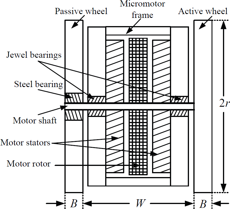
The microrobot consists of two unique dual-wheel structures named active-passive coupling caster (APCC). Each APCC is composed of two coaxial normal wheels which are mounted on both sides of a micromotor shaft, as shown in Fig. 1. The active wheel is joined with the micromotor shaft rigidly, so it is driven by the micromotor directly. The passive wheel is connected with the shaft by a steel rolling bearing, and thus it has the rotary freedom around the motor shaft. This design uses one motor to drive two wheels, and the dual-wheel can either move linearly or rotate around the perpendicular central axis.
APCC structure
The actuators of the microrobot are three electromagnetic micromotors. Two of them are for linear movement, while the other one which is mounted in the middle of the chassis is for steering. The steering power is amplified and transmitted to the APCCs through a set of micro-gears. The 3DMAX model of the microrobot is shown in Fig. 2.

CAD model of microrobot
As the dual-wheel moves forward or backward, the active wheels are driven by the micromotors, while the passive wheels are driven by ground friction. When APCC steers, both the active and the passive wheels are in passive situation, and driven by the steering micromotor. The two APCCs can steer synchronously with the same speed and displacement. Therefore, the microrobot can achieve omnidirectional movement on the plane surface.
The electromagnetic micromotors are manufactured by LIGA technology. They are employed multiple layers planar structure and axial flux, which can reduce the micromotor volume.
The diameter of the micromotor is only 2mm and the weight is 38mg. A permanent magnetic rotor with four pair of magnetic poles is mounted between two stators. Each stator winding is composed of 6 layers, 42 turns and 9 coils, as show in Fig. 3. Its maximum speed and output torque can reach 28000rpm and 4.2 μ Nm respectively. A photograph of a micromotor is shown in Fig. 4.

photo of micromotor stator by SEM
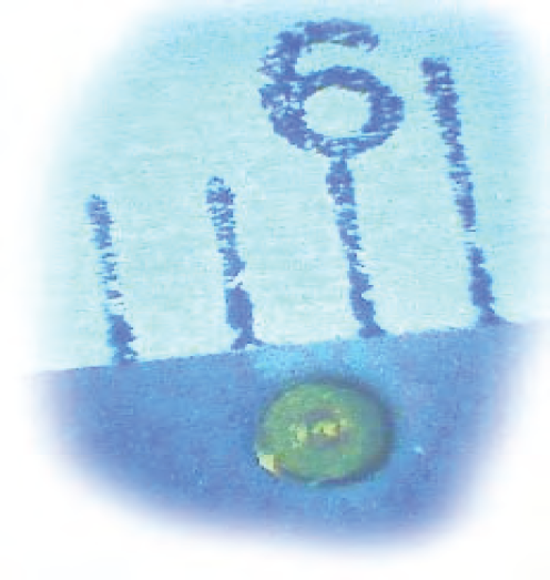
Photo of a micromotor
Since the translation and steering of the microrobot are independent on each other, the dynamic analyses consider the two situations respectively.
Translation Analysis
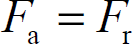
During translation, the two normal wheels of APCC will roll synchronously. They are driven by different modes. As shown in Fig.5 (a), the active wheel rotates around its center driven by the micromotor torque (Md) directly. Meanwhile, the jewel bearings around the micromotor shaft generate the resistance moment (Ms). Since the wheel has a backward movement trend with respect to the ground, a force (Fa) generated by the ground exerts on the active wheel. In fact, Fa is the ground friction, but it is responsible for pushing the active wheel to move forward in this situation. As the active wheel drives the microrobot chassis, it also burdens an anti-force (F1) from the shaft. P is the support force of the ground.

Forces and moments exerted on the dual-wheel during translation
As shown in Fig.5 (b), the passive wheel is connected with the micromotor shaft by a rolling bearing, so it can not be driven by the micromotor directly. It is driven by the horizontal force (F1′) generated by the motor shaft. Since the wheel has a contrary movement trend with respect to the ground, the ground generates the rolling frictional force (F r ). M p is the ground friction moment.
The dynamic equations of the active wheel are presented as:

where m is wheel mass, I is rotational inertia and r is wheel radius.
The dynamic equations of the passive wheel are described as:

Since the active wheel and passive wheel roll synchronously, they have the same movement characteristics (a1 = a2 and


When the wheels move with a constant speed, both the linear acceleration and rotary acceleration will equal zero.
Therefore, according to equation (4), the ground friction moment could be described as:

Moreover, F1 and F1′ are two internal forces which can be eliminated by each other, and thus an expression can be obtained based on equation (5):
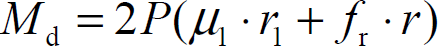
Further, the micromotor torque could be derived form equation (6) as:

Where Ms ≈ 2μ1 · r1 · P, with μ1 is the friction coefficient and r1 is the radius of the jewel bearing; F = f r · P, with f r is rolling friction coefficient of the ground.
Substituting all the relative expressions above for the arguments in equation (9), the needed torque for translational movement could be presented as:
Obviously, the torque has direct proportion with the wheel radius.
During steering, the two normal wheels are in passive states, and driven by the steering micromotor through the set of micro-gears.
As shown in Fig. 6, the steering torque (Mt) exerted on the motor shaft drives the two wheels to rotate around the shaft center of point ‘O’ (wheels revolution).

Forces and moments exerted on the dual-wheel during steering (Top view)
Meanwhile two frictions (F1 and F2) will be exerted on the contact interfaces between the ground and the wheels. According to the principle of moment equilibrium, Mt should be balanced with the moments generated by F1 and F2. An integral function showing their relationship could be presented as:
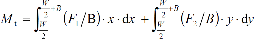
where W is wheels separation, B is wheel width, Δx, Δy are micro sections on the contact interfaces, and x, y are the distances between the shaft center ‘O’ and the micro sections.
Although F1 and F2 resist the wheels revolution, they drive the wheels to rotate around the centers of themselves (wheels rotation).
For the active wheel, moment generated by F1 should be balanced with the resistant moments generated by the ground, the steel bearing and the jewel bearings. The equilibrium equation could be described as:

Where Mr ≈ μ2 · r2 · P is resistant moment of the steel rolling bearing, and μ2 is the friction coefficient, r2 is bearing radius.
For the passive wheel, the equilibrium equation could be presented as:

Substituting the equations (12) and (13) for the parameters (F1 and F2) in function (11), the torque for steering could be derived as follow after integral:
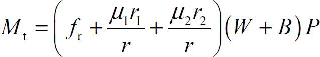
By this equation, the torque has direct proportion with the wheels separation and wheel width, but has inverse proportion with the wheel radius. Although increasing the wheel radius can reduce the steering torque, it can also increase the translational torque according to equation (10). Therefore, the sizes design of the APCC should consider the both aspects.
As a globally convergent optimization solver, Genetic Algorithm is suitable to deal with the constraint problem like APCC sizes design.
Design Constraint
Besides the constraints contained in the equation (10) and (14), the millimeters size and omni-directional structure of the microrobot also should be considered. As shown in Fig. 7, when the two APCCs steer, the sizes design should satisfy the requirement of avoiding the collision of APCCs at their encounter position.

APCCs encounter position during steering
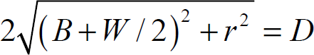
Based on the present level of microfabrication technology and the mechanical principle, the minimum module of the micro-gears is determined as 0.15mm, and the tooth numbers of the micro-gears are designed as 9 and 27 respectively. Thus the center distance of the two big gears D equals 5.40mm (calculated by 0.15mm × (9 + 27)).
To avoid collision, the wheels separation, wheel width, and wheel radius should satisfy the following constraint condition:

By the expressions (10), (14) and (15), the three sizes parameters are constrained by each other. The design target is to minimize the whole torque consumption of the translation and steering by optimizing W, B and r. According the design target, the objective function is devised as:

By adjusting the coefficients Λ and μ, different parameters can be obtained to satisfy different application requirements.
Further, since larger wheels separation and wheel width is benefit to produce a more stable structure, the constrain (15) is changed into an equation to achieve this idea:
And then the wheel radius can be presented as the expression of

The W and B are defined as variables in the GA objective function. The search spaces of each variable in GA which are determined by combing its physical meaning and microfabrication technology are described as (unit: mm):

A genetic algorithm has been developed to design the sizes of the special dual-wheel. The algorithm applies float representation, standard proportional selection, elitism, single point crossover and random uniform mutation. Each parameter can be changed with its domain, the boundaries of which are user specified. The number of generations and population size can be varied according to the computer resource and actual requirements.
In the design of APCC wheel structure for millimeters sized microrobot, the pop-size of generation G is 500, the pop-size of population N is 50, the mutation rate is 0.01 and the crossover rate is 0.5. The action of GA is realized by language C. The process of the algorithm for optimization is shown in Fig.8.

Values of generations in GA design
The search results including the average value of fitness and the best value of fitness are shown in Fig.8. With the increasing of generation number, the population becomes better and better. From the average value curve, there are abnormal populations, such as generations after 200 generations. Through the evolution of population, system can eliminate the bad populations and keep the normal trajectory. This also demonstrates GA can search the best results within global range.
The final results of the dual-wheel's sizes by GA optimization are presented as follow:

These values satisfy the constraint conditions.
The prototype photos of the microrobot are shown Fig. 9. Its whole volume is about 8.5mm × 9.5mm × 9.5mm.

Microrobot photos
Computer Vision System
The microrobot is controlled by a computer vision system composed of a CCD camera, a PC host, a control circuit board, and a platform of simulating pipelines, as shown in Fig. 10.

Microrobot control system based on computer vision
Two feedback control systems are designed for the microrobot control, and their control principles are shown in Fig.11.

Schematic of microrobot control principle
The first feedback system is to realize the basic movement modes control. The image of the microrobot is captured by the CCD camera on the platform ceiling, and then transmitted to the PC host where the recognition, location and motion planning algorithms are running. The control orders are transmitted back to the local control board that connected with the microrobot directly. Then the microrobot executes the relative actions, such as forward, backward, steering etc.
Since position sensors can not be mounted on the millimeters scale microrobot by present technology, it is difficult to ensure the step accuracy and stability by common methods. Moreover, some factors in the workspace, such as payload, resistance and voltage etc, also influence the step accuracy. Therefore, the function of the second feedback system is to improve the step accuracy and stability. Since the microrobot is actuated by the micromotors, the direct control objects are the micromotors. The torque self-balance concept and current-limiting method for the micromotors are the cores of this feedback system.
The electromagnetic micromotor is designed as a 3 phase synchronous motor, with star-connected windings. Therefore, the micromotor can be used as a step motor controlled by three methods, 2–2 phases conducted method (2-2 PCM), 3–3 PCM, and 2–3 PCM.
The torque waveform of the micromotor under 2–2 PCM is shown in Fig.12. The torque curve of each conducted state (e.g. A-B; and it represents that current in windings is from phase A through middle point to phase B) presents a half sinusoid.

Micromotor torque waveform under 2–2 phases conducted approach (Partly drawing. The torque output with self-balance characteristic for step driving is presented with the red dash lines, and the arrows present the phases commuting sequences.)
From the torque waveform, area I contain the maximum and stable torque output compared with area II. However, if area I was used to drive the microrobot, the time of phases commuting is very difficult to be controlled without the help of position sensors.
The torque output in area II is suitable for step driving, because it possesses the torque self-balance characteristic. Every phases commuting process begins with an initial torque of T sin 60° which decreases according to the regulation of sinusoid with the increasing of the angle displacement. Eventually, the rotor of the micromotor stops at the position where the synthetic torque equals zero, i.e. the torque self-balance point. The angle displacement during this period equals the expected values in theory (electrical 60°), and the stop position is just the started point of next phases commuting process.
The balance process may produce several times of vibrations which the amplitude and frequency has relation with the torque values (T), and the simulated results are shown in Fig. 13. Obviously, a proper torque values is benefit for stable step. Furthermore, the actual stop position will be influenced by the damp (payload, resistance etc) which can result in overswing or insufficiency of the step angles. Therefore, the current-limiting method is proposed to control the currents in the micromotor phases which determine the torque output.

Vibrated curves of angle displacement under torque self-balance control (Damp=0.5 μNm)
To realizing current control, two digital adjustable current-limiting resistors are set between the micromotor controllers and the micromotors on the control board (see Fig. 11). The adjustment signals come from the micro control unit (MCU).
The control principle of the second feedback system is based on adaptive control. When the microrobot moves step by step, the vibration situation and step displacement are captured by the vision system, and be compared with the expected value. The deviation is transmitted to the MCU which will adjust the phase currents of the micromotors by sending digital signals to the adjustable resistors. The micromotors ‘training’ process will not be finished until the proper resistor values are found to ensure the step error within the permitted scope. During the adjustment, the elimination of the vibration will be considered firstly, and then the deviation of step displacement.
In a word, the second feedback system is a useful supplement of the first one, which is mainly responsible for training the microrobot to moving better before beginning a task.
Driving Ability Experiment
Since the microrobot is designed for conveying micro-parts in a microfactory, and on the other hand, to validate the optimal design effects of GA methods, the load-carrying and slope-climbing experiments have been done.
The experimental results are shown in Fig.14. The microrobot can convey a payload of 2.7g or climb a slope of 8.5° with the maximum supply voltages of 12V, which satisfy out application requirement.

Microrobot driving ability with different supply voltages
The micromotor is controlled by 2–2 phases conduced method, and needs change 6 steps rotating in electrical 360°, while 24 steps in 360° by mechanical angle. Therefore, the accuracy step displacement of the microrobot should be 0.39mm (calculated by 1.48mm × 2π/24).
The microrobot is trained by the second feedback system based on the torque self-balance and current-limiting method. A CCD camera with microscope lens is used to satisfy the accuracy requirement. The CCD pixel size is 4μm, and its measurement error is less than 0.012mm. By training, the microrobot can move stably with step error about of 0.08mm. This result can be accepted for its function is conveying, not micromanipulation.
Further, to demonstrate the validity of the computer vision control system, an avoiding barriers experiment is designed using the environment of simulating pipelines. There are two microrobots controlled and guided by the vision system in this experiment. They will move from a place outside of the pipeline area, and finally arrive at the target place near the right-down pipeline after avoiding several pipelines on the route. Some scenes of the experimental process are shown in Fig.15.

Microrobot control experiment in the environment of simulating pipelines
Due to the special structure of the microrobot, the translational movement and steering are independent on each other. Further, the microrobot chassis can keep immovability during the wheels steering. Therefore, the movement path is composed of several line segments. The steering points on the path could be set considering the positions of the obstacles before the microrobot starts. For detecting the position and orientation of the microrobot, a white cap which can turn with the wheels synchronously is set on the top of the microrobot contrasting with the black platform. In the scenery captured by the camera, the cap and its direction represent the microrobot and its orientation. The microrobot must stop moving for determining its location by the camera. If the error between the present position of and desired position is not in the permitted scope, the microrobot will adjust its position to satisfy the requirement.
These experiments illustrate the microrobot system can work well, not only the driving ability, but also the control.
The analysis and optimal design of a millimeters scale omni-directional mobile microrobot has been presented. The microrobot is supported by two sets of special dual-wheel structure, and is actuated by three electromagnetic micromotors with 2 mm diameter.
Since the translational and steering movements are independent from each other, the dynamic analyses derive two functions of the special dual-wheel structure's sizes and micromotor output torque separately. The two functions are synthesized in the genetic algorithm that is used to optimize the sizes of the dual-wheel with the aim of improving the driving ability of the microrobot. Since the microrobot can not achieve autonomous movement, it is a proper way to employing the computer vision system to control. The experiments results demonstrate the driving ability of the microrobot, and the validity of the control system.
Footnotes
8.
This work is supported by National Natural Science Foundation of China (Nos.60475037, 10477013), and Specialized Research Fund for the Doctoral Program of Higher Education (No.20060248057).