
Abstract
Dexterous movements performed by the human hand are by far more sophisticated than those achieved by current humanoid robotic hands and systems used to control them. This work aims at providing a contribution in order to overcome this gap by proposing a bio-inspired control architecture that captures two key elements underlying human dexterity. The first is the progressive development of skilful control, often starting from – or involving – cyclic movements, based on trial-and-error learning processes and central pattern generators. The second element is the exploitation of a particular kinematic features of the human hand, i.e. the thumb opposition. The architecture is tested with two simulated robotic hands having different kinematic features and engaged in rotating spheres, cylinders, and cubes of different sizes. The results support the feasibility of the proposed approach and show the potential of the model to allow a better understanding of the control mechanisms and kinematic principles underlying human dexterity and make them transferable to anthropomorphic robotic hands.
Keywords
1. Introduction
The dexterity of hand manipulation is a distinctive feature of human beings that current humanoid robots can barely replicate. In particular, an important aspect that is poorly addressed in the literature concerns the adaptability of manipulation to variable real world situations. Current approaches to humanoid robotic manipulation, indeed, typically rely upon detailed models of the manipulator and the object being manipulated [1]. For robots designed to move in unstructured environments, however, the capability to autonomously manipulate unknown objects is of paramount importance.
This paper addresses the issue of adaptive manipulation in humanoid robotics from a motor developmental perspective. From this perspective, two critical features underlie the development of sophisticated manipulation skills: (a) the adaptive mechanisms supporting learning; (b) the kinematic features of the hand. During motor development, infants perform a number of apparently unstructured movements (i.e. “motor babbling” [2]), which are thought to play a fundamental role in motor development [3]. Most movements produced during early motor babbling are cyclic movements [4] that involve, for example, scratching, waving, petting, wiping, hitting (with or without another object), turning (e.g. to perceive objects from different perspectives), etc. These cyclic movements allow infants to discover the functioning of their own body, the structure of the world and the potential effects of their actions on it [4–7]. Cyclic movements are probably so important because, being repetitive, they allow infants to acquire multiple sample data needed to develop motor skills despite the high noise of early behaviour.
The paper proposes an innovative approach to cyclic manipulation in robotics, which is based on the joint use of hierarchical actor-critic reinforcement learning (RL) and Central Pattern Generators (CPGs). This approach provides the following main contributions to the problem of skillful manipulation in robotics:
A bio-inspired hierarchical neural architecture that allows a robotic hand to autonomously acquire manipulation skills through trial-and-error learning. The choice of CPG parameters is optimized for each manipulated object, based on the results of the rotational trials.
The application of a new CPG model to robotic manipulation, different from the Matsuoka model used in the literature in [20] and [21]. The proposed CPG model allows the independent managing of all parameters and for the decoupling of amplitude and phase displacement. These are fundamental features required in order to enable the neural network to learn CPG parameters and achieve the correct execution of the manipulation task.
In children, the development of manipulation skills involves a gradual transition from random exploratory cyclic movements to functional movements that produce useful effects on the environment. The literature on the development of manipulation skills lacks models and hypotheses with which to investigate the mechanisms that lead to the progressive development of functional cyclic movements. This paper also contributes to build such a model based on a bio-inspired hierarchical neural architecture that allows robotic hands to autonomously acquire manipulation skills through trial-and-error learning. As such, the model represents a valid tool for generating new hypotheses and predictions regarding the development of cyclic manipulation skills in humans.
The neural architecture of the proposed model is grounded on key computational “ingredients”, all biologically inspired. First, the trial-and-error mechanisms driving the learning of the system are implemented with the use of a reinforcement-learning actor-critic model [8]. The structure and functioning of the actor-critic model resemble those of basal ganglia, the brain structures involved in trial-and-error learning and decision making in living organisms [9]. Recently, several studies have shown that reinforcement-learning actor-critic models have desirable computational properties that make them effective in robotic setups similar to those used here (e.g., based on the use of CPGs and other dynamic motor primitives [10–13]). In this work a neural implementation of the actor-critic model is used as it is highly adaptable and suitable for the purposes of this research.
Second, the actor-critic model generates the parameters of Central Pattern Generators (CPGs), which are responsible for producing oscillatory signals when activated accordingly [14, 15]. Neurophysiological evidence in mammals shows how the activation of neural circuits implementing CPGs (located mainly in the spinal cord) generates cyclic motor patterns. CPGs generate cyclic movements by alternating the activation of flexor/extensor muscles, thus supporting behaviours such as locomotion, respiration, swinging and chewing [14–17]. Fingers also exhibit cyclic movement patterns [18, 19] and can be controlled by CPGs. In this work the cyclic movements of upper limbs and hands observed in early infancy are assumed to be generated by CPGs, although this assumption needs more direct empirical support, which is currently lacking in the literature. On the modelling side, however, notwithstanding this empirical knowledge gap, some authors have already proposed models based on CPGs aimed at reproducing the cyclic contact patterns observed in humans engaged in rotating an object [20, 21]. The Matsuoka CPG model in [20] and [21] is used to replicate the contact between each finger and object during rotational tasks, thus focusing on the force exerted in the contact. In contrast to this, the CPG model proposed in this work uses the formulation in [14], suitably modified in order for it to be applied to manipulation tasks. Unlike the Matsuoka CPG model, the model proposed here allows the decoupling of the amplitude and phase displacement. These two parameters can be independently managed in a simpler manner than in the Matsuoka CPG, thus making the learning of the RL neural network more favourable. In fact, here, CPGs are jointly used with Artificial Neural Networks that are responsible for learning CPG parameters. Each neural output is used as a CPG parameter that can be independently modified during the learning process.
Third, the model is based on a hierarchical soft-modular architecture, by analogy with the hierarchical organization of basal ganglia and motor cortex [22, 23, 24]. In particular, the model assumes that trial-and-error processes, analogous to those of basal ganglia, search the parameters of the CPGs, and the neural network encodes and sets them (similarly to motor cortex that modulates spinal cord CPGs [15, 16]). Hierarchical modular systems have often been used to break down or “decompose” complex tasks into multiple simpler sub-tasks. In the field of supervised learning, for example, the hierarchical system proposed in the seminal work [25] automatically breaks down the whole task into sub-tasks using the similarities of the input-output samples to be learned. In the field of reinforcement learning, task “decomposition” has been carried out, for example, based on the sensorimotor requirements of the sub-tasks [26] or on the dynamical properties of the sub-tasks [27]. In this work, the system relies upon a hierarchy to decide which of a set of CPGs with varying complexity can be used to tackle different manipulation tasks. This type of architecture allows the system to autonomously decide the sophistication of the computational resources to use to acquire and perform different manipulation behaviours, based on object features and task complexity (cf. [24, 25]).
Lastly, the model is tested on two simulated anthropomorphic robotic hands interacting with 3D simulated objects: the iCub robot hand [28] and the DLR/HIT hand II [29]. The main distinction between the two robotic hands, asides from their size, concerns the thumb: the iCub hand has an active DOF for the thumb opposition whereas the DLR/HIT hand II has a fixed thumb opposition.
This feature is directly linked to the second goal of the study, namely the investigation of the role that the kinematic features of the hand can play in the development and final motor performance of dexterous hand movements. The analysis of the kinematic structure of the human hand is crucial for the realization of dexterous anthropomorphic robotic hands [28–32]. In this respect, the literature shows how thumb opposition is a peculiar feature of the human hand and plays a central role in human manipulation capabilities [36–37]. Indeed, biomechanical studies show that the thumb is responsible for 50% of hand functions which enable the human hand to perform complex manipulation skills [36].
Despite the fact that the literature on robotic hands proposes a wide variety of configurations and kinematic models of the thumb, only a few systems have thumb opposition as an active DOF [28, 39]. For instance, in the Utah/MIT hand the thumb is mounted directly opposed to the other fingers in a fixed position [38], while the UB hand is characterized by an opposable thumb with four actuated degrees of mobility [39]. In order to investigate these issues within a computational framework, the proposed architecture is tested on the iCub hand and DLR/HIT hand II and a comparative analysis of the performance of the two anthropomorphic robotic hands is carried out.
The results of the work address both the research objectives concerning dexterous movements. Regarding the first objective, they show how the proposed system is capable of autonomously developing manipulation skills by trial-and-error on both robotic hands. In particular, they show that the model can be successfully used to study the transition from unstructured cyclic movements to functional ones, based on trial-and-error learning, and to investigate the specific processes involved in such a transition. The model also shows how different object features (mainly size and shape) pose different challenges and require different computational resources in order to develop cyclic movements to tackle them (in line with [4, 5]). In this respect, the results show how the hierarchical architecture of the system gives rise to an effective emergent utilization of combinations of different CPGs depending on the complexity of the manipulation task at hand. The results also show the key role of coordinated action played by fingers in manipulation performance. Regarding the second objective of the paper, the comparative analysis between the kinematic structure of the iCub robot hand and the DLR/HIT hand II shows that two features play a key role in the dexterity, providing the first one with remarkable performance advantages, namely the size and the opposition of the thumb. On the other hand, the DLR/HIT hand II exhibits lower performance variability with respect to object shape and size due to the simpler developed manipulation strategies that involve little or no use of the thumb.
A preliminary analysis of the proposed computational bio-inspired architecture based on the iCub hand was presented in [40]. Here, the model is analysed in depth and its performance is compared with the DLR/HIT hand II. A study of the effects of thumb opposition on the active workspace of the hand was presented in [33]: the results of this work suggested to perform a systematic comparison of the manipulation dexterity of the two robotic hands, as done here, as they differed in relation to their different thumb opposition capabilities.

(a) The overall system architecture. The main components of the architecture are: actor-critic reinforcement learning experts and selector, CPGs, PD controllers, and simulated hand and object. Dashed arrows represent information flows at the beginning of each trial, whereas solid arrows represent information flows for each step. (b) The hierarchical reinforcement learning architecture.
The paper is organized as follows. Section 2 describes the architecture and functioning of the model. Section 3 presents the setup of the experiment conducted to validate the model and the results of the tests on the two robotic hands. Finally, Section 4 draws the conclusions.
2. Methods
2.1 Overview of the system architecture
The proposed system architecture (Figure 1a) is formed by the following key components:
Three neural “experts”;
One neural “selector”;
Three different CPGs each with a different degree of complexity (one CPG for each expert; as shown below, the complexity of each CPG varies in terms of the number of oscillators and the number of hand DOFs controlled by each of them);
A Proportional Derivative (PD) controller for each finger DOF;
The robotic hand interacting with the object.
Each neural expert and the neural selector receive as input the object size and shape. In this study the neural architecture is trained separately for each object. At the beginning of each trial (and only then), each expert supplies the parameters to its corresponding CPG, whilst the selector sets the weights to “gate” the commands decided by the CPGs. In particular, each CPG gives as output a desired command (the desired posture for the thumb and index joints: in time, this forms a desired trajectory) and the selector combines, based on a weighted average, all the CPG commands in order to form the overall desired motor command issued to the hand. Within the trial, these motor commands are implemented in the following way: at each step of the trial, the desired joint angles produced by the CPG are averaged with the selector weights to generate one desired angle for each joint. A Proportional Derivative (PD) controller receives the resulting desired joint angles and generates, based on the current angles, the joint torques needed to control the robotic hand engaged in rotating the object.
The system autonomously discovers by trial-and-error the parameters that the experts send to the corresponding CPGs. The system also learns the weights that the selector uses to gate the CPGs commands in defining the desired joints trajectory. The trial-and-error learning process is guided by the maximization of the rotation of objects. The model implements the trial-and-error learning processes based on an actor-critic reinforcement learning architecture [8]. The actor component of the model is represented by the selector and the experts controlling the hand as illustrated above. Instead, the critic component computes the TD-error [8], at the end of each trial, on the basis of a reinforcement signal proportional to the rotation of the object. All these components and processes are described in detail in the next sections.
2.2 Functioning and learning of the hierarchical actor-critic reinforcement learning architecture
Figure 1b shows the hierarchical actor-critic reinforcement-learning architecture used to control the robotic hands [32, 39]. As mentioned above, the architecture consists of three experts, three CPGs associated with the experts, a selector and a critic (the gating used here is inspired by the model proposed in [25, 26]).
2.2.1 Actor experts and selector: Functioning
The three experts receive in input the object size and shape and give as output the parameters of the three CPGs with different complexity (amplitude, phase, frequency, offsets, and centres of oscillation, as explained below). To be more precise, the first expert has 12 output units encoding the parameters of the CPG-C (this is a “complex CPG” with the highest sophistication) illustrated in Figure 2a.; the second expert has five output units encoding the parameters of the CPG-M (this is a “medium CPG” with lower sophistication) illustrated in Figure 2.b; the third expert has two output units encoding the parameters of the CPG-S (this is a “simple CPG” with the lowest sophistication) illustrated in Figure 2.c.
The activation of the output unit yj of the experts is computed by a logistic function as follows

where PAj is the activation potential obtained as a weighted sum of the input signals xi through weights wji, which represent the connections between the input vector and the experts:

The input xi is a vector of 10 elements encoding the object size and shape. Each element of the vector has a range in [0, 1]. The dimension of the objects is encoded through the first eight input elements and is normalized with respect to a predefined maximum dimension (the larger the size, the larger the number of units are activated). The last two input elements encode the shape of the object: they have values of (0, 1) for a spherical object, (1, 0) for a cylindrical object, and (1, 1) for a cube.
The exploration of the model was implemented by adding a noise to yj to obtain the yjN values actually encoding the parameters of the CPGs:

where N is a random number drawn from a uniform distribution with a range gradually moving from [−0.5, 0.5] to [−0.05, 0.05] from the beginning of a training session to 60% of it (afterwards the range is kept constant). This is a typical “annealing” procedure used in reinforcement learning models [8], assuring a high exploration at the beginning of the learning process and then, at the end of the process, a fine tuning of the strategies found.
The selector receives the same input as the actor experts and has three output logistic units (computed as in Eqs. (1) and (2)). Each selector output unit encodes the weight which is assigned to one of the three CPGs and is affected by exploratory noise as per Eq. (3). Thus, the desired hand joint angles are computed by considering the output of the three CPGs (associated to the experts) modulated by the selector output as follows:

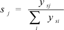
where out is the vector of the desired joint angles given to the PD to control the movement of the joints of the fingers (this vector has 300 elements, one for each step of the trial, with values in the range [0, 1]), OCPG-C, OCPG-M, and OCPG-S are the desired joint angles of the CPGs, ysj is the activation of the selector output unit j (to which a noise component was added as in Eq. (3)), and sj is the normalized activation of the selector output unit j. Examples of sequences of values of one element of the out vector (Equation 4) are provided in Table 5 (Appendix, Section 7.2). Vector out is then remapped onto the movement range of the controlled joints.
2.2.2 Critic: Functioning and learning
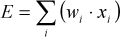
As for the experts and the selector, the critic also receives as input the object size and shape. The output of the critic is a linear unit providing the evaluation E of the currently perceived state based on the critic connections weights wi (Figure 1b). The evaluation E is expressed as:
The critic output is used to compute the TD-error [8] which determines whether things have gone better or worse than expected. Formally, TD is defined as TD=R-E, where R is the reward. The reward is proportional to the object rotation. The TD-error is used to update the critic connection weights wi as follows:

where ηE is the critic learning rate (see Table 2). The rationale of this learning rule is as follows. Through learning, the critic aims to progressively form an estimate E of the reward delivered by the current parameters of the CPGs. A TD>0 means that the estimation E, formulated in correspondence to the state xi, is lower than the reward R actually received. In this case, the learning rule increases the connection weights of the critic in order to increase E. Instead, a TD<0 means that the estimation E is higher than the reward R, so the connection weights of the critic are decreased in order to decrease E.
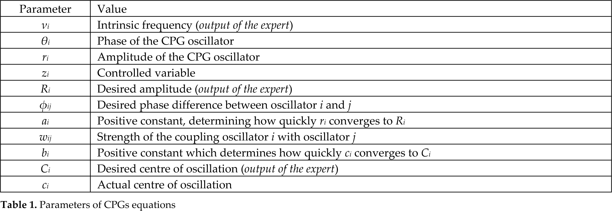
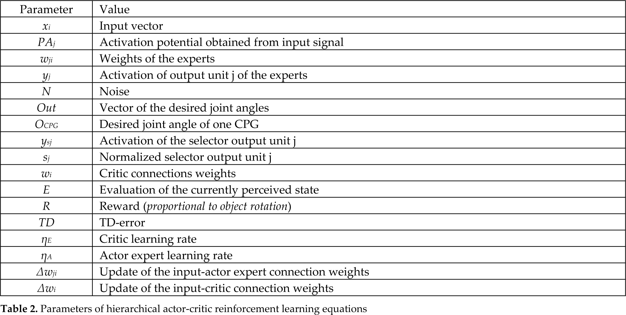
Table 1 and Table 2 explain the parameters and the values taken by constant parameters. The parameters Ri, vi,φij and Ci are outputs of the expert and their value is determined by learning during the training phase and is included in the interval indicated in Table 1.
Parameters of CPGs equations
Parameters of hierarchical actor-critic reinforcement learning equations
The values of the parameters of the hierarchical actor-critic reinforcement learning equations and of the CPGs equations are listed in the Appendix (Section 7.2).
2.2.3 Actor experts and selector: Learning
The TD-error is also used to update the input-actor expert connection weights wji, thus yielding

where ηA is the actor expert learning rate and (yj (1-yj)) is the derivative of the sigmoid function. The rationale of the learning rule is as follows. A TD> 0 means that the actor, thanks to yjN, reached a reward/state that is better than the one achieved on average based on yj. In this case, the learning rule updates the actor connection weights so that, in correspondence to xi, yj progressively approaches yjN. Instead, a TD<0 means that the actor (yjN) reached a reward/state that is worse than the one achieved on average based on yj. In this case the connection weights are updated so that yj moves away from yjN.
The selector connections weights are updated in the same way as those of the experts. Here, however, the effect of the application of the learning rule is that the selector will update its connection weights so as to increase the responsibility of those experts (CPGs) which contribute to a positive TD-error.
2.3 CPGs models
CPGs are used to produce cyclic trajectories and are modelled as coupled oscillators, each controlling a different thumb and index DOF. In this paper a modified version of the CPG proposed in [14] was used. Formally, as in [14], a single oscillator is expressed as follows:


where θi and ri are, respectively, phase and amplitude of the CPG oscillator i at each step, zi is the controlled variable (i.e. the joint angle), Ri is the desired amplitude, vi is the intrinsic frequency, ai is a positive constant determining how quickly ri converges to Ri, φij is the desired phase difference (coordination delay) between oscillator i and oscillator j of the CPG, wij establishes the strength of the coupling of oscillator i with oscillator j of the CPG (see Table 2). The evolution of the phase θi depends on the intrinsic frequency vi, on the coupling wij and on the phase lag φij of the coupled oscillators. According to Eq. (10), amplitude variable ri smoothly follows Ri with a damped second order differential law.
An additional relation is considered as having the possibility of regulating the centre of oscillation of each oscillator. It is expressed as:

where Ci is the desired centre of oscillation of the oscillator i, ci is the actual centre, and bi is a positive constant that determines how quickly ci converges to Ci. To control the centre of oscillation, the value of ci has to be substituted to 1 in Eq. (11) so the oscillation based on the cosine takes place around such a value. Our previous work [40] has shown that the addition of Eq. (12) allows the improvement of system performance in manipulation tasks.
Variable Ci enables oscillations around any position of the joint. As a result, each CPG is controlled by four parameters: Ri (desired amplitude); Ci (desired oscillation centre); vi (desired oscillation frequency), and one parameter for each coupling with the other oscillators (For simplicity, in the simulations φij and wij were set to 1).
The CPGs used in this work are shown in Figure 2. Figure 2.a shows in detail the complex CPG (GPG-C) which has four oscillators: N1 generates the desired angle of the flexion/extension of the index (FEI); N2 generates the desired angle of the adduction/abduction of the index (AAI); N3 generates the desired angle of the flexion/extension of the thumb (FET); and N4 generates the desired angle of the opposition of the thumb (OT). In this case the expert produces 12 CPG parameters: vCPG-C, R1CPG-C, R2CPG-C, R3CPG-C, R4CPG-C, C1CPG-C, C2CPG-C, C3CPG-C, C4CPG-C, φ12CPG-C, φ13CPG-C, φ34CPG-C. Figure 2.b shows the medium complexity CPG (GPG-M) which has two oscillators: N1 generates the desired angle for both FEI and FET; N2 generates the desired angle for both AAI and OT. The expert of this CPG produces six parameters: vCPG-M, R1CPG-M, R2CPG-M, C1CPG-M, C2CPG-M, φ12CPG-M. Figure 2.c shows the last simple CPG (CPG-S) which has only one oscillator, N1, that generates the desired angles for all DOFs. The expert of this CPG produces only three parameters: vCPG-S, R1CPG-S, C1CPG-S. In the case of the hierarchical system, one intrinsic frequency vCPG-H is used for all the oscillators.
The three CPGs used in the model, which have different levels of complexity. (a) CPG-C with four oscillators (N1, N2, N3, N4). (b) CPG-M with two oscillators (N1, N2). (c) CPG-S with one single oscillator (N1). AAT indicates adduction/abduction of the thumb, OT indicates opposition of the thumb, AAI indicates adduction/abduction of the index, FET indicates flexion/extension of the thumb and FEI flexion/extension of the index.
2.4 The Proportional Derivative (PD) controller
The CPG output (desired joint angles) is sent to a PD controller and undergoes gravity compensation in the joint space. This generates a torque as follows:
where T is the torque vector applied to the thumb and index joints, g(q) is the gravity compensation component, KP and KD are definite positive diagonal matrices, q˜ is the difference between the desired and the current joint angle vectors, q̇ is the angular velocity vector [41, 42, 43].
2.5 The manipulation task
The task requires that the robotic hand develop cyclic manipulation capabilities in order to rotate objects of different shapes and sizes (spheres, cylinders and cubes) around an axis. The rotational axis of objects is perpendicular to the hand palm and is anchored to the world, thus allowing the object to rotate whenever at least one finger touches it. This task is an abstraction of the real life tasks requiring the coordination of two fingers, as in the case of unscrewing bottle caps. Friction is set so that in some pilot experiments one finger was capable of rotating the objects. Figure 3 shows an example of a manipulation task involving the simulated hand and a cylinder.
The neural controller is tested on two simulated robotic hands with different thumb DOFs (the iCub hand and the DLR/HIT hand II, see Subsect 2.6 for more details), and controls the thumb and index joints of the hand.

(a) Snapshots of the manipulation task. The object in the figure is the sphere with a radius of 0.032 m. (b) The robotic setup used to test the neural controller. The rotating axis of the manipulated cylinder is drawn in black. (c) The initial position of the iCub hand with all the manipulated objects (d) The initial position of the DLR/HIT hand II with all the manipulated objects.
Figure 3 (a) shows the snapshots of the iCub hand during the manipulation of a sphere with a radius of 0.032 m. The first snapshot displays the starting position of the iCub hand with respect to the object. In this position the thumb is parallel to the other fingers with a null opposition angle. During the execution of the task the thumb can exploit the flexion/extension DOF of the MCP joint (coupled with the IP joint) and the opposition DOF. These degrees of freedom allow the hand to touch the object and enable it to rotate the object.
The model is trained for 5000 trials, each time with a different object. At the end of every trial, each of which lasts 300 cycles, the rotation angle of the object is normalized and used as reward signal for the hierarchical reinforcement learning neural controller (see Subsect. 2.3). Based on this reward, the neural controller learns to modify the initially random thumb and index fingers cyclic movements in order to acquire coordinated functional cyclic movements, useful for rotating the object as fast as possible.
The proposed manipulation task is quite challenging for several reasons. First, the neural controller has to learn on the basis of the rare feedback based on the scalar value of reinforcement given at the end of each trial. This generates difficulties due to time and space credit assignment problems well-known within the reinforcement learning literature [10] (this rare feedback mirrors the conditions in which organisms acquire behaviours by trial-and-error). Second, the same neural controller is required to learn to control different robotic hands with different thumb features: no adjustment is made to adapt the controller architecture to the different kinematic features of the two hands (asides from the number of outputs channels used) as the model is asked to adapt to the different hardware features based on its adaptive capabilities. Third, the model is asked to search for solutions to the rotation task for objects of different shapes and sizes requiring different manipulation movements. Lastly, the rotation of the objects requires difficult dynamical movements, potentially benefiting from a sophisticated coordination between the controlled finger joints.
2.6 The robotic hands
The same neural controller (Figure 1 b) is used to drive the manipulation behaviour of two different simulated anthropomorphic robotic hands: the iCub hand (Figure 4 a, b) and the DLR/HIT hand II (Figure 4 c, d). A comparative analysis has been carried out during the manipulation tasks involving the two hands and all the objects (see Sec. Results). The hands and the environment are simulated using the NEWTON physical engine library with an integration step set to 0.01s. Both simulated hands are anthropomorphic meaning that they try to approximate the kinematic and dynamic models of real human hands. This has been guaranteed by an accurate study of dynamic and kinematic features of the real robotic hands and the implementation of these features in the simulated hands. For instance, the dynamic features of the DLR/HIT hand II were calculated based on the finger and motor parameters reported in [29]. The dynamic parameters of the hands considered in the simulation are given in the Appendix (Section 7.1). A systematic analysis of the correspondence between the torque command of the real robotic hands and the torque command provided to the simulated hands was carried out.

The two robotic hands used in the manipulation task. (a) The iCub hand; (b) The kinematic structure of thumb, index and middle fingers of iCub hand used to simulate the manipulation task. (c) The DLR/HIT h and II; (d) The kinematic structure of thumb, index and middle fingers of the DLR/HIT hand II used to simulate the manipulation task.
The iCub robotic hand (Figure 4 a), which has the same size of a 2-year old child hand, has five fingers with 20 joints and 9 actuated degrees of freedom in total (DOFs) [28]. In particular, the thumb has four joints: two uncoupled joints (opposition and abduction/adduction) and two coupled joints (PIP proximal interphalangeal joint and DIP distal interphalangeal joint flexion/extension). The index and middle fingers have one uncoupled joint (the MCP metacarpophalangeal flexion/extension) and two coupled joints (PIP and DIP flexion/extension); the abduction/adduction joint of the index, ring and little finger is actuated by a single motor. The joints of the other fingers (ring and little) are coupled by a single motor (MCP, PIP and DIP flexion/extension). The fingers are 0.068m of length and have a diameter of 0.012m. The 20 joints are actuated using nine DC brushed motors (two in the hand and seven in the forearm).
The DLR/HIT hand II (in Figure 4 c), which is slightly bigger than an adult human hand (finger length: 169 mm; diameter: 20 mm), is composed of five identical fingers with 20 DOFs in total and 15 motors. Each finger (including the thumb) has four joints with three actuated DOFs: adduction/abduction, MCP flexion/extension and PIP flexion/extension. The PIP and DIP joints are mechanically coupled with a 1:1 ratio [28]. The thumb is constrained to have a fixed opposition of 35° in the xy-plane and an inclination, with respect to z-axis, of 44° (Figure 4 c). The DOFs are actuated by flat brushless DC motors embedded in the fingers and the palm.
The two hands have two important differences: the size (as explained above) and the degree of freedom of the thumbs. In particular, in the iCub hand the thumb opposition is an active DOF [0°, 120°] actuated by a single motor; on the other side, in the DLR/HIT hand II the thumb has a fixed opposition. It should be noted that, despite the fact that the two hands are rather different, the proposed hierarchical reinforcement learning neural architecture is able to autonomously develop successful motor skills to solve the manipulation task with both.
In the simulation trials only four DOFs were controlled: two DOFs of the index finger and two DOFs of the thumb; all other DOFs were kept to fixed values. This choice is the result of a careful preliminary analysis of the DOF more involved in the addressed task.
The four DOFs controlled on the iCub hand were:
Index finger: PIP flexion/extension (F/E) joint with a range of motion (ROM) of [0°, 90°] (PIP and DIP are mechanically coupled) and MCP adduction/abduction (A/A) with a ROM of [−15°, 15°] (MCP and PIP are mechanically coupled).
Thumb finger: MCP flexion/extension joint with ROM of [0°, 90°] (MCP and IP are mechanically coupled) and opposition (O) of the thumb [0°, 130°].
The four DOFs controlled on the DLR/HIT hand II were:
Index finger: PIP flexion/extension (F/E) joint with ROM of [0°, 90°] (PIP and DIP are mechanically coupled 1:1) and MCP adduction/abduction (AA) with ROM of [−15°, 15°].
Thumb finger: PIP flexion/extension (F/E) joint with range of motion of [0°, 90°] and MCP adduction/abduction (A/A) with ROM [−15°, 15°]. In this phase of preliminary explorations the coupling between the PIP and DIP joints of the DLR thumb was not considered. This issue will be investigated in the future to understand if and how this coupling constrains the learning of fine manipulation tasks.
3. Validation Tests and Results
3.1 Validation Setup
The hierarchical bio-inspired architecture in Figure 1 was trained and tested on the two simulated robotic hands (i.e. the iCub hand and the DLR/HIT hand II) interacting with nine different objects: “small sphere”, “medium sphere”, and “large sphere” with a radius of 0.028 m, 0.032 m, and 0.036 m, respectively; “small cylinder”, “medium cylinder”, and “large cylinder” with a radius of 0.028 m, 0.032 m, and 0.036 m, respectively; “small cube”, “medium cube”, and “large cube” with an edge size of 0.028 m, 0.032 m, and 0.036 m, respectively.
The object position was fixed in front of the index finger, in a central location between thumb and index, in order to facilitate contact with the object by both fingers (Figure 3). As a consequence, the starting position was different for the two hands, depending on the hand dimensions. Each hand was tested with each object and their learning capability was studied by observing the total object rotation angle caused by the hand in each trial.
Values of diagonal Kp and Kd matrices for the control of the index and thumb fingers of the iCub hand were fixed to:
Index: Kp=[500, 500, 500]; Kd=[10, 10, 10];
Thumb: Kp=[300, 300, 300]; Kd=[10, 10, 10];
Values of diagonal Kp and Kd matrices for the control of the index and thumb fingers of the DLR/HIT hand II were fixed to:
Index: Kp=[450, 300, 300]; Kd=[27, 20, 20];
Thumb: Kp=[600, 300, 150]; Kd=[27, 20, 20];
The values of the Kp and Kd matrices were empirically chosen. For both hands, the Kp and Kd matrices were set in order to minimize the difference between the actual and desired joint trajectories (i.e. joint position error) and to optimize motion tracking.
The different CPG models (i.e. CPG-C, CPG-M, CPG-S and CPG-H described in Sect. 2) have been tested with each of the nine objects separately. At the beginning of each trial the hand assumed the starting position, whereby all the fingers are in a straight configuration.
In the following section, results for each hand are reported separately in order to show the performance of each hand engaged in manipulating the nine objects with each of the four CPG models; finally, a comparative analysis of the two hands is presented.
3.2 Results for the iCub hand
In Figure 5, the reward course during learning is shown for each object and for the four CPG models. Furthermore, Table 3 reports the reward values achieved at the end of each training using objects of different shapes and sizes. It can be observed that, for small and medium objects, the best performance is typically achieved by the hierarchical model (CPG-H); for the large objects, the CPG-C model outperforms the hierarchical one. Moreover, the systems' performance is notably affected by variability in object shape and dimension. In particular, the reward values decrease with the increase of the object dimension because, for smaller objects, the fingers have to cover a smaller distance to achieve a certain rotation of the objects. This result is also explained by the small dimension of the hand (replicating the dimensions of a 2-year-old child's hand), which facilitates the manipulation of small objects.

Reward obtained of the iCub hand engaged in learning to rotate each of the nine different objects during 5000 learning trials. The curves of each graph represent the rewards obtained during learning with CPG-S, GPG-M, CPG-C, and CPG-H.

Contact of index and thumb fingers of the simulated iCub hand during the cyclic manipulation of a large sphere with the four different CPGs. The graphs show four different states: no touch, touch with only index, touch with only thumb, touch with both fingers.

Contact of index and thumb fingers of the simulated iCub hand during the cyclic manipulation of a small sphere with the four different CPGs. The graphs show four different states: no touch, touch with only index, touch with only thumb, touch with both fingers.
Comparison of the rewards obtained with iCub hand for different CPG models and different objects. Each cell indicates the mean value of the reward at the end of the learning.

The best reward values for every object are indicated in bold. The hand achieves the best performance with the spheres and the worst performance with the cubes. This is caused by the presence of edges on the cubes that make the fingers get stuck on them, thus reducing the effectiveness of low-range movements.
A further important issue to analyse in the comparative study of the different CPG models is the involvement of the thumb and the index finger in the manipulation task. Indeed, it was expected that the different performance of the four CPG models was directly related to the level of cooperation between the two fingers involved in the task. Take for example the case of the large sphere. In this case, the highest reward value is achieved by the CPG-C model (Table 3). The performance of the CPG-H and CPG-M is close to the CPG-C reward, while the use of the simple CPG model (CPG-S) provides a reward value that is substantially smaller. It is noteworthy that CPG-S is characterized by the absence of contact between the thumb and the object, thus showing the importance of the action of the thumb in successfully handling the object (Figure 6). This is also confirmed in the case of the small sphere (Figure 7), where the contact by the thumb is decisive in reaching the highest reward values of CPG-H: the use of the thumb leads to a high performance whereas the other models fail to achieve it.
In Figure 8 the trajectories in the 3D space of the thumb and index tips show how the hierarchical CPG model is able to alternate between both fingers during contact with the object. The CPG-C, instead, fails to learn to use the thumb, which oscillates far away from the object.
Trajectories followed by the fingertips of the iCub hand during the manipulation of a small sphere (the gray circle marks its position). (a) Trajectories generated by the CPG-C model. (b) Trajectories generated by the CPG-H model. Notice how only the CPG-H is capable of contacting the object with both the index and the thumb.

Examples of the trajectories of the iCub hand controlled joints at the end of the training with the small sphere. For each couple of graphs (e.g., the two graphs of “Index Flexion-Extension”), the upper graph shows the real trajectory of a joint generated by the three single-CPG models (CPG-C, CPG-M, CPG-S), whereas the lower graph shows the desired and real trajectories generated by the CPG-H model. The four couples of graphs refer to the four iCub controlled joints DOFs: FEI, AAI, FET, and OT.
Figure 9 shows an example of the trajectories followed by the joints when controlled with the different CPG models (CPG-C, CPG-M, CPG-S, CPG-H) during a manipulation of a small sphere. In the case of the CPG-H, the figure also reports the desired joint trajectory calculated with the CPG equations.
Passing now to the analysis of the joint trajectories (Figure 9), the first interesting consideration concerns the similar oscillation frequency shown by the different CPG models. This suggests that the system found the same reliable frequency under different conditions. Moreover, it is evident from the figures that the model exploits the possibility of regulating the oscillation centres so that they have good contact with the objects. For example, the displacement of the centre of the oscillation of the thumb flexion extension joint caused by CPG-H near the object allows the thumb to have contact with the object and so to increase the reward value (see Figure 5). In this respect, notice how the desired centres of the oscillation of FET of the single-CPG models are below 0.5, whereas that of the CPG-H is above 0.5. The same considerations are also valid for the thumb opposition trajectories. This confirms the higher flexibility of the CPG-H that allows the iCub hand to discover differently from the other models the advantage of using both fingers.
3.3 Results for the DLR/HIT hand II
Figure 10 shows the compared analysis of the four different CPG models in terms of rewards obtained by the DLR/HIT hand II in the learning phase during the interaction with the nine different objects. Moreover, the mean values of the reward achieved by the DLR/HIT hand II at the end of the 5000 learning trials during interaction with the nine different objects are listed in Table 4.
Table 4 and Figure 10 demonstrate that the complex CPG model (CPG-C) outperforms all the others in the manipulation of spherical and cylindrical objects; on the other hand, the hierarchical CPG model (CPG-H) achieves the best reward values with the cubes.
As for the iCub hand, it was expected that the different performance of the four CPG models was directly related to the level of cooperation between the two fingers involved in the task (i.e. the thumb and the index finger). To this purpose, the index and thumb's contact with the manipulated objects was monitored for each object. Figure 11 shows a representative case of the contact of the index and the thumb in the manipulation of a large sphere with the four different CPG models.
It is interesting to observe a correspondence between the number of contacts that the thumb has and the quality of the final achieved performance: the reward is higher when the number of contacts is higher and the thumb is perfectly alternated with the index. For instance, the CPG-S does not exploit the thumb contact to rotate the object and has the lowest final reward value with respect to the other CPG models. It is apparent from the figures that when the system learns to use two fingers to handle the object, it also learns to alternate and coordinate them to increase the rotation applied to the objects. Indeed the CPG-C, which enables the highest number of thumb contacts alternated with the index finger (also with respect to the CPG-H), achieves the best reward (Table 4).
Comparison of the rewards obtained with DLR/HIT hand II for different CPG models and different objects. Each cell indicates the mean value of the rewards at the end of the learning. The best reward values for every object are indicated in bold.


Reward obtained of the DLR/HIT hand II engaged in learning to rotate each of the nine different objects during 5000 learning trials. The curves of each graph represent the rewards obtained during learning with CPG-S, GPG-M, CPG-C, and CPG-H
Contact of index and thumb fingers of the simulated DLR/HIT hand II during the cyclic manipulation of a large sphere with the four different CPGs. The graphs show four different states: no touch, touch with only index, touch with only thumb, touch with both fingers.

Trajectories followed by the fingertips of the DLR/HIT hand II while manipulating a large sphere (the gray circle marks object position). (a) Trajectories generated by the CPG-S model. (b) Trajectories generated by the CPG-C model.

Examples of trajectories of the DLR/HIT hand II controlled joints at the end of training with the large sphere. For each couple of graphs from the top (e.g., the two graphs of “Index Flexion-Extension”), the upper graph shows the real trajectory of a joint generated by the three single-CPG models (CPG-C, CPG-M, CPG-S), whereas the lower graph shows the desired and real trajectories generated by the CPG-H model. The four couples of graphs refer to the four DLR/HIT hand II controlled joint DOFs: FEI, AAI, FET, and AAT.
Contact of index and thumb fingers of the simulated DLR/HIT hand II during the cyclic manipulation of a small cube with the four different CPGs. The graphs show four different states: no touch, touch with only index, touch with only thumb, touch with both fingers.
Figure 12 shows the trajectories in the 3D space of the thumb and index tips during the manipulation of a large sphere for the worst case (i.e. CPG-S) and the best case (i.e. CPG-C). The figure confirms that the complex CPG model (CPG-C) is able to use both fingers during the task, touching the object in an alternate fashion. The CPG-S, instead, fails to learn how to advantageously use the thumb, thus moving it away from the object in order to avoid negatively interfering with its rotation.
Figure 13 shows the real trajectories of the DLR/HIT hand II followed by the joints when controlled by the four CPG models during a manipulation of a large sphere. Observe that the trajectories generated for the index joints have a similar amplitude and centre of oscillation for all the CPG models; the main difference is obtained for the thumb adduction abduction joint: only the CPG-C causes the oscillation of the joint around a centre that is located in the upper part of the range of motion, thus resulting in the contact between the thumb and the object.
The positive effect of the thumb contact on the object rotation is observed during the manipulation of spherical and cylindrical objects. On the other hand, it is not confirmed in the case of cubic objects. First of all, for cubic objects the best performance is achieved by CPG-H, characterized by the absence of thumb contacts (Figure 14). This is probably due to the geometrical features of the cube, characterized by the presence of the edges. Unlike the case of objects with smoother surfaces, such as spheres and cylinders, for the cubes the action of the thumb seems to hamper object rotation more than facilitate it. As a confirmation it is worth noticing that the worst values of rotation are obtained in the case of CPG-C (Table 4) that enables a higher number of contacts by the thumb with the object (Figure 14).
3.4 Comparative analysis of the two hands
A comparative performance analysis of the two anthropomorphic robotic hands (DLR/HIT hand II and iCub hand) has been carried out during manipulation tasks involving all the nine objects. Observing the reward values in Tables 1 and 2, it is evident that both robotic hands learn to manipulate all the objects, although the reward obtained by the simulated iCub hand is always higher than the reward achieved by the simulated DLR/HIT hand II. The main reason is that the iCub hand can gain an advantage from the exploitation of the thumb opposition (lacking in the DLR/HIT hand II) to increase the rotation of the manipulated object. In addition, the more positive results achieved by the iCub hand can be related to the size of the hand, the slim fingers of which can touch the objects more easily and comfortably compared to the DLR/HIT hand II fingers. This is also demonstrated by the significant decrease of reward values in the iCub hand with the increase of the object size (Figure 5, Table 3), while the performance of the DLR/HIT hand II is quite invariant with respect to the object size (Figure 10, Table 4). Therefore, although the iCub hand always achieves better results, the DLR/HIT hand II has more relevant generalization capabilities for different objects; for DLR/HIT hand II the reward values for various objects differ by fractions of a unit, while for the iCub hand they differ by whole units (Tables 3, 4). The performance variability of the system with respect to the different CPG models (Figure 5, 10) is higher with the iCub hand with respect to the DLR/HIT hand II.
The positive effect of the coordinated action of the two fingers in the manipulation task is verified for both robotic hands. The best performance is achieved when the thumb touches the object alternatively with the index, thus causing higher object rotations. Indeed, the CPG models that maximize system performance are in most cases the CPGs enabling a coordinate thumb-index finger action. The sole exception to this is the case of the DLR/HIT hand II handling the cube (Figure 14). The reason for this exception is twofold. On one hand, the cube has edges that make the fingers get stuck; on the other hand, the DLR/HIT hand II lacks the thumb opposition, thus limiting the hand's manipulation capabilities. For the cube, the action of the thumb (due to AA and FE joints) seems to be disadvantageous when it touches the object (Figure 14).
Finally, Figures 15 - 18 show an important peculiarity of the proposed hierarchical architecture: the CPG-H is capable of using many CPGs by suitably mixing them. In particular, Figures 15 and 17 show the capabilities of CPG-H in solving the same task and achieving comparable results with different combinations of the single CPG models. Figure 16 shows that, for two different learning runs for the iCub hand with the same final reward value, the same task can be solved by a system with different mixed combinations of the CPGs. This is similar to the DLR/HIT hand II in Figure 18. A possible explanation of this is that while some combinations of CPGs clearly lead to a bad performance, and so are discarded by the system, the tasks solved here can have multiple solutions, all allowing the system to achieve a high level of performance, so the system selects any one of them due to noise factors. The CPG-H model is not able to account for the direct contribution of each CPG to the manipulation task and maximize the contribution of the best one in the weighted combination, but it can always approach the task with different mixed combinations of the CPGs able to achieve the maximum rotation.

Activations of the selector output units (gates) that the CPG-H develops in two training sessions using the small sphere with the iCub hand.
Reward obtained by the iCub hand engaged in learning to rotate the small sphere during two different training session of 5000 learning trials with the CPG-H model.

Activations of the selector output units (gates) that the CPG-H develops in two different training sessions while handling the small sphere with the DLR/HIT hand II.

Reward obtained by the DLR/HIT hand II engaged in learning to rotate the small sphere during two different training session of 5000 learning trials with the CPG-H model.
4. Conclusions
This paper has proposed a bio-inspired hierarchical neural architecture based on a reinforcement learning model that autonomously develops manipulation skills using two robotic hands with different kinematic features. The model was grounded on the following key bio-inspired computational principles: (a) central pattern generators (CPGs) support the cyclic movements of upper-limbs; (b) trial-and-error processes play a key role in learning and setting the parameters of these CPGs; (c) and a mixture of different CPGs, controlled in a hierarchical fashion, are used in the solution of different manipulation tasks.
Although these assumptions need further empirical support, the model shows interesting computational features that make it a useful tool to study dexterous movements in robots and also to study the development of cyclic manipulation skills in infants, in particular to investigate the processes involved in the transition from unstructured cyclic manipulation movements to functional ones. In this respect, the results show that the model is able to discover suitable combinations of CPGs to be used and to suitably set their parameters, depending on the physical features of the objects to be manipulated. Moreover, the model is able to learn quite fast when it can use ensembles of CPGs (by finding suitable mixtures of CPGs with different complexities) versus a single CPG (even complex), though this involves searching for a higher number of parameters. These results are useful for the robotic control of tasks that involve cyclic actions.
The comparative analysis of the effects of different kinematic structures on dexterous movements, based on the iCub robot hand and the DLR/HIT hand II, shows how the reduced size and the opposition of the thumb of the iCub hand advantageously influence manipulation capability in the performed manipulation tasks. In particular, the presence of thumb opposition in the iCub hand allows the object to be touched several times by both the thumb and the index thus maximizing the rotation. On the other hand, the DLR/HIT hand II exhibits a lower performance variability with respect to object shape and size due to the simpler manipulation strategies developed that involve little/no use of the thumb.
Future work should investigate the specific role played by different CPGs in the hierarchical architecture, for example by studying the functioning of couples of CPGs of different sophistication. This investigation should in particular aim to understand why and how the system uses the particular mixtures of CPGs found in the experiments. Moreover, future work should test of the learning capabilities of the model in an experimental scenario involving the real version of the robotic hands. Further, it should find stronger empirical support for the core biological assumptions of the model so that the results obtained with the model can be used as empirical predictions to be tested in future experiments. Even before these future developments, however, the model presented here has been shown to be a promising tool to investigate the autonomous acquisition of cyclic manipulation skills in robots and also, due to its bio-inspired architecture and the behaviour that has been demonstrated, is a tool for studying the emergence of such skills in primates.
7. Appendix
7.1 Hand dynamic parameters
The dynamic parameters of the DLR/HIT hand II considered in the simulation are the following:
Total mass of the finger:0.220 kg
Mass of the proximal link: 0.0694 kg
Mass of the medial link: 0.0274 kg
Mass of the distal link: 0.0253 kg
Inertial matrix of the proximal link:

Inertial matrix of the medial link:

Inertial matrix of the distal link:
The model of the iCub hand relies on the kinematic and dynamic parameters available at http://www.robotcub.org. The hand is 50 mm long and 34 mm wide at the wrist, 60 mm wide at the fingers and 25 mm thick. Dynamic properties of the iCub hand considered in the simulation are listed below:
Mass of the proximal link: 0.012 kg
Mass of the medial link: 0.011 kg
Mass of the distal link: 0.011 kg
Inertial matrix of the proximal link:
Inertial matrix of the medial link:
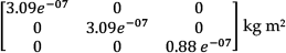
Inertial matrix of the distal link:

7.2 CPG parameters and outputs
The parameters of the hierarchical actor-critic reinforcement learning equations and of the CPGs equations had values in the following ranges:
vi [0, 6]
Ri [0, 1]
φij [−3, 3]
ai set to 20
wij set to 1
bi set to 20
Ci [0, 2]
N gradually moving from [−0.5, 0.5] to [−0.05, 0.05])
ηE set to 0.1
ηA set to 0.1
Examples of output values produced by a CPG (see Equation 4) are shown in Table 5. They are the values obtained for generating the flexion/extension trajectories of the PIP index joint of the DLR/HIT hand II for different sizes of the sphere.
Examples of the Out vectors (Equation 4) generating the flexion/extension trajectories of the PIP index of the DLR/HIT hand II during the manipulation of spheres of different sizes. They are related to two different motion phases: approaching the object and moving away from the object. The listed values are normalized in a range between [0,1].

Footnotes
18. Acknowledgments
This work was supported by the national project PRIN 2010 “HANDBOT - biomechatronic hand prostheses endowed with bio-inspired tactile perception, bidirectional neural interfaces and distributed sensorimotor control”, and “ITINERIS 2” on the technological transfer, CUP: F87G10000130009. It was also supported by the EU funded project “IM-CLeVeR - Intrinsically Motivated Cumulative Learning Versatile Robots”, grant agreement ICT-IP-231722, FP7/2007-2013 “Challenge 2 - Cognitive Systems, Interaction, Robotics”.