
Abstract
As formal verification tools gain popularity, the problem arises of making them more accessible to engineers. A correct understanding of the logics used to express the properties of a system's behaviour is needed in order to guarantee that properties correctly encode the intent of the verification process. Writing appropriate properties, in a logic suitable for verification, is a skilful process. Errors in this step of the process can create serious problems since a false sense of safety is gained from the analysis. However, when compared to the effort put into developing and applying modelling languages, little attention has been devoted to the process of writing properties that accurately capture verification requirements. In this paper we illustrate how a collection of property patterns can help in simplifying the process of generating logical formulae from informally expressed requirements.
1. Introduction
The dependability of an automated system (e.g., its reliability, availability, maintainability) has a direct impact on people and goods safety. Guaranteeing the safe operation of a system requires a holistic approach to design that takes safety considerations into account from the early design stages through to operational exploitation.
Formal verification of software is becoming established as a useful and powerful technique for guaranteeing the correctness of software artefacts in general. This is also the case for industrial controller analysis [1]. Formal verification's main advantage is that it enables analysis of all possible system behaviour. Typical mentioned disadvantages relate to the time and computational resources needed for the attainment of formal verification results and to the level of expertise needed to apply the verification techniques. In this paper we address the latter issue.
In recent years, several approaches to applying formal verification techniques to automation system dependability have been proposed. These range from formal verification by theorem proving [2] to formal verification by model checking [3–6]. Model-checking [7], in particular, is becoming an established technique for the formal verification of Discrete Event Systems (DES) automation. A finite state system can be represented by a labelled state transition graph, where labels of a state are the values of the atomic propositions in that state (for example the values of the latches). The properties of the system are expressed as formulae in temporal logic. Model-checking (see Figure 1) consists of traversing the graph of the transition system and verifying that it satisfies the formula representing the property, i.e., that the system is a “model” of the property.

Model checking
Temporal logic formulae enable the expression of properties of the behaviour of the system, for example, properties of the internal states of the controller (e.g., safety and liveness properties of the controller model) [8], but also properties related to the plant model, such as the safety or liveness of its behaviour.
As verification tools gain popularity, the problem arises of making their use scale to more realistic settings. The applicability of such tools is affected by a number of factors, from the scalability of the algorithms being used as the size and complexity of the problems being faced increases, to their proneness to human error during the modelling and interpretation of results phases as potential users become less proficient in the verification techniques being applied. We refer to this latter aspect as the accessibility of the verification tools.
We have been working on the issue of making verification more accessible. In order to help the analysis of PLC (Programmable Logic Controller) programs, it is important to facilitate the use of automated reasoning tools. This can be done at several levels:
help in deducing the controller and plant models help in writing properties for analysis help in analysing the results.
Thus, support for formal verification ranges from helping the editing of models and properties, to helping the interpretation of verification results. One specific aspect that deserves attention is the writing of properties to be verified. Meaningful properties can be hard to write. This is even more evident when we consider the behaviour of complex automated systems, whose requirements are difficult to describe.
Writing a property for verification is a two-step process:
we must first identify what the relevant properties of a given system are then we must decide how to correctly express them in the logic of the verification tool.
Step 1 is domain dependent and largely relies on knowledge about the specific system being designed/verified and what its properties should be. Step 2 is a technical step. A correct understanding of the model, the requirement and the logic in which properties are expressed is needed in order to guarantee that the property being verified correctly encodes the intent of the verification process. This is a non-trivial step. As illustrated by [9] and [10], instances can be found in the literature where the logical formula used for verification does not correspond to what was intended. This is a serious problem since a false sense of safety is gained with the analysis.
The process is made more complex when the models are developed in such a way that verification must only be performed at certain specific points in the evolution of the system (for example, because not all states in the model represent actual system states).
In this paper we look at how the process of expressing properties can be supported. In order to ease the process, strategies can be applied, such as breaking down a property in smaller parts, or using observer automata to express the behaviour we want to verify. The former case begs the question of how to compose the results of the smaller verification steps [11]. In the latter case, we are increasing the complexity of the model. Our approach is to provide designers with patterns that can be instantiated to produce properties of interest. By studying and identifying the properties used for the verification of DES automation, it becomes possible to systematize the writing of such properties in an automatic way. A tool was been developed to support this approach.
In [10] we presented a study about the type of properties that are typically verified in industrial controllers using formal analysis techniques. The results of that study were systematized in a collection of patterns to help analysis. A tool was developed to support the approach. In this paper we develop the pattern collection further and illustrate how it can be used in a concrete example. Additionally, we describe the tool that has been developed to support the process and discuss how it can assist the process of defining relevant properties for verification.
The paper is structured as follows: Section 2 describes our approach to modelling and the impact it has on how properties must be expressed. Section 3 discusses property patterns and in particular those proposed by Dwyer et al. [9]. Section 4 presents a study of automation related properties and Section 5 introduces a new pattern collection for the automated production systems verification that resulted from the study. Section 6 presents the tool that was developed to support the use of patterns, Section 7 presents a case study and finally, in Section 8 we discuss the results that have been achieved.
2. Formal Verification
Formal verification techniques, model checking in particular, are exhaustive techniques. However, they are also time-consuming techniques when compared, for instance, to simulation and especially when a real case is being analysed. This is due to the complexity of the calculations performed. Indeed, obtaining a solution might not always be feasible. This is typically solved using abstraction to reduce the size of the models by removing unnecessary detail.
An automation system is always composed by a controller coupled with a plant (see Figure 2). The controller outputs are the plant inputs and the plant outputs are controller inputs. As part of a dependable controller design approach, the target verification system model may comprise [12] either the controller on its own, assumed to be in an open-loop on the plant (non model-based verification) or the controller + plant set interacting within a closed-loop (model-based verification).
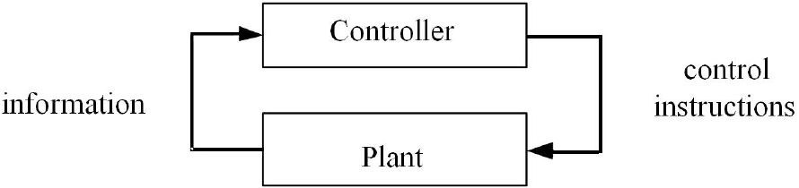
An automation system composed by a controller and a plant
The use of formal methods on industrial automation systems controller verification may be classified on three levels, taking into account three different criteria [12]:
The used method: Model-checking [13], Theorem-proving [2], Reachability analysis [14]. The adopted formalism: Petri Nets [15], Net Condition/Event Systems [16], Finite state machines [17]. The use (or not) of a plant model: (a) Non model-based, without considering a plant model, (b) Constrained-based, considering only some behaviour constraints (rudimentary model) and (c) Model-based, considering a real plant model, elaborated using a well-defined formalism. This model can be more or less refined depending on the behaviour properties that one intends to prove.
Many pieces of work are focused on the formal verification of industrial controllers without considering the plant modelling. Among them, the most significant are [8, 13, 18, 19].
There are other works that, although not considering an explicit plant model, consider the introduction of some system behaviour constraints and have thus improved the obtained results considerably [20].
In other work, the plant model was considered in an explicit way. Among them, the most significant are [15–17, 21] where the plant is modelled with the utilization of the following formalisms: Petri Nets, Finite state machines and Net condition/event systems.
In general, plant modelling is done using a monolithic approach and the plants that are modelled are small, when compared to the complexity of a standard industrial system. Such systems tend to be too complex to be modelled this way. When the plant is modelled using a modular approach [22], the global model of the plant is typically obtained from the Cartesian product of the modules that compose it. This allows the modelling of more complex systems. However, the global model becomes complex and has a higher dimension (number of states and transitions). To control this, abstraction must be used. At the same time that unnecessary detail (for the verification task) is removed from the model, the model becomes more detached from the physical system. Hence, situations and states appear that do not have a physical signification. For example, due to abstraction the model might need to perform internal calculations that do not directly correspond to any physical state. States in the model that do have a physical signification are called stable states (see, for example, [6]).
In the works studied, when a plant model is used, a reduction of the reachable states of the controller model is performed. With the restriction imposed by the plant model, some states of the obtained global model are not reached because the plant behaviour model imposes restrictions on the controller model, making the model more realistic. In this case, there are behaviour properties that can only be proved when the plant model is taken into account, especially liveness properties.
Another important aspect that must be taken into account is the detail of the plant model considered. In fact, this factor directly affects the global model obtained for the automation system (a higher number of states has a direct influence on the global computation time). The kind of properties that become possible to prove is directly related to the plant model's level of detail.
3. Property specification patterns
A number of classifications for property specifications in the context of model checking approaches have been proposed. Manna and Pnueli [23] used a syntactic approach, proposing a taxonomy of LTL (Linear Time Logic) formulae. The taxonomy is based on the operators used in each formula, therefore it covers all possible specifications that can be expressed in the logic. The categories they define, however, tend to be rather broad and came from a theoretical perspective. While they can be useful in classifying existing specifications, they provide little support for the process of generating new ones.
In [24] the same authors proposed a more pragmatic approach. A proof system that handles three basic types of property:
invariance — expressing that something holds in all states of the system (for example, the liquid in a tank will always remain below a predefined maximum value) response — expressing cause-effect relations (for example, if the tank becomes full the output valve will be open) precedence — expressing something must happen before something else (for example, before the valve is closed, the tank must be empty).
The term “design pattern” was first introduced by Gamma et al. [25] as a means of capturing and transmitting experts' knowledge in the field of object-oriented design. A pattern is not simply a mechanism to classify some artefact (be it an object-oriented design, or a property specification) into a category. A pattern's goal is to capture proven solutions to known problems and demonstrate how they can be used in practice to solve the same or similar problems in new situations.
With the above in mind, Dwyer et al. [9] proposed a system of property specification patterns. They carried out an extensive review of published property specifications and identified recurring patterns, which they organized into a hierarchy.
For each pattern a description that includes the pattern's intent, examples and known uses, relationships to other patterns and mappings to different logics (in particular, LTL and CTL – Computational Tree Logic [26]) are provided. Additionally, the patterns can be tailored with scopes: they can be applied to the whole of the model's behaviour, or be restricted to work between specified conditions.
A full account of all the patterns is out of the scope of this paper. Briefly, three classes of patterns are identified: occurrence (dealing with whether specific conditions are verified in the behaviour of the system), order (dealing with the order in which events/conditions occur) and compound (dealing with chains of events/conditions). Some of the most relevant patterns are:
absence – a given state/event (P) does not occur (in CTL this is expressed as “AG(¬P)”) universality – a given state/event (P) occurs always (in CTL this is expressed as “AG(P)”) response – a given state/event (P) must always be followed by a state/event (Q) (in CTL this is expressed as “AG(P →AF(Q))”) precedence – a given state/event (P) always precedes some state/event (Q) (in CTL this is expressed as “A[¬Q W P]”)
4. A study of automation related properties
Patterns do not provide concrete solutions. Instead, they provide templates that must be tailored for specific purposes. Hence, when attempting to apply the patterns to a specific area two issues arise:
The patterns should capture the relevant knowledge for the specific area being considered. Is all the relevant knowledge (or, at least, enough of the relevant knowledge) captured by the current set of patterns being used? The manner in which the properties are formulated should be adequate to the logics and modelling approaches used in the area of interest. Are the languages and encoding strategies used in the patterns adequate?
In order to answer these two questions we carried out a study of property specifications in the area of automation control of discrete systems (our area of interest in the current context).
The objective of the study was similar to that in [9]: to collect properties used in the literature and look for possible patterns. The justification for performing a new study of this type was twofold. On one hand, the original study was already a number of years old, begging the question of whether new patterns had arisen. On the other hand, we were interested in a particular application domain of the verification technology (discrete systems controllers) and in determining whether domain specific patterns were being used in that context.
A number of papers and theses were analysed. Relevant examples are [4, 8, 18, 27, 28] (see also the pattern descriptions in Section 5). In many cases the papers concentrated mainly in the modelling approaches, with little being said about the verification itself. Consequently, in those cases little information was provided about which properties were verified and how they came about. This reinforced our perception that work is needed in this area.
A total of six main case studies were analysed, resulting in over 70 property specifications. These properties were then aggregated into classes according to their syntactical structure and the type of application. These classes originated patterns for which LTL and CTL formulae were defined. The seven identified classes are the following (we provide typical formulations for illustrative purposes only, for a complete account of the patterns visit the patterns' web site
1
):
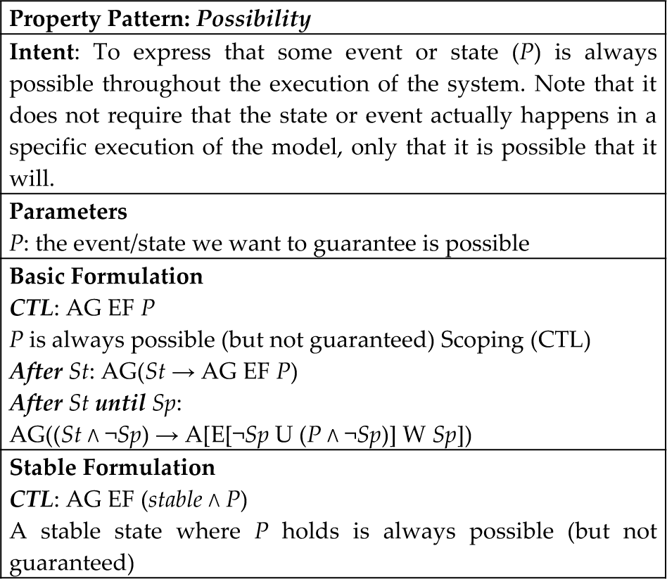
Possibility
“AG EF P”, meaning P is always possible
Fairness
“G F P”, meaning P occurs infinitely often
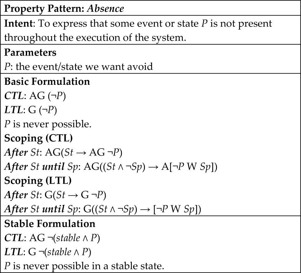
Absence
“G (stable→ ¬P)”, meaning P does not occur (in stable states)
Universality
“G P”, meaning P occurs in every state
Response
Eventual Response
“G (P → F Q)”, meaning after P, Q will happen
Immediate Response
“AG (P → AX(Q))”, meaning after P, Q will happen immediately next
Precedence
“A[¬Q W P]”, meaning P always precedes Q
Liveness
“AG(¬P → EF Q)”, meaning Q can occur after P.
Comparing these classes with the patterns defined by [9] we find that four of the classes corresponded to patterns in the patterns systems (3 to 6), while three of them do not (1, 2 and 7). However, even for the corresponding patterns, we found that the formulation of the properties did not always totally coincide.
Given the particular modelling approach used in the field, a considerable number of properties used special variables to restrict the analysis to sub-sets of states of the model. This was particularly the case when property formulation considered the notion of stable states. While the concept can at first seem a detail to be dealt with during pattern instantiation, in some cases it can have a considerable impact on the structure of the properties. The introduction of such variables requires considerable knowledge of the logics being used if it is to be done properly. For this reason, the pattern collection was defined to include the possibility of restricting the analysis to a subset of system states (through the stable variable, as illustrated in property 3).
5. The Patterns system
Since the first version, introduced in [10], the pattern collection has been subject to a number of updates. Most notably, a new pattern has been added (Liveness), one pattern has been sub-divided (Response) and (more importantly) the notion of scope has been introduced.
This paper presents a more detailed account of patterns than has been possible before. Even so, due to space constraints, we have simplified the presentation of the patterns: (a) only the after and after/until scopes are presented (the after scope is used to express the pattern holds after some condition; the after/until scope is used to express the pattern holds between two conditions), (b) scopes are presented for the base formulation only and (c) alternative formulations to the use of the weak until operator are not included; with a few exceptions, only one example per pattern is presented.
Throughout the descriptions P and Q will be used to denote variables that need instantiation. St and Sp will be used for scoping the patterns. The stable variable defines the stable states. Note that the temporal logical formulae are presented for completeness and validation purposes only. Using the patterns does not require an understanding of these properties. It is only necessary to provide values for the parameters; formulae for verification are generated automatically by our tool (this is illustrated in Sections 6 and 7).
5.1 Possibility Pattern
In many situations it is relevant to verify whether some event or system state is possible. The Possibility Pattern captures this type of requirement. This pattern was found to be one of the three most common patterns in the literature review that was carried out.
Rossi [4] uses properties that can be considered instances of this pattern to express the absence of dead code. The author writes a family of properties:

where etat is a variable capturing the current state of the system and prei are the possible execution steps. What each property expresses is the requirement that, given a particular execution step prei, in all states of the system (AG) there is at least one execution path that leads (EF) to its execution (i.e., the execution step is always possible).
Bornot et al. [8] use an instance of this pattern to express that two events (s4 and sfc_top_s3.s8) have to synchronize repeatedly:

In fact, this is a mislead application of the pattern since proving the property does not guarantee that the events ever synchronize in any specific execution of the model. What it is guaranteed is that the events might synchronize (see intent above and the next pattern).
5.2 Fairness Pattern
In some situations it is not enough to express that some event or state is possible, it must be possible consistently throughout the behaviour of the system. This property is called Fairness. This pattern, despite not being one of the most used, was used to express relevant properties.

Rossi [4] writes the following property (an instance of the Fairness Pattern) to express dead lock freedom:

where fdc represents the end of the processing cycle. The property expresses that in all states of an execution (G) a future state can be found (F) where the processing cycle ends. Note, however, that a behaviour satisfying the above property is one where the system does not leave the fdc condition. Hence, the verification should be complemented with the analysis of the fairness of other steps.
5.3 Absence Pattern
In many cases it is relevant to verify that undesirable situations cannot occur. The Absence Pattern can capture this requirement. This was one of the most common patterns in the literature.
Yang et al. [27] used this pattern repeatedly to express both that a tank should not become empty and that it should not overflow:

where Lev represents the level of the tank (Lev = 0 being the empty condition and Lev = 6 the overflow condition).
Mertke and Frey [18] used this pattern to express the following functional requirement:
“While the pressure is above 6.1 bar, motor 1 should not be turned on and motor 2 should not be turned on.” resulting in:

where rdy_plc plays the role of our stable variable, i1 represents the pressure condition and o1 and o2 are the states of the engines.
5.4 Universality Pattern
Guaranteeing that some condition is true in all states of the system is also a common requirement. The Universality Pattern captures this.

Bornot et al. [8] used a property that can be considered as an instance of this pattern to express that two events always synchronize:

where s4 and sfc_top_s3.s8 are the two events that should always be synchronized. The property expresses that, for all states of the system's execution (AG), event s4 happens if and only if event sfc_top_s3.s8 happens.
Yang et al. [29] used an instance of the pattern to express that the temperature of a reactor always stays inside a desirable range:

where reactor. TREA is the reactor's temperature.
5.5 Response Patterns
In some situations we might want to verify whether there are causal relations between two states or events. One possibility is one state/event leading to another. This is captured by the Response Patterns. Patterns are provided for both the case when the response does not need to be immediate and for when it does need to be immediate.
5.5.1 Eventual Response
Yang et al. [27] used an instance of this pattern to express that a pump should not carry on working when the level of a tank is running low:


where Lev represents the level of the tank, m2 is the state of the pump and vB and v4 are valves' states. The property captures the requirement that for all states (AG) were the level is below two, then in all possible behaviours of the system a state will be reached (AF) where the pump and the valves are off. In this case it is not required that the level be measured at a stable state.
Rossi [4] uses a variation on this pattern's LTL stable formulation to express the system responds to signals

where fdc is the stable variable, E_STOP is the signal and ¬MR ∧ ¬MP0 ∧ MP1 characterizes the correct response of the system.
Note that, when fdc holds F(fdc → (¬MR ∧ ¬MP0 ∧ MP1)), is equivalent to what the pattern prescribes: F(fdc ∧ (¬MR ∧ ¬MP0 ∧ MP1)). When fdc does not hold, however, the first formulation becomes vacuously true. Hence, the property does not necessarily have the intended meaning (a situation that using the pattern would avoid).
5.5.2 Immediate Response
The pattern above requires a response to eventually be provided. A variation of the pattern is to require the response to be provided immediately after the stimulus.

Bornot et al. [8] used this pattern in the formula:

to express that a specific condition in the state of the system (active ∧ s6) immediately leads to a transition and not to another (x ∧ y → s7 ∧ ¬s8).
5.6 Precedence Pattern
The previous pattern captured one type of causal relation. Another possible causal relation is that some state/event must always precede some other state/event. The Precedence Pattern captures this. Few instances of this pattern were found.

Rossi [4] used the LTL encoding of this pattern in the property:

to express that a drill should always be stopped (¬dp_drill_motor) before a conveyor belt is started (dp_conveyor_motor).
Surprisingly, when the property is rewritten to eliminate the weak until operator (W), which is not supported by the verification tool, an end of cycle variable is introduced, meaning that the original property and the one verified, are not exactly the same. Our tool is able to automatically generate the properties without the weak until operator thus avoiding problems of this sort.
5.7 Liveness Pattern
There are situations where we want to make sure that some state or event can always follow another state or event (as opposed to the response patterns which makes it mandatory). The Liveness Pattern captures this type of requirement.

Machado et al. [6] used this pattern in the formula:
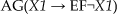
to express deadlock freedom. The property works by stating that, for all states (AG) where some condition X1 holds, there exists an execution path where a state will eventually be reached (EF) in which the condition no longer holds (i.e., the state of X1 can always change).
6. Tool support
As already discussed, expressing properties in a formal logic can be a complex task. While the patterns described above can be a useful tool in dealing with this complexity, the manual process of selecting and instantiating a pattern is error prone and such errors can be hard to detect. This is particularly the case when complex formulae are at stake.
In order to address this, a tool to help pattern instantiation has been developed. The tool (Properties Editor – see Figure 3) is based on the notion of property patterns described above. A list of property patterns and help for instantiating those patterns, is provided.
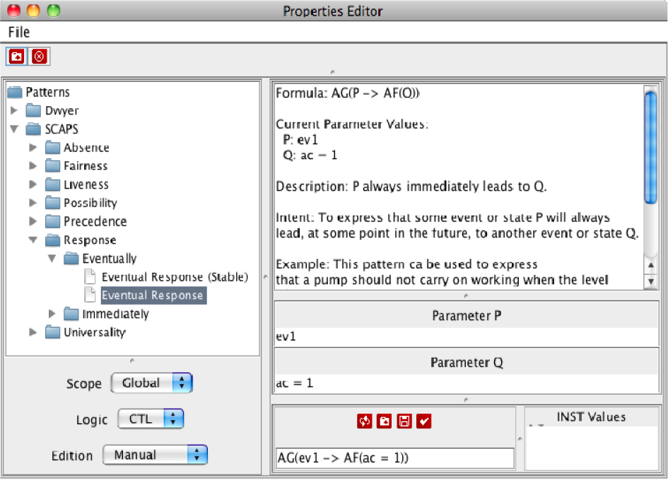
The Patterns tool
The patterns include all the information in the original patterns, such as the intention and known uses. This allows the user to browse the patterns in order to select the most adequate one for the property of interest. Additionally the tool allows for the definition of the scope for the property and of the logic to be used (currently CTL and LTL are supported).
Instantiation of patterns to produce a property specification is done by indicating values for the patterns parameters. In Figure 3 the user has selected the Eventual Response pattern (see the patterns tree on the left) and provided the value “ev1” for parameter P and the value “ac=1” for parameter Q (see bottom half of right side). According to the template and since the CTL logic and a Global scope have been selected (see pull down menus on the bottom left), the tool is generating the property (see bottom right):

which, as required, states that “ev1” will always lead to “ac=1”.
As illustrated in the figure (see patterns' tree), the tool supports different collections of patterns. In the current case, both the patterns in [9] (Dwyer) and the patterns introduced above (SCAPS) are being made available (although only the branch corresponding to this last collection has been expanded). Explaining the implementation of the tool is out of the scope of the current paper, but in short, a DTD (Document Type Definition) for the description of patterns has been developed and support for reading pattern collections expressed in XML, in accordance to that DTD, integrated into the tool. This will then be enough to create XML files for each new pattern collection and the tool will load the appropriate patterns on request.
Additionally, the tool provides a mechanism to generate more than one property from the same pattern. This is achieved through the INST meta-variable.
7. Applying the pattern collection – an example
In this section we use an example, taken from [30], to illustrate how the pattern collection can be useful in the analysis of Discrete Event Systems.
7.1 The example system
The system chosen for this case study lies in the well-known category of “pick-and-place” systems (see Figure 4).
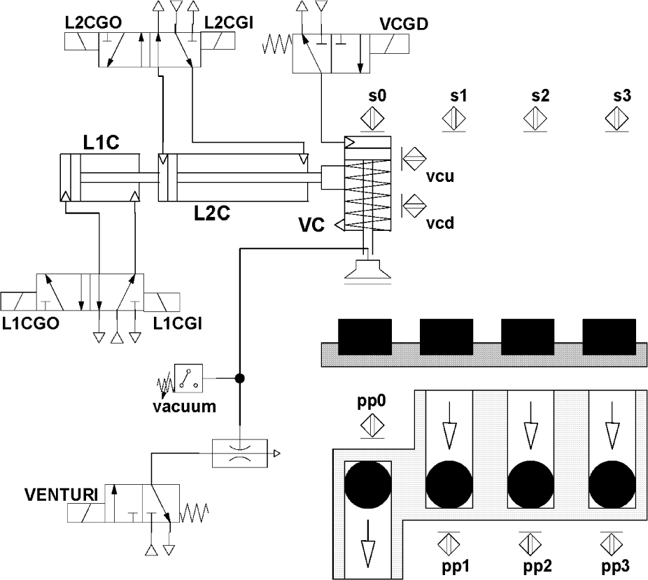
Plant of the “pick-and-place” system
This system is representative, from the point of the class of electropneumatic systems, in terms of physical analysis because it is characterized by having monostable and bistable directional valves, single-acting and double-acting cylinders, position sensors (limit switches) of the cylinders, which behaviour depends from one only cylinder (sensors associated to the vertical cylinder) and position sensors that depend from position than more than one cylinder (sensors associated to the position of the horizontal cylinders). Also the fact that one part can appear at any moment at one of the three feeding conveyers is an added value from the point of view of the diversity that can be found in this system. This is the reason why patterns developed and tested using this system are stronger and representative for systems of the same kind.
The function of this system is to take parts, fed by gravity into three feed chutes, for placement in a single unloading chute. Sensors pp1, pp2 and pp3 indicate the presence of a part in one of the feed chutes, while sensor pp0 signals the presence of a part in the unloading chute.
The device that enables the picking and placing of a part is composed of a group of three pneumatic cylinders plus a vacuum suction cup system. The vertical cylinder (VC) places the suction cup in contact with a part. Longitudinal cylinders L1C and L2C are arranged in series to allow positioning of the vertical cylinder VC in front of the four chutes (L2C stroke is twice as long as than L1C stroke). The four positions reached are thereby detected by position sensors s0, s1, s2 and s3. The depression in the suction cup is obtained by virtue of a venturi device and detected by a vacuum sensor.
The vertical cylinder is controlled by a monostable electro-valve (order VCGD – Vertical Cylinder Go Down) and its positions of end of stroke are detected by vcu (vertical cylinder up) and vcd (vertical cylinder down) sensors.
The horizontal cylinders L1C and L2C are controlled by bistable electro-valves and the control orders of the corresponding electro-valve are L1CGO (L1C Go Out) and L1CGI (L1C Go In). By analogy, orders L2CGO and L2CGI are the orders sent from the controller to the electro-valve of cylinder L2C for, respectively, the moving forward and moving back of the cylinder L2C piston rod.
For the picking-up of the parts, the order VENTURI is sent from the controller to the electro-valve associated and the aspiration is detected by the sensor vacuum.
This system was formally modelled to allow for formal verification. Describing the model is out of the scope of this paper (see [30] for a description). Here we are interested in expressing the properties. For the discussion that follows it is enough to know the meaning of the variables described below.
The following variables are used to represent plant model states:
V_P2: VC is in the deployment movement V_P5: L1C is in the retracted position V_P6: L1C is in the deployment movement V_P7: L1C is in the deployed position V_P8: L1C is in the retraction movement V_P9: L2C is in the retracted position V_P10: L2C is in the deployment movement V_P11: L2C is in the deployed position V_P12: L2C is in the retraction movement
Concerning controller model states, a family of variables (Xi) is used to represent the internal state of the controller during the evolution of the system.
7.2 Desired System Behaviour
Informally the desired system behaviour can be described by the following nine properties:
PR_1.i: The controller never commands horizontal cylinder i in two directions at the same time PR_2: If the controller commands the vertical cylinder to go down, then it must not command any movement to the horizontal cylinders PR_3: The controller commands horizontal cylinders only while sensor vcu is on PR_4: After the part is picked up, in the “pick-up position”, it must not be dropped down until the suction cup reaches the “place position” PR_5: The horizontal cylinders move only while sensor vcu is on PR_6.i: The controller model must not have deadlock PR_7.i: When a part is detected by sensor ppi, then in the future, the corresponding horizontal cylinder(s) will be deployed PR_8.i: When a part is detected by sensor ppi, then in the future, it will be picked PR_9: While the vertical cylinder is moving down, all the other cylinders stay in deployed or retracted position.
7.3 Property Formalization
Machado [30] used CTL to express all but one property. In the case of property PR_4 an observer automata was used, due to the complexity of the behaviour that was being expressed. In all cases, only stable states were considered for verification (represented by variable stable).
In the following we will show how the pattern collection can ease the process of property formalization. We will do this by selecting appropriate patterns for each property and instantiating its parameters with appropriate expressions. The generated formulae are presented in Table 1 below.
Results from applying the patterns

Property PR_1.i can be seen as wanting to guarantee that the system will never reach undesirable states. Looking at the pattern collection, this can be expressed using the Absence pattern (Section 5.3) and the Global scope. We need only define what the undesirable states are for each cylinder and instantiate P in the parameter with them. For L1C P becomes L1CGO ∧ L1CGI. For L2C P becomes L2CGO ∧ L2CGI. By applying the pattern we get the first two formulae in Table 1.
Four of the eight remaining properties correspond to conditions we want to always hold. This is true of properties PR_2, PR_3, PR_5 and PR_9. In this case we need only define what the condition is and use the Universality pattern (Section 5.4) with the Global scope. For PR_2 P becomes VCGD → ¬(L1CGI ∨ L1CGO ∨ L2CGI ∨ L2CGO) (i.e., movement in the vertical cylinder means no movement in the horizontal ones). By applying the pattern we get the third formula in the table. The same is done for the other properties.
Property PR_4 refers to a property that must always be true between two specific instants. We want to guarantee that the piece never drops down between the pick-up and place positions. Again, this can be expressed using the Universality pattern, but now with the “After…Until…” scope. P becomes vacuum (the piece never drops down), St (the pick-up position) is replaced by (s1∨s2∨s3)∧vcd and Sp (the place position) by s0 ∧ vcd. Instantiating the pattern we get the fifth formula in the table.
Notice that we used the stable version of the “After… Until…” scope. Notice also that, for simplicity, in the table the weak until operator is used. The tool does not use weak operators since these are typically not supported by model checkers. Hence, the generated formula becomes:
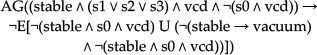
In property PR_6 we want to ensure that the system state can always evolve. This can be defined using the Liveness pattern (Section 5.7) for each of the Xi internal state variables. Defining P as X1 and Q as ¬X1, we get the seventh formula in the table. The same process is applied to each variable (X1 to X38). In fact, the tool supports the simultaneous generation of the 38 needed formulae in one step (for simplicity we only present the first and last ones). This is achieved by creating a list of variables in the INST values field (bottom right corner of Figure 3) and automatically applying the pattern to the list. Note that, following [30], in this case we chose not to consider stable states only.
Properties PR_7.i and P_8.i are similar. Both are instances of the Eventual Response pattern (Section 5.5). For sensor pp1 we replace P with pp1 and Q with V_P6 (the corresponding cylinder) to get the ninth property in the table, which corresponds to PR_7.1. For PR_8.1 we replace P with pp1 and Q with s1 ∧ vcd ∧ vacuum (i.e., the vertical cylinder is down at the right position and there is vacuum in the suction cup). For the remaining cases the process is the same.
Table 1 summarizes all the properties that were generated. It must be stressed that all the properties, no matter how complex, were generated automatically without the need to write any CTL code. As noted above, in [30] the option was available not to try writing a CTL formula for PR_4 and an observer automata was used instead. Using patterns, generating this complex property was no more difficult than generating the property for the simpler cases. On the contrary, using an observer automata meant some additional modelling work had to be carried out and also that the property formalization was done differently from the other ones.
For illustration purposes, the automaton used in [30] is presented in Figure 5. The automaton has three states that model the following behaviour:
PR1: models the absence of a sucked part PR2: models the presence of a sucked part (not yet dropped off) PR3: models an undesired behaviour: the dropping off of the part between the pick-up and place positions.

Sequential modelling of property PR_4
The transitions between the three states perform synchronization with the model being verified and define the conditions under which each transition is valid. In order to prove PR_4, the following CTL formula was proved of the joint behaviour of the model and the automata: AG¬(PR3 ∧ stable)
Comparing this with the three small propositional formulas that were needed to instantiate the Universality pattern, it can be seen that using the pattern was much simpler. This is especially the case since the property patterns tool supports the exploration of the patterns to identify the best candidate in each situation.
8. Conclusions
Model checking is becoming an established technique for the formal verification of Discrete Event System (DES) automation. A finite state system can be represented by a labelled state transition graph and the properties of the system (expressed as formulae in temporal logic) checked by traversing the graph of the transition system, verifying that it satisfies the formula representing the property.
As verification tools gain popularity, the problem arises of making them more accessible to engineers. Three main problems can be identified: writing the models, writing properties for analysis and analysing the results. Typically the literature addresses the first problem, paying little attention to the remaining two. However, if verification tools are to be successful outside the limited group of experts in the formal approach each tool supports, support for expressing properties and understanding results is also needed.
In this paper we have looked at the issue of supporting the expression of property specifications. A study was carried out of the properties present in the automated production systems analysis literature and a collection of patterns has been put forward as an aid to expressing relevant properties of a system's behaviour. Together with its tool support, this pattern collection enables the expression of complex properties using basic knowledge of propositional logic only.
The applicability of the pattern collection was demonstrated with an example. Comparing our results with those of [30], we can see that we obtained equivalent CTL formulae for all properties (except PR_4). However, we do so without the need to resort to temporal logic expertise. The only requirements were an understanding of the problem domain and basic propositional logic knowledge. The temporal logic aspects were captured by the patterns. In the special case of PR_4, we were able to generate a temporal formula (again, using propositional logic to instantiate the pattern) while originally there was a need to resort to an observer automaton.
The tool is being made available at: http://www.di.uminho.pt/~jfc/PatternsTool/