
Abstract
Abstract An automatic design platform capable of automatic structural analysis, structural synthesis and the application of parallel mechanisms will be a great aid in the conceptual design of mechanisms, though up to now such a platform has only existed as an idea. The work in this paper constitutes part of such a platform. Based on the screw theory and a new structural representation method proposed here which builds a one-to-one correspondence between the strings of representative characters and the kinematic structures of symmetrical parallel mechanisms (SPMs), this paper develops a fully-automatic approach for mobility (degree-of-freedom) analysis, and further establishes an automatic digital-analysis platform for SPMs. With this platform, users simply have to enter the strings of representative characters, and the kinematic structures of the SPMs will be generated and displayed automatically, and the mobility and its properties will also be analysed and displayed automatically. Typical examples are provided to show the effectiveness of the approach.
Keywords
1. Introduction
Symmetrical parallel mechanisms (SPMs) not only have the advantage of high rigidity, high strength, high load carrying capacity, low inertia, and good dynamic performance, but also possess the property of isotropy making them adaptable to various different tasks [1–2]. In the past decades, many scholars [3–8] have conducted research into SPMs using various approaches. With the development of computer technology, the methodology of digital research into mechanisms is a new area of research, which concerns how computers can carry out analyses, thus saving on human labour, and improving automation and intelligence in mechanical conceptual design [9]. Freudenstein [10] was the first to attempt the computer-based automatic sketching of mechanisms for conceptual design. Later, Mruthyunjaya [11], Yan [12] and Wang [13] promoted the development of a methodology for the creative synthesis of mechanisms. However, there is still no automatic digital-analysis platform for mobility analysis and kinematic structure sketching of SPMs.
The structural representation of SPMs is one of the most significant issues in this field of study. It should include all the topological information of SPMs so that these can be identified by the computer. The traditional structural representation of an SPM consists of the number of limbs and the types of kinematic pairs in a limb[14]. For example, 3-UPU denotes an SPM which possesses three limbs, each of which contains a universal pair, a prismatic pair and a universal pair from the base to the moving platform in turn. While the simplicity of this representation make it visually pleasing, it however results in the key information of the geometrical relationships between joint axes being left out, which affect such important kinematic characteristics of SPMs as mobility and its properties. Geometrical relationships between joint axes were first proposed by Dizioglu [15] in Germany. To describe these relationships, Huang and Li [2,16] proposed a representation using superscript and subscript symbols. Kong and Gosselin [17–19] proposed a concept, “leg-group”, and a form of representation using some special notations. No matter what the representation might be, if it is to be used in the automation of the conceptual design of SPMs, one property of the representation must be a one-to-one correspondence between the strings of representative characters and the kinematic structures of the SPMs. However, this is the very problem which has not yet been solved and is also one important reason why an automatic digital-analysis platform for mobility analysis and kinematic structure sketching of SPMs has not yet been developed.
The mobility of mechanisms is the first aspect to be considered in the study of kinematics and the dynamics of mechanisms [20]. Besides, what needs to be known is not only the mobility itself, but also the mobility's properties concerning the numbers of rotations and translations. A great many methods for mobility analysis have been put forward [22–26], whereby the work would be done manually. However, a digital-platform for automatic analysis has not been developed, the lack of which hampers the automation of the conceptual stage of mechanical design. Methods [2, 18, 21, 22, 26] based on the screw theory, the calculation of which mainly involves matrix operations, have the potential advantages of automatic analysis. However, there is no evidence as yet that the process of obtaining screws can be carried out by computers using the existing methods, which means automatic mobility analysis cannot be carried out.
In this paper, a new method of structural representation and a method for the programmable mobility analysis of SPMs are proposed. Based on these methods, a conceptual digital-analysis platform was created, using which the sketching of the kinematic structures of SPMs and the analysis of mobility and its properties can all be carried out automatically. Several examples are given to verify the effectiveness of the method.
2. Structural representation of SPMs
An SPM consists of a base (fixed platform), a moving platform and several identical structural limbs connecting the two platforms with geometrical symmetry. The traditional representation of SPMs is simple, but it does not reveal the basic geometrical relationships between joint axes which affect the kinematic characteristics of SPMs, such as mobility and its properties. Here, a new structural representation of SPMs is proposed, which consists of a structural representation of the platforms (the base and the moving platform) and a structural representation of the limbs.
2.1 Structural representation of the platforms
In an SPM, the two end joints of a limb are connected with the two platforms. The relationships between the axis of an end joint and a platform (line-plane relationships) can be classified into three basic types: parallel, vertically intersecting and generally intersecting, denoted by the characters ‘/’, ‘+’ and ‘∧’, respectively. A platform is usually connected to two or more limbs. The relationships between the axes of the end joints which are connected to a platform (relationships between rotational symmetrical lines) can also be classified into three types: parallel to one another, intersecting at one point, and forming a polygon, denoted by the characters ‘/’, ‘∧’, and ‘#’, respectively.
Based on the characteristics of the SPMs, the structural representation of a platform can take one of the following five types.
The axes of the end joints which are connected with the platform intersect vertically (+) with the platform. In this case, all these axes are also parallel (/). So the structural representation of the platform is ‘+/’, as shown in Fig.1(a). The axes of the end joints connected with the platform generally intersect (∧) with the platform. In this case, these axes also intersect at one point (∧) in space. So the structural representation of the platform is ‘∧∧’, as shown in Fig.1(b). If the axes of the end joints which are connected to the platform are parallel (/) to the platform, it takes one of the following types (3)–(5). The axes are also parallel (/). The structural representation of the platform is ‘//’, as shown in Fig.1(c). The axes intersect (∧). The structural representation of the platform is ‘/∧’, as shown in Fig.1(d). The axes form a polygon (#). The structural representation of the platform is ‘/#’, as shown in Fig.1(e).

Types of geometrical relationships on the platforms
So for SPMs, there are five types of platforms, as shown in Table 1.
Five types of platforms and their representation characters

2.2 Structural representation of the limbs
Each limb in an SPM is a serial kinematic chain the structural representation of which consists of the types of joints and the geometrical relationships between the joint axes in the limb.
The kinematic pairs of SPMs are denoted by symbols: P for a prismatic pair, R for a revolute pair, C for a cylindrical pair, U for a universal pair, H for a helical pair and S for a spherical pair. As we know, a U pair can be regarded as a combination of two R pairs with intersecting and orthogonal axes, an S pair can be regarded as a combination of three R pairs with concurrent axes, and a C pair can be regarded as a combination of one R pair and one P pair with the same joint axis.
In a limb, the geometrical relationships between the joint axes fall into five types: parallel (‘/’), vertical and intersecting (‘+’), vertical but not intersecting (‘!’), intersecting (‘∧’), and skew lines (‘&’). If three joint axes in a limb are intersecting at one point, they are denoted as ‘*’. The geometrical relationships between joint axes in a limb and the characters representing them are listed in Table 2.
Representation characters between joint axes in a limb

One of the limbs in an SPM can be chosen as the reference limb (RL), and we only need to know the representation of the RL in order to know those of the other limbs with the same structures. In the RL, the kinematic pairs are labelled in turn with the numbers 1˜j (j denotes the number of kinematic pairs in the RL) from the base to the moving platform. Pair 1 is connected to the base and defined as the basic pair (BP).
A reference pair (RP) is needed to represent a joint axis in space. Usually, joint (i-1) is chosen as the reference pair for joint i. However, if one of the joints 1˜(i-2) is parallel to, vertical to or intersects the axis of joint i, this joint instead of joint (i-1) is chosen as the reference pair. There is no need to choose a reference pair for the basic pair since its joint axis has been determined by the structural representation of the fixed platform. The representation of a pair i consists of the type of the pair, the label of the RP (omitted if joint (i-1) is the reference pair) and the geometrical relationship between the axes of the pair and its RP. In addition, if two or three joint axes in the RL intersect at a given point and the corresponding joint axes in the other limbs also intersect at the same point, character ‘|’ is added at the end to represent the case.
For example, the limb in Fig.2 has five R pairs, labelled with the numbers 1˜5. The axes of pairs 2 and 3 are parallel to that of pair 1, the axis of pair 4 intersects the axis of pair 3, and the axis of pair 5 is parallel to the axis of pair 4. Consequently, the RP of pairs 2 and 3 is pair 1, the RP of pair 4 is pair 3 and the RP of pair 5 is pair 4. Pair 1 is the BP and it is represented with ‘R’. The representations of pairs 2˜5 are ‘R/’, ‘R1/’, ‘R∧’ and ‘R/’, respectively. Therefore, the structural representation of the limb is ‘RR/R1/R∧R/’.
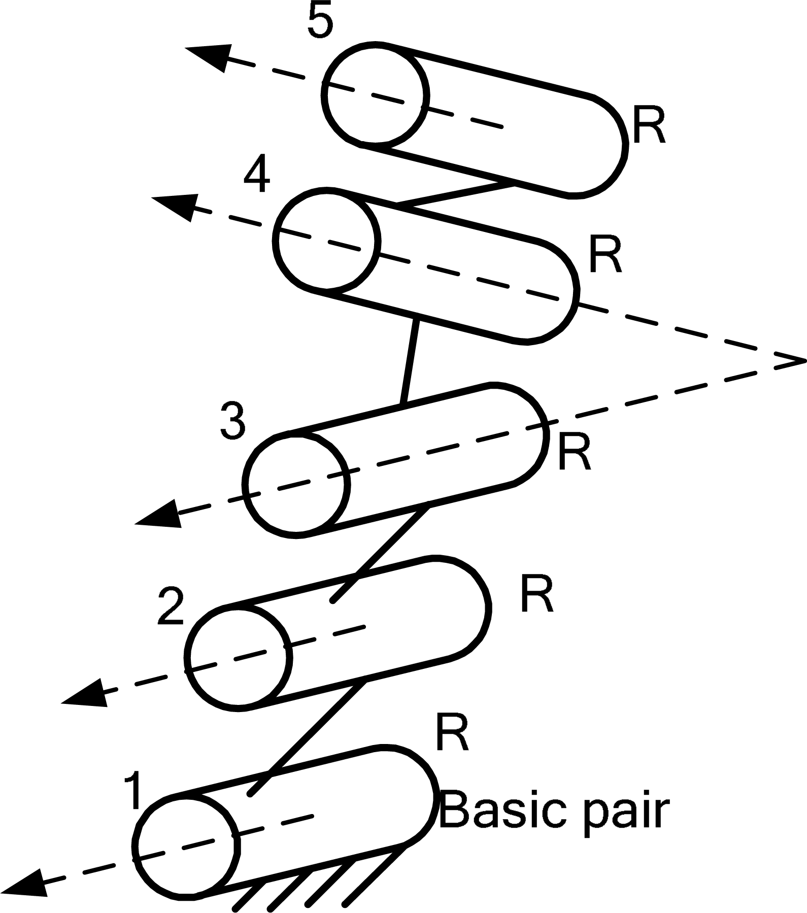
A ‘RR/R1/R∧R/’ limb
In Fig.3, the limb has four R pairs and one P pair. The axis of pair 2 is perpendicular and intersects with pairs 1 and 3, the axes of pairs 3 and 4 are skew lines, the axis of pair 5 intersects the axis of pair 4, the axis of pair 3 is parallel to the axis of pair 1. So the representations of pairs 1˜5 are ‘R’, ‘P+’, ‘R1/’, ‘R&’ and ‘R∧’, respectively. Therefore, the structural representation of the limb is ‘RP+R1/R&R∧’.

A ‘RP+R1/R&R∧’ limb
2.3 Structural representation of SPMs
The string of representative characters is used to represent the structure of a complete SPM. Its form is “representation of the base - representation of limbs - representation of the moving platform”.
In Fig.4(a), the SPM has three limbs. The three joint axes connected to the base are parallel to the base, and they form a polygon. So, the structural representation of the base is ‘3/#’. The structural representation of the moving platform is ‘3/#’. The reference limb consists of an R pair, a P pair and a C pair. The axis of the P pair vertically intersects with that of the R pair, and the axis of the C pair is parallel to that of the R pair. So the representation of the reference limb is ‘RP+C1/’. Therefore, the string of representative characters of the SPM is ‘3/#-RP+C1/-3/#’. Similarly, the strings of representative characters of the SPMs shown in Fig.4(b) and 4(c) are ‘3+/-RR/R+R∧R*|-3∧∧’ and ‘3/#-RP+R1/R!R∧|-3∧∧’.

Several SPMs
The string of representative characters of an SPM contains the geometrical relationships between the joint axes, so it is useful in the automatic sketching of kinematic structures and the automatic analysis of the mobility and its properties of the SPM.
3 Method for the automatic analysis of the mobility and its properties
In the screw theory[14, 24], a unit screw

where
where “o” denotes the reciprocal product and

where

where
Although the screw theory is good for mobility analysis, it cannot be directly applied to automatic mobility analysis [27]. Here, based on the string of representative characters and the screw theory, a fully-automatic method for the analysis of the mobility and its properties is presented.
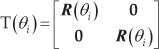
The establishment of a coordinate system is the basis for obtaining screws. For a given SPM, any one of its limbs can be chosen as the RL. In general, we label the limbs with the numbers 1, 2, 3˜k, and limb 1 is chosen as the RL. The coordinate system O-XYZ is determined by the following rules: if two or more joint axes intersect at one point in the RL and the corresponding joint axes in all the other limbs also intersect at the same point, the intersecting point is used as the origin. The X-axis is parallel to the line connecting the centre point of the base and the centre point of the BP of the RL. The Z-axis is perpendicular to the base plane and goes upward. The Y-axis is obtained using the right-hand rule. Here, this is called mode 1. Otherwise, if there is no common point of intersection, the coordinate origin is the centre point of the base plane. The X-axis is the line connecting the origin coordinate with the centre point of the BP of the RL. The Z-axis is also perpendicular to the base plane and goes upward. The Y-axis is obtained using the right-hand rule. Here, this is called mode 2.
If a pair is a P joint, only the joint axis needs to be known and its twist screw is expressed as (0;
Twist screws of the BP

The twist screws of the other pairs in the RL can be obtained from the geometrical relationships and the twist screws of the RPs. The axis direction of a RP may be parallel to the X-axis, namely,
Twist screws of other pairs for the RP (S1= (0 cos(b1) cos(c1)), r1= (l1 m1 n1))

Twist screws of other pairs for the RP (S1= (1 0 0), r1= (l1 m1 n1))
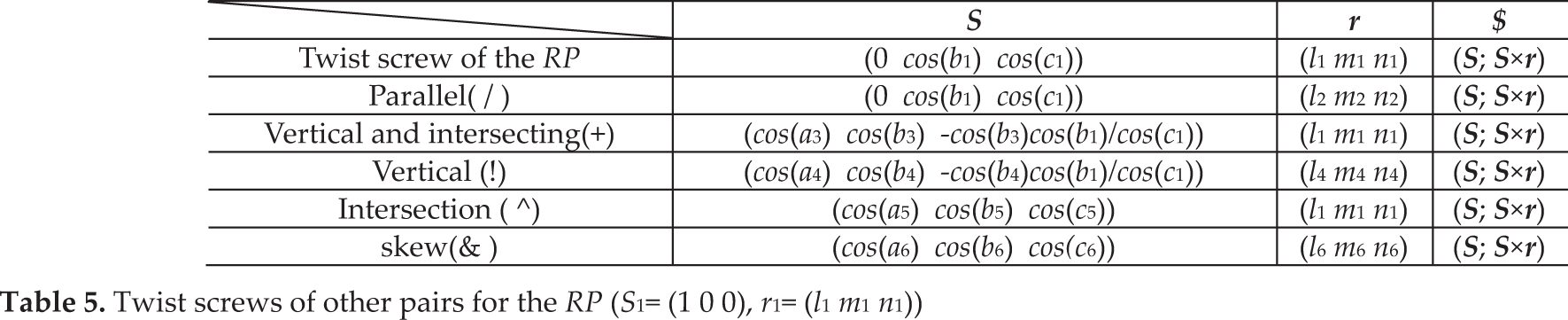
Twist screws of other pairs for the RP (S1= (cos(a1) cos(b1) cos(c1)), r1= (l1 m1 n1))

Taking the string of representative characters ‘3/#-RP+C1/-3/#’ for example, the origin of the coordinate system O-XYZ is the centre point of the base plane. Thus, the twist screw of the BP is (0 1 0; (l m 0)×(0 1 0)), in which
With this method, the twist screw system,

where j denotes the number of twist screws.
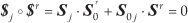
According to the reciprocal product

where, h=6-j, h is the number of the wrench screws of the RL.
The wrench screw system,

The limb number of an SPM is denoted as k, thus,

Then
where

Consequently, the wrench screw systems,


Mobility properties can be analysed by solving the reciprocal screw (denoted by

Two SPMs
Step 1: The central point of the base is chosen as the origin of the coordinate system according to the rules (mode 2).
Step 2: The representation of the base is ‘4/#’ and the twist screw of the BP can be expressed as

According to the reciprocal product relationship, the wrench screw system is
Step 3: The other three wrench screw systems

Step 4: The maximum linear independent group,

The rank, D, of the wrench screw set which consists of the wrench screw systems,

Step 5: The mobility of the moving platform is F=6-D=1. The twist screw of the moving platform is
Step 1: Some corresponding joint axes in the limbs intersect at one point. This point is used as the origin of the coordinate system (mode 1). The X-axis is parallel to the line connecting the origin coordinate with the central point of the BP of the RL. The Z-axis is perpendicular to the base plane and goes upward.
Step 2: The representation of the base is ‘3/#’, so,
The twist screw system

So, the wrench screw system of the RL is
Step 3: The other two wrench screw systems,

Step 4: The maximum linear independent group,

The rank, D, of the wrench screw set which consists of the wrench screw systems

Step 5: The mobility of the moving platform is F=6-D=4. The twist screw of the moving platform is
which denotes that the moving platform has three rotational freedoms around the X-axis, Y-axis and Z-axis, respectively and a translation freedom along the Z-axis.
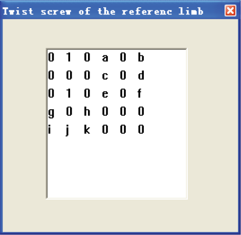
4. Digital-analysis platform
Following the approach above, a digital-analysis platform for SPMs was developed successfully for the first time. Using this platform the kinematic structures of SPMs can be sketched and the mobility of SPMs can be analysed automatically based on the input of the structure in the form of a string of representative characters. The flow chart of the digital-analysis platform is shown in Fig.6. For the sake of convenience, when sketching the kinematic structures of mechanisms, some symbols are used to represent different pairs:  for the R pair,
  for the P pair,
  for the H pair,
  for the U pair,
  for the C pair, and
  for the S pair, as shown in Table 6.

The flow chart of the digital-analysis platform
Kinematic pairs and their corresponding symbols

5. Several typical examples
In the twist screws of the limbs or the moving platform, if one component of

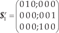
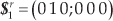
The analysis of the ‘3/#-RP+C1/-3/#’ SPM based on the developed platform

Twist screw of the RL

Twist screw of the moving platform

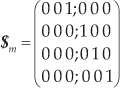
The analysis of the ‘4/#-RR/R-4/#’ SPM based on the developed platform

Twist screw of the RL

Twist screw of the moving platform

The analysis of the ‘3/#-RP+R1/R!R∧|-3∧∧’ SPM based on the developed platform
Twist screw of the RL

Twist screw of the moving platform
6. Conclusions
In this paper, a new structural representation for SPMs is presented, with which strings of representative characters have a one-to-one correspondence with the structures of SPMs. The string of representative characters is intuitive and vivid enough for users to write and read easily. It is also identifiable by computers.
Based on the string of representative characters and the screw theory, a new method for analysing the mobility of SPMs is proposed, which is also legible for computers.
A conceptual digital-analysis platform was created for the first time, using which the kinematic structure of SPMs can be sketched and their mobility can be analysed automatically, based on a given string of representative characters. Several typical examples are given at the end of the paper, illustrating the effectiveness of the method. In brief, the digital-analysis platform developed here is effective and efficient in analysing the mobility of SPMs. It achieves the automation and intelligence of mobility analysis and structure sketching, which will lay a good foundation for the automation of mechanical conceptual design.
7. Acknowledgements
The authors are grateful to the project (No.51275437, 50905155) supported by NSFC, the Hebei Nature Science Foundation (No.E2012203154), the 2012 open project of State Key Laboratory of Mechanical Transmission (No. SKLMT-KFKT-201208) and the Programe of Excellent Young Scientists of the Higher colleges of Hebei province (No.CPRC017).